Page is loading ...

860 SERIES RELAY MODULE
Installation Guide
DESCRIPTION
MODEL
860
4 3 2 1
RELAY
COILS
1
234
+12
RELAY 4 RELAY 3 RELAY 2 RELAY 1
NO C NC NO C NC NO C NC NO C NC
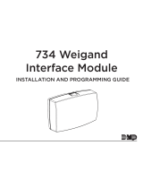
Dry relay contacts on
the860Module are programmable
and controlled from panel
annunciator outputs. The module
includes one FormC (SPDT)
relay rated for1Amp at30VDC.
The860Module also provides
three additional sockets for
Model305Plug-In Output
Relays(12VDC).
Relays can be used for electrical
isolation between systems or for
switching5, 12, or24Volts to
control various functions within a
building or around its perimeter.
Compatibility
• XT30/XT50Series panels
• XR150/XR550Series panels
What is Included?
• One860Relay Module
• OneModel 330 Dual-Ended
4-Wire Harness
• Hardware Pack
1MOUNT THE MODULE
Themodule can be mounted in a DMP enclosure using the
standard3-hole mounting pattern. Refer to Figure 2 as needed
during installation.
1. Hold the plastic standos against the inside of the enclosure
side wall.
2. Insert the included Phillips head screws from the outside of
the enclosure into the standos. Tighten the screws.
3. Carefully snap the module onto the standos.
WIRE THE MODULE
2Caution: Disconnect all power from the panel before wiring
the module. Failure to do so may result in equipment damage
or personal injury.
Refer to Figure 3 as needed during wiring. For power
connections, use 22 AWG or larger wire.
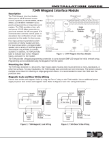
1. Connect the included4-wire harness from the module
RELAY COILS header to the panel OUTPUTS header.
2. Connect a wire from the860Power Terminal (+12) to panel
Terminal7 (RED) or505-12 (DC+).
3. To install additional Model305relays, line up the relay with
the PCB pins and gently press the relay into the socket.
4. Connect relay terminals NO, C, and NC to devices as
needed for each installed relay. Refer to Applications for
more information.
Figure 1: 860 MODULE
Figure 2: Stando and Module
Installation
BACK
1
2
3
MODEL
860
PANEL
4 3 2 1
RELAY
COILS
To Panel
OUTPUTS
Header
1
234
+12
RELAY 4 RELAY 3
Model 305 Relay Sockets
RELAY 2 RELAY 1
NO C NC NO C NC NO C NC NO C NC
RED
RED
Normally Open
Common
Normally Closed
BLACK
To 860
RED
BLACK
To Panel Terminal 7
(RED) or 505-12 (DC+)
To Device
Relay Contact Rating:
1 Amp @ 30 VDC,
resistive.
Figure 3: Wiring Connections

Designed, engineered, and
manufactured in Springfield, MO
using U.S. and global components.
LT-0484 1.04 20271
860 SERIES RELAY
MODULE
Specifications
Operating Current 12VDC
Operating Current
One Relay 34mA
Two Relays 69mA
Three Relays 104mA
Four Relays 138mA
Weight 3.2 oz (0.09 kg)
Dimensions 4.25” W x 2.50” H
10.8 cm W X 6.4 cm H
Ordering Information
860 Relay Output Module (one relay included)
860-4 Relay Output Module (four relays included)
Accessories
Model 305 Plug-in Output Relay (12 VDC Form C SPDT)
Compatibility
XT30/XT50 Series Panels
XR150/XR550 Series Panels
Certifications
California State Fire Marshal (CSFM)
New York City (FDNY)
Underwriters Laboratory (UL) Listed
ANSI/UL 365 Police Station Alarm Units
ANSI/UL 609 Local Burglary Alarm Units and
Systems
ANSI/UL 864 Fire-Protective Signaling Systems
ANSI/UL 985 Household Fire Warning System Unit
ANSI/UL 1076 Proprietary Burglary Alarm Units and
Systems
ANSI/UL 1610 Central Station Burglary Alarm Units
ULC Subject-
C1023 Household Burglar
ULC/ORD-C1076 Proprietary Burglar
ULC S304 Central Station Burglar
ULC S545 Household Fire
MODEL
860
4 3 2 1
RELAY
COILS
1
234
+12
RELAY 4 RELAY 3 RELAY 2 RELAY 1
NO C NC NO C NC NO C NC NO C NC
INTRUSION • FIRE • ACCESS • NETWORKS
2500 North Partnership Boulevard
Springfield, Missouri 65803-8877
800.641.4282 | DMP.com
© 2021
ADDITIONAL INFORMATION
Wiring Specifications
DMP recommends using 18 or 22 AWG for all LX-Bus and Keypad Bus connections. The maximum wire distance between
any module and the DMP Keypad Bus or LX-Bus circuit is 1,000 feet. To increase the wiring distance, install an auxiliary
power supply, such as a DMP Model 505-12. Maximum voltage drop between a panel or auxiliary power supply and any
device is 2.0 VDC. If the voltage at any device is less than the required level, add an auxiliary power supply at the end of
the circuit.
To maintain auxiliary power integrity when using 22-gauge wire on Keypad Bus circuits, do not exceed 500 feet. When
using 18-gauge wire, do not exceed 1,000 feet. Maximum distance for any bus circuit is 2,500 feet regardless of wire
gauge. Each 2,500 foot bus circuit supports a maximum of 40 LX-Bus devices.
For additional information refer to the LX-Bus/Keypad Bus Wiring Application Note (LT-2031) and the 710 Bus Splitter/
Repeater Module Installation Guide (LT-0310).
Applications
The panel annunciator outputs are switched ground and switch each of the four Model860relay coil voltages to ground.
These outputs can be programmed to respond to any of the conditions listed below:
• Zone condition • Fire alarm or fire trouble • Ground start activation
• Manually from the keypad • Ambush alarm • Burglary alarm
• Communication failure • Exit and entry timers • Schedules
• Armed area annunciation • System ready • Other system conditions
See the appropriate panel programming guide for information about voltage limitations and programming annunciator
outputs.
Compliance Listing Specifications
ULC Commercial Burglary (XR150/XR550Series Panels)
If installed in another enclosure, place the relay module with at least one zone expander in a listed enclosure. Connect a
DMP Model307Clip-on Tamper Switch to the enclosure and program it as asupervisory zone in Zone Information (SV).
For more information, refer to the appropriate panel installation and programming guides.
/