Page is loading ...

The Model A220FP Fragrance Injector Pump is to be used with the AK and 3K steamers when the K200i Freedom
Control is not installed. The pump should be mounted in an easily accessible area, not more than 4' above the essence
container and not more than 4' below the saddle valve. The on/off switch located on the side of the fragrance injector
pump must be turned on and remain in the on position.
4211-189 08-09-11
DIAGRAM 1
WARNINGS
The use of fragrance oils may introduce excessive concentration of oil into the steam room, resulting in a health
hazard.
Leave the room immediately if you have any adverse or allergic reactions, including difficulty breathing or eye, nasal,
throat or skin irritation, and seek immediate medical attention.
Vapors may cause drowsiness and dizziness. Keep out of the reach of children. In case of contact with eyes, rinse
immediately with plenty of water and seek medical advice. If swallowed, rinse mouth with water (only if person is
conscious) and seek medical advice immediately.
Essential oils may be highly flammable! Keep away from sources of ignition. No smoking! Keep container tightly closed
and in a well ventilated place.
Not for use in acrylic or fiberglass rooms.
The pump has been factory set to deliver a suitable amount of aromatic oil into a typical sized steam room. Use
caution when increasing the speed on the pump as this may introduce excessive concentration of oil into the steam
room, resulting in a health hazard.
A220FP Fragrance Injector Pump
Installation and Operating Instructions
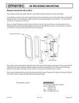
AK Steam
Generator
Fragrance
Injector Pump
Saddle Valve (supplied)
Mount on top of Steam Line
Essence Container
(supplied)
Thermal Switch
(supplied)
Mount on top
of Steam Line
120VAC - 24VAC
Power Adapter
Fragrance
Controlller
Clear
Tubing
(supplied)
On/Off
Switch
3' Min.
Installation Overview

4211-189 08-09-11
A220FP Fragrance Injector Pump
Installation and Operating Instructions
page 2
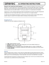
DIAGRAM 3
DIAGRAM 2
Piercing Arm
Brass Nut
Brass
Sleeve
Plastic
Compression
Fitting
General Installation
Determine locations suitable for mounting the Fragrance system's components:
• The On/Off switch should be mounted where it is convenient to the user. It is used to start or stop the fragrance controller.
The switch may be mounted inside or outside the steam room. A 25' cable is provided to connect the switch to the
Controller.
• The essence bottle and pump should be located where they are protected from freezing, easily accessible for checking the
level of and refilling the essential oil, and where the bottle will be no more than 4' below the pump with the pump mounted
on a vertical surface. Do not install near flammable or corrosive materials or chemicals, in areas having high concentrations
of chlorine or near open flames. Thirteen feet of clear tubing is provided to connect the pump to the essence bottle and to
the saddle valve. The pump's 9' power cord will connect to the controller.
• Locate the saddle valve and the thermal switch near each other on the top of the steam outlet pipe, at least 3' from the steam
generator (as close to the steam room as possible for best results) and with the saddle valve no more than 4' above the
pump. They must be in an easily accessible area and clearly visible to allow service, such as monitoring for leaks or hose
damage. A 25' cable is provided to connect the thermal switch to the controller. Note: If 3' min. cannot be met, please call
the factory for assistance at 800-363-0251
• The 120VAC to 24VAC power adapter should be mounted to a convenient wall outlet. A 25' cable is provided to connect
the adapter to the controller.
•The controller should be mounted on a wall in an easily accessible location convenient to the other components.
• The system should not be installed in areas accessible to children.
A LOCKED ROOM IS STRONGLY RECOMMENDED (i.e. a utility room).
Install the Saddle Valve (Diagrams 2 and 3)
The steam line must slope away from the saddle valve towards
the steam room to prevent essence from draining back into
the steam tank. If allowed to drain back into the steam tank,
some oils can cause erratic steamer operation and may
damage the heating elements.
The saddle valve (supplied) should be mounted on top of the
1/2" copper steamline as far away from the generator as
possible (3' minimum).
• Slide the brass nut onto the pump's clear transfer-out tubing
followed by the plastic compression fitting.
• Insert the brass sleeve inside the transfer-out hose.
• Tighten the brass nut.
•Tighten the piercing arm all the way down through the
1/2 inch copper steam line and then all the way back out.
Install the Thermal Switch (Diagram 3)
The thermal switch should be mounted on top of the steam
line near the saddle valve. The thermal switch ensures that
oil is added only while steam is being sent to the room.
• Use the provided hose clamp to secure the thermal switch
to the pipe as shown in diagram 3. Tighten the clamp only
enough to secure the switch to the pipe - do not over tighten!
• Connect the switch's wires to two of the wires in the provided
cable and connect the other end of those wires to the
fragrance controller's terminal block's SWITCH terminals.
Thermal
Switch
Hose
Clamp
Clear Transfer -out Tubing

4211-189 08-09-11
page 3
A220FP Fragrance Injector Pump
Installation and Operating Instructions
Install the Pump with the Provided Bracket
Select a location to mount the pump and essence con-
tainer. The pump should be mounted on a vertical surface
such as a wall, no more than 4' above the essence con-
tainer and no more than 4' below the saddle valve.
• Mount the plastic bracket with the provided screw
(see Diagram 4)
• In case of tiled or low friction walls, also use the supplied
adhesive tape. Peel off one of the two protective foils
from the tape, stick the tape to the bracket, peel off the
second protective foil and press the bracket in place on
the wall, then proceed to mount the bracket with the
provided screw
• Slide the grooves on the pump over the bracket.
• Press the top of the pump's On/Off/Mom switch to turn
the pump off.
Install Essence Oil Bottle and Caddy
• Unscrew the bottle cap and remove the swivel cover to
expose 1/4"“ hole in cap (Diagram 5).
• Insert clear tubing through the hole in the cap.
• Insert the end of the tubing into the metal weight so that it
exits from the flared end of the weight.
• Insert the filter’s barbed fitting into the end of the tubing.
• Tighten the tubing by sliding the weight over the barb until
it is flush with the filter.
• It is strongly recommended to use the suction filter in all
situations. Make sure that it reaches the bottom of the
essence bottle. It should be cleaned periodically to re-
move any product residue. (Diagram 6 shows the suction
filter installation.)
• Drop the tubing, with weight and filter attached, through
the bottle opening and allow the filter body to reach the
bottom of the essence bottle (Diagram 7).
• Screw the cap on the bottle, leaving the cap loose
enough to allow for ventilation.
• Mount the bottle caddy to a vertical surface with two (2)
screws provided (Diagram 7), below and preferrably near
the pump but not more than 4' below.
• Set bottle in caddy.
Install the Pump Tubing
The pump has two tubing connections at the bottom of the
front side. The left connection is the inlet, where the
essence oil enters from the bottle's suction tube. The right
connection is the outlet, where the transfer tube carries oil
to the saddle valve. The inlet is marked on the clear cover
with a and the outlet is marked with a .
For proper pump operation, the pump must be no more
than 4' above the bottom of the essence bottle and no
more than 4' below the saddle valve.
DIAGRAM 5
DIAGRAM 4
DIAGRAM 6
Adhesive
Tape
Bracket
Screw
Pump Back
Metallic Filter
Ballast
Suction Tube
Mounting
Direction
Filter Body
IMPORTANT: Leave the cap loose
enough to allow for ventilation.
DIAGRAM 7
Caddy
On/Off/Mom switch
Bracket
Mount

4211-189 08-09-11
A220FP Fragrance Injector Pump
Installation and Operating Instructions
page 4
DIAGRAM 9
Pump Front
Inlet
Outlet
Power Cord
Transfer Out Tube
Suction Tube
Install the Pump Tubing (Diagram 8)
• Route the suction tubing from the essence bottle to the
pump making sure there are no kinks in the tubing and
that the tubing is protected from sharp edges, heat or
other conditions which could damage it. Lightly secure
the tubing in place as needed for protection.
• Unscrew inlet nut from pump.
• Insert open end of suction tube from the bottle through
the hole of the inlet's nut and firmly push the tube end
onto the cone of the pump's inlet fitting.
• Screw the inlet's nut onto the suction fitting.
**(Hand tighten only)**
• Repeat these steps for the outlet's transfer out tube
connection to the saddle valve. Keep the tubing away
from contact with the steam pipe.
Wire the Power Adapter (Diagram 9)
The power adapter converts 120VAC from a wall outlet to
the 24VAC needed for the pump and controller operation.
Strip both ends of two wires in the 25' cable provided 1/4" to
3/8" and connect one end to the screw terminals on the
power adapter.
Prime the Pump
The tubing must be filled with essence oil all the way to the
saddle valve before fragrance is added to the steam. To do
this quickly,
• Fill the essence bottle with fragrance oil.
• Connect the power cord from the pump to the wires from
the power adapter.
• Plug the adapter into a convenient wall outlet.
• Set the Pump's switch (Diagram 4) to ON and the pump
should start.
• Run the pump until the oil has filled the tube from the
bottle just to the saddle valve. There should be few, if
any, air bubbles. Do not empty the essence bottle!
• Disconnect the power adapter from the pump wires.
Alternatively, after completing the installation, run the
Fragrance Control until the tubing is filled with oil. This
may take a few cycles. See OPERATING INSTRUCTIONS.
Install the Fragrance Controller (Diagrams 10 & 11)
The pump's electrical power comes from the fragrance
controller. The controller should be mounted on a wall
within reach of the pump's 9' power cord.
• Remove the controller's front cover by pulling out slightly
on the sides to unsnap it. Mount the controller to the wall
using two screws through the mounting holes in the
controller's base.
• Run the power adapter's cable to the controller and
through the first hole in the controller's end. Insert the
stripped wire endsinto the terminal block's 24VAC positions
Speed Regulator
DIAGRAM 8
Wires from
Power Adapter
Cable to
On/Off Switch
Power Cable from Pump
Cable to Thermal Switch
Mounting
Screws
DIAGRAM 11
DIAGRAM 10

4211-189 08-09-11
page 5
A220FP Fragrance Injector Pump
Installation and Operating Instructions
2 GANG ROUGH-IN BOX
DIAGRAM 14
DIAGRAM 13
APPLY SEALANT
(100% SILICONE CAULK)
TILE UP TO
45 mm DIAMETER HOLE
IN FINISHED WALL
(OPTIONAL NUT IF BACK OF
WALL IS ACCESSABLE)
DIAGRAM 13
DIAGRAM 12
Single Position
Rough-in Box
(optional)
Apply Sealant
(100% Silicone
Caulk)
Tile up to 1-3/4"
diameter hole in
finished wall
Install the Fragrance Controller (continued)
while pressing the terminal block tabs with a small tip
screw driver. Release the tabs to secure the wires.
• Place a strain relief (provided, not shown) around the
cable Close to the controller's end and squeeze it closed
with pliers while pushing it into the hole to secure the
cable.
• Plug the adapter into a convenient wall outlet.
• Secure the cord to the wall as needed to prevent stress or
other risks of damage.
• Run the pump's power cord to the controller and through
the second hole in the controller's end. Connect the cord
to the terminals block's PUMP positions and install a
strain relief and secure the cord in the same manner used
for the power cable.
•Run the thermal switch's cable to the controller and
through the third hole in the controller's end. Connect the
stripped wires ends to the terminals block's
SWITCH
positions, install a strain relief and secure the cable in
the same manner used for the power cable.
Install the On/Off Switch (Diagrams 12 & 13)
The low voltage control can be mounted directly to a
finished wall either inside or outside the steam room.
• Rough-in the control cable (this cable has an plug on
each end similar to a telephone's).
• Using a 1-3/4" hole saw, drill a hole in the finished wall
where the control is to be mounted.
• Locate the control cable, pull it out through the 1-3/4" hole
and plug the cable into the connector in the back of the
control housing.
• Run a bead of 100% silicone caulk around the perimeter
on the back of the control housing. Insert the control into
the 1-3/4" hole.
• Using the methods previously listed, connect the other
end of the control cable to the Fragrance Controller's
CONTROL jack and secure the cable..
OPERATING INSTRUCTIONS
Initial Set-Up
• Make sure the essence bottle is filled with fragrance oil. * Note: Never let the essence container or tubing run dry.
An extended lack of oil could cause damage to the tubing or pump.
• Make sure the power adapter is connected to 120VAC then turn the pump on by pressing the pump's On/Off/Mom
switch in to the center ON position. Note: the pump will not run until the Fragrance Controller is turned on by the
On/Off switch and steam is enterring the room.
Basic Operation
To turn on the injector system, simply press the switch on the On/Off switch. Once pressed:
• The switch's LED will light, indicating that the injector system is running.
• The pump will run for a short time every 2 minutes, if the steam is heating the room.
• After about 15 minutes, the system will automatically turn off and the switchs LED will turn off.
Note: Fragrance will not be injected until the room is over 100° F.

4211-189 08-09-11
A220FP Fragrance Injector Pump
Installation and Operating Instructions
page 6
Basic Operation (continued)
• Pressing the switch while the injector system is running will turn the system off again.
• The essential oil will only be pumped into the steam outlet while steam is being sent to the room. This helps carry the
essence into the room and reduces the risk of oil building up in the steam line, unused.
• Repeatedly turning the injector system on and off will not affect the amount of essence released to the room.
We recommend starting the Fragrance Injector after starting your steam bath. Start at about 10 minutes after the steamer
is turned on then adjust this period with later baths until you have determined how long gives you the right amount of
essence in your room. Starting the injector too early can cause the room to have too much essence.
Speed (Flow Rate) Adjustment (Diagram 8)
You can adjust how much essence oil is added to your bath by changing the pump's speed. The speed is set at the
factory at the medium level and the injector should be tested for user preference at this speed first.
To adjust the speed remove the clear cover on the front of the pump. The speed adjustment may be found to the right of
the pump's LED. Make only small adjustments and retest after each adjustment until the preferred speed is determined.
• To reduce speed, use a small screwdriver to turn the speed adjustment screw to the left (counterclockwise).
• To increase speed, use a small screwdriver to turn the speed adjustment screw to the right (clockwise).
When finished, replace the clear cover. Lightly tighten the cover's mounting screws - Do not over tighten! The cover may
be damaged if its screws are tightened too much!
Trouble Shooting
• If there is no essence being supplied,
Make sure the pump is operating correctly.
Make sure the essence bottle is full and the filter is clean and in the essence oil.
Make sure the pump tubing is filled with essence oil.
Check the pump's squeeze tube for damage or leaks.
• If the essence supply into the steam line becomes clogged, tighten the piercing arm (see Diagram 2) all the way down
through the 1/2 inch copper steam line and then all the way back out.
• If the essence scent is too strong and the pump is set at it's lowest setting, the essence can be diluted with 100%
safflower oil available at most grocery stores.
• If the On/Off switch's LED does not light, press the pump's switch to its Mom position: the pump should turn and its
LED should light. If the pump is working, there may be a fault with the ON/Off control or its cable. Check its connec-
tions and call Steam Service if the fault is not found.
• If the pump does not turn and the LEDs light, the pump may be faulty; call Steam Service.
• If the pump and LEDs do not work, make sure the wiring connections are correct and that the power adapter is
connected to a working 120VAC outlet. A voltmeter may be used to check the transformer output: it should be 24VAC.
For troubleshooting assistance, contact Technical Support at 1-800-363-0251
Pump Squeeze Tube Replacement
To remove the squeeze tube:
• Unplug the power adapter.
• Remove the transparent front cover.
• Turn the roller assembly so that the rollers are situated vertically, slide the connection on the left toward you pulling the
tube out of its seat and manually rotate the roller assembly clockwise until it is possible to extract the right hand side
connection from its seat.
To install the new tube:
• Turn the roller assembly so that the rollers are lined up horizontally;
• Insert the connection in its seat on the left of the pump with the curved side towards the rear of the pump and
push the tube into its seat while manually rotating the roller housing clockwise until it is possible to
insert the right hand side connection into its seat.
• Remount the front cover. Tighten the cover's screw until snug. Do not over tighten! The cover may be damaged if its
screws are tightened too much!

4211-189 08-09-11
page 7
A220FP Fragrance Injector Pump
Installation and Operating Instructions
17
16
13
12
9
1
1
2
3
4
5
6
7
8
9
10
11
12
13
14
15
16
17
18
19
Provided
1
1
2
1
1
1
1
1
1
*
*
*
*
1
1
1
1
2
1
*
Part #
8855-140
5304-031
5331-12
4211-136
4000-23
4980-03
9140-101
3174-01
5332-04
*
*
5011-05
*
9253-173
8221-03
2064-720
3119-08
2191-05
1301-15
*
Description
Fragrance Controller
Cable, Modular Plugs, 8 Conductor, 25'
Cable, 3 Conductor, 25'
Instructions, Rough In
Rough In Bracket
Rough In Insert
On/Off Control
Fragrance Pump, With Tubing
Power Adapter, 120VAC to 24VAC
Wall Mounting Bracket and Tape
Tubing, 12'
Squeeze Tube, Replacement
Filter and Weight
Essential Oil, Eucalyptus, 16 oz
Bottle Cage
Saddle Valve
Thermal Switch
Wire Nut
Hose Clamp, Worm Drive, #8, 1/2-1",Stainless
Part of Fragrace Pump kit. Contact Steam
Service for additional or replacement parts.
Item
10
8
14
For assistance, contact Technical Support at 1-800-363-0251
P.O. Box 2258, Woodinville, WA 98072
800-363-0251 Fax: 425-951-1130
email address: [email protected]
/