Page is loading ...

page 1
ADK Installation and Service Instructions
4211-112 04/10/17 Technical Support: 1-425-951-1120 1-800-363-0251 [email protected]
Electrical grounding is required on all
Steambath Generators.
Do not remove or change the Gen-
erator's grounding unless specifi cally
directed to do so by these instructions.
All electrical supplies to the
Generator should be disconnected
before and during the installation
of this kit.
All wiring must be installed by a licensed
electrical contractor in accordance with
local and national codes.
All plumbing must be installed by a
licensed plumber in accordance
with local and national codes.
(an air gap or check valve
may be required)
WARNING
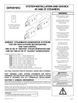
AUTOMATIC DRAIN KIT
MODEL ADK
FITS AMEREC AK/3K and AG/3G
STEAMBATH GENERATORS
SAVE THESE INSTRUCTIONS
READ ALL INSTRUCTIONS CAREFULLY
BEFORE INSTALLATION.
Amerec Steam Generators are listed by ETL. The ETL listing will remain valid so long as the ADK kit is installed per these instructions.
This ADK Kit upgrades a steamer to automatically fl ush and drain approximately 25 minutes after the bath ends. It will leave the tank empty after the fl ush and drain
cycle. An additional ADK kit is required for each steamer in a ganged system.
The Amerec Autodrain is a motorized ball valve with 3/4" NPT female pipe fi ttings on both ends. It is not directional. The motor operates on the same 200 - 240VAC
line voltage used by the steamer.
Notes:
• Check your steamer drain outlet. If your steamer has a 1/2" outlet, add a 1/2-3/4 NPT reducer to the steamer's drain pipe to allow installing this drain.
• If you are replacing a defective Autodrain motor with a black body, you will have one of two motors. Either motor may be used on the ball valve body.
Refer to the diagrams 7 and 8 for instructions on how to remove or mount the two types.
• The ADK valve is normally open: it closes during the steam bath and opens and closes during the drain/rinse cycle, then remains open until the next bath.
SECTION 1: GENERAL INFORMATION
1. Count the total number of steamers at this site.
2. If there are multiple steamers this kit must be installed on all Generators.
SECTION 2: INSPECT EXISTING LOCATION

page 2
ADK Installation and Service Instructions
4211-112 04/10/17 Technical Support: 1-425-951-1120 1-800-363-0251 [email protected]
DIAGRAM 1 DIAGRAM 2
DIAGRAM 3
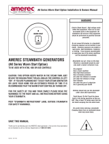
DIAGRAM 4: TYPICAL DRAIN INSTALLATIONS
Single Generator Installation
CONDUIT
4” (100mm) PIPE NIPPLE
AUTODRAIN VALV
E
We recommend installing a manual ball valve
between the steamer and the Autodrain valve to
provide a shut-off while the drain valve or piping is
disconnected for maintenance.
LEAVE 15" (380 mm)
MIN CLEARANCE FOR
ELEMENT REMOVAL

page 3
ADK Installation and Service Instructions
4211-112 04/10/17 Technical Support: 1-425-951-1120 1-800-363-0251 [email protected]
SECTION 3A: PLUMBING A SINGLE GENERATOR
All plumbing must be installed by
a licensed plumber in accordance
with local and national codes. An air
gap or check valve may also be
required by local codes)
Do Not drain the tank into the
steam room! Boiling water may
be discharged from the drain.
Draining the tank into the Steam
Room may present a scald
hazard and/or damage materials
used to construct the Steam Room.
MATERIAL (Locally available)
- (or 3/4) inch copper pipe for the tank drain See note in Section 2.
- Fittings for drain as required
- Pipe thread compound or tefl on tape
1. If the kit is being installed on an existing Generator, it will be necessary to remove enough drain plumbing
to install the motorized drain valve. See Diagrams 1, 2 & 3.
2. If this is multiple steamer system, use one Autodrain on each steamer.
IMPORTANT
Detailed drain connection information is in the Amerec 4211-1551 Installation Instructions packed
with the AK Steam Generators. The instructions must be followed to assure proper drain operation.
IMPORTANT
If additional drain valves or automatic drain valve kits are required, or if you have a steamer with a 1/2"
drain outlet, contact Technical Support 1-800-363-0251 or 1-425-1120 or at [email protected]
IMPORTANT
All Generator plumbing must be installed so that the valve motor may be removed to clear the element service clearance area shown in diagram 2.
2. Install the 4" nipple to the tank. Attach the motorized drain valve to the nipple. The drain valve should be upright and level. See diagram 1. If installing a
service shut-off ball valve (per diagram 3), mount it to the 4" nipple and add a nipple between the shut-off and the Autorain, leaving enough room to set
the cut-off valve to fully open.
IMPORTANT
The ball valve does not have directional fl ow. Do not tilt over 45 degrees.
3. Run a copper drain line from the motorized drain valve outlet to a gravity fl ow drain. Do not run the drain uphill. The drain must be connected in accordance
with local and national codes. Seal all threaded fi ttings.
IMPORTANT
All motorized drain valve outlets must be within 6 ft (1,8 m) and one 90° bend of the site gravity drain.
WARNING
SECTION 4: MOUNTING THE DRAIN VALVE'S MOTOR
The drain valve is designed so its motor may be easily removed to facilitate installation and service.
Old style motor (diagram 5):
• Before removing or installing the motor, make sure the lever (used to manually close the valve for service) is not latched open.
• To remove the motor, turn it carefully to the left until it stops then lift straight up.
• To reinstall the motor, carefully set the motor onto the valve's shaft, set the motor down onto its mounting posts, then turn the motor to the right until it locks.
If the motor is not properly secured in place, the valve may leak or fail to operate.
New style motor (diagram 6):
• To remove the motor, press the wire loop below the end of the motor to release it then lift straight up.
• To reinstall the motor, carefully set the motor onto the valve's shaft, press the wire loop below the end of the motor, then set the motor down onto its
mounting posts and release the loop. Check to be sure the motor is fi rmly locked to the valve.
If the motor is not properly secured in place, the valve may leak or fail to operate.
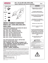
DIAGRAM 5
DIAGRAM 6
Manual Lever
Drain Open
Drain Closed
Press down then
turn right to mount
Press wire loop to release
mounting latch.
Press down on knob and
turn to manually close valve

page 4
ADK Installation and Service Instructions
4211-112 04/10/17 Technical Support: 1-425-951-1120 1-800-363-0251 [email protected]
DIAGRAM 7
DIAGRAM 8
All electrical supplies to the Steamer should be
connected before and during installation of this kit.
User Shock Hazard! 208-240V wires attached to this
Option must be routed per these instructions.
User Shock Hazard! If existing wiring is disturbed
assure that the fi nal installation conforms with
the steamer wiring diagram.
Conduit must be used when installing drain valve
to connect the valve to ground.
WARNING
SECTION 5: WIRING
For New AK Steamers:
1. Route the drain valve wires through conduit to a knock out in
the upper right corner of the steamer as shown in diagram 1.
2. Route the wires into the drain terminal block on the steamer
shelf. See diagram 7
For earlier model AK/3K and AG/3G steamers:
1. Route the drain valve wires through conduit to a knock out in
the upper right corner or a knockout just above the shelf on the
left side of the pipe end of the steamer. See diagrams 7 & 8
2. Route the wires into the drain terminal block, TB2, on the
steamer circuit board. See diagram 8
.
CONNECT DRAIN WIRES THROUGH CONDUIT
TO DRAIN TERMINAL BLOCK IN STEAMER:
CONNECT DRAIN WIRES THROUGH CONDUIT
TO DRAIN TERMINAL BLOCK ON CIRCUIT BOARD:
TB2

page 5
ADK Installation and Service Instructions
4211-112 04/10/17 Technical Support: 1-425-951-1120 1-800-363-0251 [email protected]
1. Assure power and water are on.
2. Turn on the Generator(s) using the owner's control. Allow the tank(s) to fi ll completely. Adjust the bath temperature to a point at least 10°F (6C) above the
current steam room temperature to ensure the steamer begins heating the water.
3. Turn off the Generator(s) using the owner's control.
4. Approximately 25 minutes after the steam bath stops, the drain will open and close a few times and water will be added to the generator as needed to cool
the water and drain the tank; this could take up to 15 minutes. Once the drain cycle is complete, the tank will remain empty until the next bath. No water
should come out the steam head.
The unit is now ready for operation.
SECTION 6: OPERATIONAL TEST
There are no user serviceable parts in the Generator. All repair should be performed by a qualifi ed service person. For additional assistance or the factory
authorized service person nearest you call Technical Support at 1-800-363-0251. The Troubleshooting Guide below is meant as a general aid only. Follow
ACTION TO BE TAKEN in order until the problem is resolved.
SECTION 7: TROUBLESHOOTING GUIDE
PO Box 2258
Woodinville, WA 98062
Phone: 1-800-363-0251
1-425-951-1120
FAX: 425-951-1130
NOTE: Make sure the motor is in the fully closed position and not sticking against an obstruction.
SYMPTOMS PROBABLE CAUSES ACTION TO BE TAKEN
Drain Valve Leaks Motor not secured to valve
or
Valve part way open
or
Debris in valve
or
Faulty PCA (Circuit Board)
Remount motor per section 4
Clean Valve
Check voltage to drain valve (check wire to wire).
If no voltage is present, check 1A fuse on PCA
If fuse is good, PCA may be faulty
Water does not run out the drain Manual drain valve closed
or
Valve or drain piping plugged
Make sure any manual valves in the drain piping are open
Clean outlet, valves and piping .
Water runs out steam outlet during drain cycle Faulty PCA PCA or other steamer parts faulty.
Water runs out the drain while the
steam bath is turned off
Water valve leaking
or stuck open
Contact Technical Support for assistance
for further assistance, contact us at
/