Page is loading ...

AX INSTALLATION AND SERVICE INSTRUCTIONS
4211-119 09/18/20 Technical Support 1-425-951-1120 1-800-363-0251 support@amerec.com Page 1 of 18
These instructions apply to the
AX4.5, AX6, AX7.5, AX9, AX11 and AX14
Amerec Steamers With Elite or Pure 2.0 controls
208V and 240V 1/3 Phase Models.
(Also use 240V models for 415V~N3 installations)
SAVE THESE INSTRUCTIONS
READ ALL INSTRUCTIONS CAREFULLY BEFORE INSTALLATION.
POST SAFETY "WARNING" LABEL OUTSIDE STEAMBATH. LABEL
SHOULD BE POSTED ON OR ADJACENT TO DOOR TO STEAM
ROOM IN COMMERCIAL INSTALLATIONS.
SECTION 1: GENERAL INFORMATION
Amerec steam generators are tested by Intertek-ETL Laboratory. The
steam generators come assembled and ready for installation. Check that
the size and rating of the generator is suitable for your application, refer to
the AX Steam Room Sizing and Rough-in Guide (Amerec doc 4211-36).
The AX steamers may be connected as a ganged system where one Steamer controls one or two other steamers.
Bath controls connect to the primary steamer and the primary steamer connects to the second steamer (and third
steamer, if installed). This provides more power for large rooms and light commercial use. Note: An Elite control
is required with a ganged system! See appendix to this document for details.
We recommend choosing steamers which are closely matched in power. The highest kW steamer should be the
primary unit. Each steamer should have its own automatic drain.
For commercial use, we recommend checking with your local inspectors to confirm the AX system is acceptable for
your use. Many jurisdictions will require an ASME boiler for commercial use: AX steamers are not boilers.
Note: The AX steamer may be configured for single or three phase power during installation
An exhaust fan installed outside the steam room is strongly recommended.to remove excess steam from the
bathroom or shower area.
ELITE
AX STEAM GENERATOR
PURE 2.0
CAUTION
Electrical grounding is required on all
AMEREC Steam bath Generators.
All electrical supplies should be
disconnected when servicing generator.
All wiring must be installed by a licensed
electrical contractor in accordance with
local and national codes.
All plumbing must be installed by a
licensed plumber in accordance with all
applicable local and national codes.
AX series generators are
for indoor use only.
AX series generators are not for
space heating purposes.
Be certain that steam bath enclosures
are properly sealed to avoid water
damage from escaping steam. It is
recommended that 100% silicone caulk
be used to seal all pipes and fittings.
Steam must be prevented from escaping
into the wall cavity.
Never shut off the water to a
steam generator that is in use.
Electric Shock Hazard - High voltage
exists within this equipment. There
are no user serviceable parts in this
equipment.

AX INSTALLATION AND SERVICE INSTRUCTIONS
4211-119 09/18/20 Technical Support 1-425-951-1120 1-800-363-0251 support@amerec.com Page 2 of 18
TABLE OF CONTENTS
Section Description Page
Important Safety Instruction 3-6
1 Mounting the Generator 7-8
2 Water Quality Requirements 8
3 Plumbing Instructions 9-11
4 Wiring Instructions 12
5 Bath Control Installation 13-14
6 Initial Start 14-15
7 Contact Information 15
Electrical Information Chart 16
Wiring Diagrams 17-18
Appendix 1: Systems Installation

AX INSTALLATION AND SERVICE INSTRUCTIONS
4211-119 09/18/20 Technical Support 1-425-951-1120 1-800-363-0251 support@amerec.com Page 3 of 18
WARNING
Thank you for purchasing your new AMEREC AX steam generator.
If we can be of any assistance do not hesitate to call our Technical Support at 1-800-363-0251.
FOR THE SAFETY OF YOU AND YOUR FAMILY OR CUSTOMERS, PLEASE READ THE
FOLLOWING WARNINGS AND ALL INSTRUCTIONS BEFORE USING YOUR STEAMBATH.
POST "STEAMBATH INSTRUCTIONS" LABEL OUTSIDE STEAMBATH FOR SAFETY WARNINGS.
SAVE THIS MANUAL
FOR THE SAFETY OF YOU AND YOUR FAMILY OR CUSTOMERS, PLEASE READ THE
FOLLOWING WARNINGS AND ALL INSTRUCTIONS BEFORE USING YOUR STEAMBATH.
POST "STEAMBATH INSTRUCTIONS" LABEL OUTSIDE STEAMBATH FOR SAFETY WARNINGS.
Electric Shock Hazard - High voltage exists within this equipment. Disconnect all electrical power before
servicing the generator. All installation and service to this equipment should be performed by qualified
licensed personnel in accordance with local and national codes. There are no user serviceable parts in
this equipment.
Electrical grounding is required on all AMEREC steambath generators. The generator is designed for hookup with
copper wire only, 75°C or better.
Wire the controls exactly as described. Do not connect any additional wiring or power supplies to the controls or
their terminals in the generator.
Service only by authorized personnel!
All plumbing must be installed by a licensed plumber in accordance with all applicable local and national codes.
Install indoors only. Protect from freezing. Generator must be level side to side and end to end.
The pressure relief valve and generator drain must be installed in such a fashion that the risk of scalding is reduced
to a minimum. Draining these outlets into the steam room may present a scald hazard and may damage materials
used to construct the room.
Danger To reduce the risk of explosions, do not interconnect t steam lines!!
Caution The steam outlet carries hot vapor! A separate steam line is required for each steam outlet.
Do not connect a valve or shut-off in the steam line! Avoid traps and valleys in the steam line where
water could collect and cause a steam blockage. The hot steam line must be insulated against user contact.
Do not install the steam head near a bench or where steam may spray or where condensation will drip on the user
as this will present a scald hazard.
Be certain that steambath enclosures are properly sealed to avoid water damage from escaping steam. It is
recommended that 100% silicone caulk be used to seal all pipes and fittings. Steam must be prevented from
escaping into the wall cavity. Centering the steam pipe is critical in rooms made of plastic, acrylic, resin, fiberglass
or similar materials. Allowing the steam pipe to touch materials not rated 240°F (115°c) or higher will result in
damage to these materials.

AX INSTALLATION AND SERVICE INSTRUCTIONS
4211-119 09/18/20 Technical Support 1-425-951-1120 1-800-363-0251 support@amerec.com Page 4 of 18
AVERTISSMENT
Merci pour l'achat de votre nouveau AMEREC AX générateur de vapeur.
Si nous pouvons vous être utiles n'hésitez pas à appeler notre assistance technique au 1-800-363-0251.
POUR LE SËCURITË DE VOTRE FAMILLE ER VOUS OU CLIENTS, VEUILLEZ
LIRE LES AVERTISSEMENTS SUIVANTS ET TOUTES LES INSTRUCTIONS AVANT
D'UTILISER VOTRE BAIN DE VAPEUR.
POST "BAIN DE VAPEUR" LABEL HORS D UN BAIN DE d'INSTRUCTIONS
POUR DES AVERTISSEMENTS EN MATIÈRE DE SÉCURITÉ.
ENREISTREZ CE MANUEL
POUR LA SËCURITË DE VOTRE FAMILLE ET VOUS OU VOS CLIENTS, VEUILLEZ LIRE
APRèS AVERTISSEMENTS ET TOUTES LES INSTRUCTIONS AVANT D'UTILISER VOTRE BAIN DE VAPEUR.
POST "BAIN DE VAPEUR" LABEL HORS D' UN BAIN DE VAPEUR D'INSTRUCTIONS POUR DES
AVERTISSEMENTS EN MATIÈRE DE SËCURITË.
Risque de choc électrique - Haute tension existe au sein de ce matériel. Débranchez toute source d'alimentation
avant de procéder à l'entretien du générateur. Toutes les instructions d'installation et service à cet équipement doit
être effectuée par du personnel autorisé qualifié conformément aux codes locaux et nationaux. Il n'y a pas de pièce
réparable par l'utilisateur à cet équipement.
Mise à la terre électrique est requis sur tous les générateurs bain de vapeur AMEREC. Le générateur est conçu pour connecter
un fil de cuivre uniquement, 75 °C ou mieux.
Câbler le contrôle très exactement comme indiqué. Ne connectez aucun câblage supplémentaire ou blocs d'alimentation pour
les commandes ou leurs terminaux dans le générateur.
Service uniquement par le personnel autorisé!
Toute la tuyauterie doit être installé par un plombier sous licence conformément à tous les codes locaux et nationaux
applicables.
Installer à l'intérieur uniquement. Protéger du gel. Générateur doit être mise à niveau latérale et l'extrémité à l'autre.
La valve de limitation de pression et purge du générateur doit être installé de telle façon que le risque de brûlure est réduit à un
minimum. Vidange de ces prises dans la salle de vapeur peut présenter un risque de brûlure et peut endommager les matériaux
utilisés pour construire la salle.
Danger Pour réduire les risques d'explosion, ne pas connecter les conduites de vapeur t!!
Attention La sortie vapeur transporte vapeur chaude ! Une conduite de vapeur distincte est requise pour chaque
sortie vapeur. Ne connectez pas une valve ou l'arrêter dans la conduite de vapeur! Éviter les pièges et les vallées
dans la conduite de vapeur où l'eau pourrait recueillir et provoquer un blocage de vapeur. La vapeur chaude ligne doit être
isolée par rapport au contact de l'utilisateur.
Ne pas installer la tête de vapeur près d'un banc ou où la vapeur peut pulvériser ou où la condensation s'égoutter sur l'utilisateur
comme cela présentera un risque de brûlure.
Etre certain que le bain de vapeur boîtiers sont étanches afin d'éviter les dégâts d'eau de s'échapper la vapeur. Il est
recommandé que 100% mastic au silicone utilisée pour obturer tous les raccords et tuyaux. La vapeur doit être empêché de
s'échapper dans la cavité du mur. Centrage du tube à vapeur est critique dans les chambres faites de plastique, de l'acrylique,
résine, la fibre de verre ou des matériaux similaires. Permettant le tube à vapeur pour toucher les matériaux non coté 115°C ou
plus aura pour effet d'endommager ces matériaux.

AX INSTALLATION AND SERVICE INSTRUCTIONS
4211-119 09/18/20 Technical Support 1-425-951-1120 1-800-363-0251 support@amerec.com Page 5 of 18
POST "WARNING LABEL OUTSIDE STEAMBATH FOR SAFETY WARNINGS
Étiquette d'avertissement "Extérieur poste baiin de vapeur pour les avertissements relatifs à la sécurité

AX INSTALLATION AND SERVICE INSTRUCTIONS
4211-119 09/18/20 Technical Support 1-425-951-1120 1-800-363-0251 support@amerec.com Page 6 of 18
IMPORTANT USER SAFETY INSTRUCTIONS
1. READ AND FOLLOW ALL INSTRUCTIONS.—SAVE THESE INSTRUCTIONS!
2. The steam bath is not intended for use by anyone (including children) with reduced physical, sensory or mental capabilities or who lack
experience or knowledge, unless they have supervision or training on the use of the steam bath by a person responsible for their safety.
3. WARNING - To reduce the risk of injury, do not permit children to use this product unless they are closely supervised at all times. Ensure
they do not play in the steam bath.
4. WARNING - To reduce the risk of injury:
a. The wet surfaces of steam enclosures may be slippery. Use care when entering or leaving.
b. The steam head is hot. Do not touch the steam head and avoid the steam near the steam head.
c. Prolonged use of the steam system can raise excessively the internal human body temperature and impair the body’s ability to
regulate its internal temperature (hyperthermia). Limit your use of steam to 10 to 15 minutes until you are certain of your body’s
reaction.
d. Excessive temperatures have a high potential for causing fetal damage during the early months of pregnancy. Pregnant or possibly
pregnant women should consult a physician regarding correct exposure.
e. Obese persons and persons with a history of heart disease, low or high blood pressure, circulatory system problems, or diabetes
should consult a physician before using a steam bath.
f. Persons using medication should consult a physician before using a steam bath since some medication may induce drowsiness while
other medications may affect heart rate, blood pressure and circulation.
5. WARNING - Hyperthermia occurs when the internal temperature of the body reaches a level several degrees above the normal body
temperature of 37°C. The symptoms of hyperthermia include an increase in the internal temperature of the body, dizziness, lethargy,
drowsiness and fainting. The effects of hyperthermia include:
a. Failure to perceive heat:
b. Failure to recognize the need to exit the steam bath:
c. Unawareness of impending risk:
d. Fetal damage in pregnant women:
e. Physical inability to exit the steam bath: and
f. Unconsciousness.
6. WARNING - The use of alcohol, drugs or medication can greatly increase the risk of hyperthermia
1. Lire et suivre toutes les instructions. -- Conservez ces instructions !
2. Le bain de vapeur n'est pas destiné à être utilisé par toute personne (y compris les enfants) avec toutes leurs capacités physiques,
sensorielles ou mentales ou qui manquent d'expérience ou de connaissances, à moins qu'ils aient la supervision ou de la formation sur
l'utilisation du bain de vapeur par une personne responsable de leur sécurité.
3. Avertissement : Pour réduire les risques de blessures, ne pas permettre aux enfants d'utiliser ce produit, sauf s'ils sont étroitement
surveillés en tout temps. S'assurer qu'ils ne jouent pas dans le bain de vapeur.
4. Avertissement : pour limiter les risques de blessure :
a. Les surfaces mouillées de boîtiers de vapeur peut être glissant. Soyez prudent lorsque vous entrant ou sortant.
b. La tête de vapeur est chaud. Ne pas toucher la tête de vapeur et éviter la vapeur près de la tête de vapeur.
c. Une utilisation prolongée de la chaudière à vapeur peut augmenter excessivement la température du corps humain et d interne
nuisent à la capacité du corps de régler sa température interne (hyperthermie). Limitez votre consommation de vapeur pour 10 à 15
minutes jusqu'à ce que vous soyez certain de la réaction de votre corps.
d. Des températures excessives ont un haut potentiel de causer de dommages foetaux pendant les premiers mois de la grossesse.
Enceinte ou peut-être les femmes enceintes devraient consulter un médecin au sujet de l'exposition correcte.
e. Les personnes obèses et les personnes ayant des antécédents de maladie du coeur, tension artérielle basse ou élevée, des
problèmes du système circulatoire ou de diabète devraient consulter un médecin avant d'utiliser un bain de vapeur.
f. Les personnes qui utilisent ces médicaments devraient consulter un médecin avant d'utiliser un bain à vapeur depuis quelques
médicaments peut induire une somnolence tandis que d'autres médicaments peuvent affecter la fréquence cardiaque, la tension
artérielle et de la circulation.
5. Avertissement - L'hyperthermie survient lorsque la température interne du corps atteint un niveau à plusieurs degrés au-dessus de la
normale de la température corporelle de 37 °C. Les symptômes de l'hyperthermie comprennent une augmentation de la température
interne du corps, sensation vertigineuse, léthargie, somnolence et d'évanouissement. Les effets de l'hyperthermie comprennent :
a. L'incapacité de percevoir la chaleur
b. L'incapacité à reconnaître la nécessité de quitter le bain de vapeur :
c. La méconnaissance de l'imminence d'un risque :
d. Dommages au foetus chez les femmes enceintes :
e. Incapacité physique pour quitter le bain de vapeur : et
f. L'inconscience.
6. Avertissement - La consommation d'alcool, de drogues ou de médicaments peut augmenter considérablement le risque d'une
hyperthermie

AX INSTALLATION AND SERVICE INSTRUCTIONS
4211-119 09/18/20 Technical Support 1-425-951-1120 1-800-363-0251 support@amerec.com Page 7 of 18
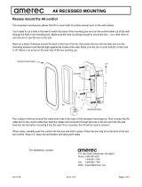
SECTION 1: MOUNTING THE STEAM GENERATOR
DIAGRAM 1
DIAGRAM 2
The AMEREC steam generator can be hung on a wall or sit on its base. The best mounting location will satisfy all
or most of the following:
WARNING: The generator will not operate properly, unless it is mounted level with the arrows pointed up
1. The generator should be installed in a dry, well ventilated area. Suggested locations are under a vanity, in
a closet, attic, crawl space or basement. Do not mount outdoors.
2. If the generator will be in an area difficult to access, the water supply should be equipped with easily access
water shut-off valve in case of emergency.
3. If the steam line is in an area where the temperature will be below 39°F (4°C) best results can be obtained by
insulating the steam pipe. Do Not mount the generator in an area subject to freezing.
4. The generator must be mounted in a minimum 7 cubic feet (0,2 cubic meter) space.
5. The location must allow access for service! Provide clearance for plumbing and electrical service and for
element removal. See Diagram 1.
6. The steam line should slope to allow condensation to drain. The mounting location should minimize the number
of bends and elbows in the steam line
7. The mounting location should allow for a drain hook up.
8. The steam line should be less than 20 ft (6 m) long; 10 ft (3 m) is preferred. Steam lines over 20ft (6 m) long
should be insulated.
WARNING
• There must be no dips or valleys in the steam line.
• Install the steam head so as to avoid potential user direct contact with the steam or where condensation may
drip on the user as this may present a scald hazard.
• Do Not install any valves or other shut-off devices in the steam line!
• Do Not interconnect steam lines! A separate steam line is required for each generator!
• Do Not connect the drain line to the steam line or allow the drain empty into the steam room!
• Do Not connect the pressure relief valve into the steam line or vent it where someone nearby could be scalded!
Do Not allow the relief valve to vent into the steam room!
Leave 13” [330 mm]
Service Clearance
14.5” [368 mm]
13.2”
[335,3 mm]
0.8”
[20,3 mm]
Steamer must be level
End-to-End and
Front to Back

AX INSTALLATION AND SERVICE INSTRUCTIONS
4211-119 09/18/20 Technical Support 1-425-951-1120 1-800-363-0251 support@amerec.com Page 8 of 18
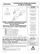
SECTION 1: MOUNTING THE STEAM GENERATOR (continued)
1. WALL MOUNTING: Remove the side cover. Note the location of the
mounting holes on the back of the generator. The screws must set
directly into studs or equivalent supports. Drill pilot holes on 14-1/2”
(368 mm) centers and install the two #10 1½" screws, provided.
See at right.
a) Carefully hang the generator on the two screws. Tighten the
screws.
b) The generator may be further secured with two screws
mounted on the same 14-1/2” (368 mm) centers as shown.
c) Replace the front cover with its four screws.
2. FLOOR MOUNTING:
a) In general, the width of the unit allows it to sit on a shelf, across
the ceiling joists or on a floor. The generator must be restrained
from moving. Normally, the piping will provide adequate
support. If not, additional support must be provided.
b) All floor installed generators must provide for routine draining of
the tank and for draining the safety valve’s outlet.
SECTION 2: WATER QUALITY REQUIREMENTS
The nature of a boiler or steam bath generator requires testing of the
feedwater to avoid potential high concentrations of impurities which can
cause a deposit or scale to form on the internal surfaces. This deposit
or scale can interfere with the equipment's proper operation and even
cause premature boiler or generator failure. Concentration of impurities
is generally controlled by treating the feedwater and or "blowing down"
the generator or boiler when it is not heating. The "blow down" process involves removing a portion of the tank
water with high solid concentration and replacing it with makeup water.
This is particularly important in areas with high calcium levels and other water quality problems. Calcium build-up
can cause poor steamer performance and damage the heating elements!
Be especially careful to prevent foaming in the steamer’s water! Foaming water will affect the water level
measuring systems in steamers and boilers, causing operation problems and possibly leading to early element
failures!
To insure proper operation, the water supply should be tested prior to operating the equipment. There are several
treatment processes which can be used if you have a problem with hard water. A local reliable water treatment
company can recommend the appropriate treatment if required. The recommended feedwater quality is listed on
the next page.
Recommended Feedwater Quality
Hardness 10 – 30 ppm - (0.5 - 1.75 gpg)
T-Alkalinity 150 – 700 ppm - (8.75 - 40.8 gpg)
Silica Range 15 – 25 ppm - (1.28 - 1.45 gpg)
PH (strength of alkalinity) 10.5 -- 11.5
WALL MOUNTING
14.5” [368 mm]
14.5” [368 mm]

AX INSTALLATION AND SERVICE INSTRUCTIONS
4211-119 09/18/20 Technical Support 1-425-951-1120 1-800-363-0251 support@amerec.com Page 9 of 18
IMPORTANT!
Regular maintenance will help your steamer work properly for a long time. Check for leaks,
loose or damaged wires, signs of corrosion and calcium build up in the tank on the level probe.
SECTION 3: PLUMBING INSTRUCTIONS
All plumbing shall be installed by a licensed plumber and conform with local & national codes.
Materials Needed:
• 3/8NPT, 1/2NPT and 3/4NPT unions: recommended to allow easy disconnect of steamer for servicing
• 3/8" copper pipe and 3/8” male NPT adapter for the water supply to the generator.
• 3/8" water supply shut-off valve.
• 3/8" supply valve housing and filter (optional depending on local water conditions).
• 1/2" copper pipe and (2) 1/2" male NPT adapters for the steam line between the generator and the steam room
outlet.
• 3/4" copper pipe and 3/4" male NPT adapter for the tank drain.
• 3/4" copper pipe, fittings, and a union for the Pressure Relief Safety Valve drain.
• Tube 100% silicone caulk.
• Pipe compound suitable for drinking water use at more than 212°F (100°C).
1. INSTALL WATER LINE Connect a cold water line to the generators water valve. The valve input is 3/8” NPT. A
shut-off valve should be placed in the line for each generator to allow easier servicing later, if needed, and for
emergency shut-off. Make sure the shut-off is open, providing water to the generator before first turning the on.
IMPORTANT
• Water pressure required: 20-100 psi (138-690 kPa)
• If the generator is mounted in a place difficult for the homeowner to access, the water supply
shut-off valve should be located where it can be quickly accessed in an emergency.
• Do not use a saddle valve or saddle fitting for the water shut-off valve.
• Flush water supply line before final hookup.
2. INSTALL STEAM LINE
a) At the generator: Install a 1/2" male NPT sweat adapter directly into the tank. Install a 1/2" union in the steam
line to allow easy disconnection for later servicing. Note: There must be no valves, shut offs or restrictions in
the steam line!
b) Run the 1/2" copper steam line from the generator to the steam room. Refer to SECTION 2: MOUNTING THE
STEAM GENERATOR and Diagrams 3a and 3b.
• The steam line must slope to allow condensation to drain into the tank or room.
• There must be no dips in the steam line. Low areas may collect condensation and cause faulty operation or
cause hot water to spit into the room.
c) The steam line should enter the steam room 18” (460 mm) above the floor or at least 12” (305 mm) above a tub
rim or ledge. The steam line outlet should be at least 6” (150 mm) from other steam heads to either side and
12” (305 mm) from walls or other surfaces to either side. See Diagrams 4, 5 and 6.

AX INSTALLATION AND SERVICE INSTRUCTIONS
4211-119 09/18/20 Technical Support 1-425-951-1120 1-800-363-0251 support@amerec.com Page 10 of 18
SECTION 3: PLUMBING INSTRUCTIONS (continued)
Diagram 3a
Diagram 3b
Note: See Diagram 6 for a typical installation. Additional steam heads may be added to any installation to reduce
steam noise or to provide more steam dispersion around a large room. For large AX14 steamers, we recommend
using 2 steam heads to reduce the noise level while steaming.
Note: if steam vents are too close to other surfaces, the steam may be cooled and the surfaces damaged.
d) At the steam room: Drill/prepare a 1-3/8” (35 mm) hole for the
steam line entry. Center the 1/2" copper steam pipe in the hole.
See Diagram 4.
• Terminate the steam line with a 1/2" NPT male adapter.
• Stub the line out into the room 3/8” (9,5 mm) from the
finished surface.
• Secure the steam line to a structural member.
3. INSTALL STEAM HEAD INSULATOR: Fill in gap (using 100%
Silicone caulk between steam pipe and finished wall surface at
point of entry (see Diagram 4). Apply silicone caulk to the finished
wall side of the steam head insulator (see Diagram 5) and screw on
hand tight until it is flush with the wall with the opening pointing
down. If a hand tight fit does not align with the opening pointing
down, use Teflon tape on the steam line threads to adjust the fit.
DIAGRAM 4
3/8”
(9,5 mm)
FROM
WALL
1/2 NPT
1-3/8”
(35 mm)
HOLE

AX INSTALLATION AND SERVICE INSTRUCTIONS
4211-119 09/18/20 Technical Support 1-425-951-1120 1-800-363-0251 support@amerec.com Page 11 of 18
SECTION 3: PLUMBING INSTRUCTIONS (continued)
4. INSTALL STEAM HEAD: Slide the steam head on until it rests firmly
against the finished wall. Tighten the hex head screw underneath the
steam head to secure it in place with the Allen wrench provided. The
steam head should be level with its fragrance reservoir at the top. See
Diagrams 4 and 6.
IMPORTANT
All fixture holes must be sealed with 100% silicon caulk
to avoid moisture damage within walls. Check all of the
standard fixtures in the steam room.
5. INSTALL PRESSURE RELIEF SAFETY VALVE: Install the pressure relief valve into its port on the generator.
Install the safety valve within 6” [150] mm of the generator. Run a 3/4" copper line from the valve to a gravity flow
drain. The pressure relief valve outlet must drain in accordance with local and national codes.
AUTODRAIN All generators must have a drain valve installed to
allow draining the tank for cleaning and maintenance. A manual
ball valve is supplied. An electronic ball valve is available in the
ADX Autodrain option. When installed, Autodrain automatically
rinses and empties the steam tank approximately 1 hour after a
steam bath stops. This cleans the tank to reduce problems
caused by poor water quality and ensures every steam bath starts
with clean, fresh water. Contact Amerec Technical Support for
more information. Suppor[email protected]
or 1-425-951-1120
or at 1-800-363-0251
6. INSTALL DRAIN VALVE: Install 3/4" NPT pipe nipple directly
into the tank as shown in Diagram 7. Install a 3/4" ball valve or an
Autodrain on the nipple then add another nipple to the outlet of
the valve. Add a union to the outlet nipple to allow easy discon-
nection during servicing. Run a 3/4" copper line from the union
to a gravity flow drain. The drain must be connected in accordance with local and national codes.
DIAGRAM 5
DIAGRAM 6
DIAGRAM 7
12” [305 mm]
6”
[150 mm]
ii
18”
[460 mm]
minimum
Shown with optional 2
nd
steam outlet.
HEATING ELEMENT
ACCESS
MANUAL VALVE
AUTODRAIN
VALVE
3” [76 mm] PIPE
CONDUIT
OR
SILICONE
BACK
SIDE
Diagrams 6 and 8 show the optional Autodrain valve

AX INSTALLATION AND SERVICE INSTRUCTIONS
4211-119 09/18/20 Technical Support 1-425-951-1120 1-800-363-0251 support@amerec.com Page 12 of 18
SECTION 3: PLUMBING INSTRUCTIONS (continued)
IMPORTANT
All drain lines must run downhill, away from the steam generator! Also see Diagram 3.
• Do not run the drain uphill.
• Do not drain the safety valve into the steam line!
• Do not drain the safety valve into the steam room!
Draining the tank into the steam room may present a
scald hazard or damage the materials used to construct
the steam room.
• Do not drain into the steam room!
7. CONNECT AUTODRAIN: Connect the autodrain wires
through ½ in conduit (provided) and secure the conduit to the
chassis hole. Connect the drain wires to the terminal block
provided next to the steamer’s ground lug. See diagram 8.
SECTION 4: WIRING INSTRUCTIONS
ALSO SEE ELECTRICAL INFORMATION CHART AND WIRING DIAGRAMS
1. ELECTRICAL ROUGH-IN: Size wire for the generator as required by local or national codes. See the electrical
information on page 13 for further information. Use copper wire only. Leave 4 ft (1,2 m) of slack wire at generator
location for finish hookup. Connect the generator to a dedicated circuit breaker. A GFI device is usually not required
by safety agencies. One may be installed if required by local codes or the owner. A GFI device will tend to nuisance
trip due to heater element aging.
a. Route the copper supply wire with appropriate strain relief through the hole marked POWER ENTRY.
b. Connect the supply wires to the power terminal block as indicated on the wire diagram for your voltage and
phase. This may require moving factory installed jumper. Do not change the steamer’s internal jumpers or
wiring. Only the supply wiring side of the terminal blocks require configuration by the installer.
c. Connect the Earth wire to the copper Earth ground lug.
d. Cover the supply wires inside the steamer with a protective mesh or similar material to protect them
from water valve heating.
2. ELECTRICAL INFORMATION The AX steamers are available in 2 basic versions, one for 208V (intended for
208VAC single and three phase for North American use) and 240V (intended for all other installations. The 240V
models are rated at 240VAC and may be used on 208 to 240V single phase Line-to-Line or 208 to 240V~N (Line-
to-Neutral) or 208V to 240V three phase Delta without Neutral or for Y-connected three phase 380 to 415V~N3.
All Units are factory wired for single phase installation. The installer may change the input to three phase or three
phase with Neutral during initial installation (see the wiring diagrams on page 18).
The National Electrical Code (NEC) limits a steamer’s current to 48 Amps so in some cases, two separate power
supplies are required: AX11 & AX14 208V single phase and AX14 240V single phase.
See page 18 for Mains Wiring Details. Note: jumpers shown are supplied with the steamer.
DIAGRAM 8
(CONDUIT NOT SHOWN)

AX INSTALLATION AND SERVICE INSTRUCTIONS
4211-119 09/18/20 Technical Support 1-425-951-1120 1-800-363-0251 support@amerec.com Page 13 of 18
Electrical Information
Model
Rated
VAC
Watts
Room Size cu ft
Room Size cu m
min Max min
Max
AX4.5
208
4500 60 90 1.70 2.55
240
415~N3
AX6
208
6000 80 150 2.27 4.25
240
415~N3
AX7.5
208
7510
100 200 2.83 5.66 240
7500
415~N3
AX9
208
9000 150 300 4.25 8.50
240
415~N3
AX11
208
11250
200 400 5.66 11.30
240
11000
415~N3
AX14
208 13750
350 550 9.91 15.60
240
14000
415~N3
Model
208 22 30 12 20
240 19 30 11 15
415~N3 6 15
208 29 40 17 30
240 25 40 14 20
415~N3 8 15
208 36 50 21 30
240 31 40 18 30
415~N3 10 15
208 43 60 25 40
240 38 50 22 30
415~N3 13 20
208 18 & 36 30 & 50 31 40
240 46 60 26 40
415~N3 16 20
208 24 & 42 30 & 60 38 50
240 21 & 38 30 & 60 34 50
415~N3 19 30
Rated
VAC
Amps
1 phz
Breaker
Amps3
phz
Breaker
AX4.5
AX6
AX7.5
AX9
AX11
AX14
240V models may be used at 208 to 240V.
Operating on voltages lower than 240V will result
in reduced wattage. Contact Technical Support for
further information.
Single phase 240V models are designed for North
American 240V line to line Mains voltages (without
Neutral) or 240V~N international voltages.
Three phase 240V models may be wired during
installation for a 240V delta configuration or for a
415V~N3 Y-configuration. Neutral must be supplied
for 415V!
NEC Electrical code restrictions limit Mains
current to 48A. Some single-phase models
require two separate Mains circuits to remain
below 48A by splitting the heating load
Also refer to the wiring diagrams on pages 17
and 18 for more information on connecting your
steamer.
Notes:
All steamers must be on a dedicated branch
circuit!
Use only copper wire rated 600V~ and 75°C
minimum
All models require Earth ground
All line voltage must be more than 195V~
while the steamer is heating
Steamers must be connected to a means for
disconnecting all supply voltages
All AX14 and 208V AX11 single phase
require two Mains supplies
We recommend ceilings height be 8 ft (2,4m)
max. Higher ceilings may cause sitting area
to be uncomfortably cool.

AX INSTALLATION AND SERVICE INSTRUCTIONS
4211-119 09/18/20 Technical Support 1-425-951-1120 1-800-363-0251 support@amerec.com Page 14 of 18
FLOOR
SECTION 5. BATH CONTROLS
1. TEMPERATURE SENSOR CABLE ROUGH-IN (low voltage) It is required that the sensor be mounted in the
steam room, but not directly over the steam dispersion head or near the door. The sensor should be located in a
wall 6” (150 mm) below the ceiling but no more than 7 ft (2,1M) above the floor. String the sensor cable from the
sensor location through 1/2:” (12 mm) holes in the wall studs or ceiling joists to the generator location. Drill a clean
7/8: (22 mm) hole through the steam room wall at the sensor location. Leave 12” (305 mm) of slack at the sensor
location. See Diagram 9.
Note: Do not staple through or damage cable.
Use factory supplied cables only.
INSTALL THE TEMPERATURE SENSOR ASSEMBLY
inside the steam room. A 7/8” (22 mm) hole should already
be in the steam room wall with the cable ready.
Make sure the sensor is not directly over the steam outlet
head or near the door. The sensor should be located in a wall
6” (150 mm) below the ceiling but no more than 7ft (2,1 m)
above the floor. Carefully connect the sensor cable to the
sensor. The cable end should slide into place and lock.
Run a light bead of silicone around the back surface of the sensor and slide it into the wall with the metal sensor
tube pointed down. Tape the sensor to the wall until the silicone has set-up.
Connect the steam generator end of the cable to the short adapter cable (4-pin modular plug to 2 pin sensor cable
jack) and plug the adapter into the NTC jack on the steamer board (located along the top edge of the steamer’s
circuit board, at the far left of the 4 black jacks). (See diagram 10)
2. CONTROL CABLE ROUGH-IN (low voltage) A 50 ft (15,2 m) 4 wire Cat5 cable is provided for connecting the
PURE 2.0 or ELITE control to the steamer. The PURE 2.0 and ELITE controls may be mounted inside or outside
the steam room. String the control cable from the control location through 1/2” (13 mm) holes in the wall studs or
ceiling joists to the generator. Note: Do not staple through or damage cable. Use factory supplied cables only.
Run the cable end through a 1” (25,4 mm) hole in the wall at the control mounting location. One PURE 2.0 or ELITE
control is required; a second may also be connected. Controls should typically be mounted 5 feet (1,5 m) above the
floor outside the steam room or at a height comfortable for viewing inside the room while having a steam bath. See
control mounting section for more information.
3. INSTALL THE ELITE or PURE 2.0 CONTROL inside or outside the steam room using the control
cable installed in section 5, step 4. If mounting to a smooth, flat wall, the adhesive pad provided will
work well to mount the control and seal the cable hole. The adhesive will stick to the wall quickly so be
sure to accurately place and level the control before attaching it to the wall!
Your Elite control comes with a plated trim piece; many finishes are available. These
trim pieces also fit the Pure 2.0. Contact Sales or Support for further information. If
using a trim piece, slide the plated trim piece over the back of the control before
mounting the control. Mounting the control will keep the trim in place.
DIAGRAM 9
SENSOR
CABLE
7/8’
22 mm
HOLE
WALL
SENSOR
TIP MUST
POINT
DOWN
SEAL BACK WITH
SILICONE
Recommended: Locate controls 5 ft (1,5 m) above floor outside
the steam room. Controls mounted inside the room should be
set to a height comfortable for use while having a steam bath.

AX INSTALLATION AND SERVICE INSTRUCTIONS
4211-119 09/18/20 Technical Support 1-425-951-1120 1-800-363-0251 support@amerec.com Page 15 of 18
SECTION 5. BATH CONTROLS (continued)
If the surface is uneven or has grout lines, we recommend using a small amount of silicone to mount the control. If
using silicone, run a bead around the control’s cable end and another bead around the back of the control as
shown here. Then tape in place on the wall until the silicone has set up. Note: and mount in the same manner.
If using the adhesive pad, it will stick to the wall quickly so be sure to
accurately place and level the control before attaching it to the wall!
Be sure to carefully level the control while mounting!
Note the Elite and Pure 2.0 controls have the same case:
• The control’s cable end is at the bottom of the control and a cut mark
on the back indicates the top of the control!
• The Pure 2.0’s orientation can also be seen by viewing the glass:
all the white markings are on the bottom half of the glass.
4. CONNECT THE CONTROL CABLE TO THE STEAMER with the Mains
voltage turned off. The control cable should be plugged into the one of the
four jacks in the middle of the steamer circuit board (see Diagram 10 and
the low voltage wiring diagram on page 17).
DIAGRAM 10
CONNECT CONTROLS TO ANY OF THE 4 JACKS
IN THE CENTER OF THE CIRCUIT BOARD.
CONFIGURATION SWITCH
AX STEAMER – RIGHT HAND END
CONNECT TEMPERATURE SENSOR TO JACK AT THE
LEFT SIDE ALONG THE TOP OF THE CIRCUIT BOARD
SILICONE
OR
ADHESIVE

AX INSTALLATION AND SERVICE INSTRUCTIONS
4211-119 09/18/20 Technical Support 1-425-951-1120 1-800-363-0251 support@amerec.com Page 16 of 18
SECTION 6. INITIAL START
1. Before turning on power to the generator, make sure the configuration switch is set correctly (see Diagram 10).
a) If the generator has an electronic AutoDrain installed: If the generator will use
an electronic AutoDrain, verify the switch in the middle of the right-hand circuit
board is set as shown at left (#2 and #5 down, all other up.
b) If the generator has only a manual drain installed: If the generator will not use
an electronic AutoDrain, verify the switch in the middle of the right hand circuit
board is set as shown at left (#2, #4 and #6 down, all other up.
2. Make sure the water is turned on, the drain valve is closed and the control(s) and temperature sensor are
plugged in, then turn on the line voltage to power the generator.
• Green LEDs will light on the generator’s circuit boards right away then one more will light a few seconds later.
• If the PURE 2.0 is connected: 4 LEDs across the top of the control will begin blinking.
• If the ELITE is connected: About 30 seconds after turning on power, the ELITE screen will light and the
amerec logo will show at the bottom of the screen. A few seconds later, the ELITE screen will change to a
slowly spinning circle while it loads its program.
• A few seconds after the ELITE stops showing amerec, the PURE 2.0 (if connected) control’s LEDs will start
blinking and changing until it stops with the thermometer symbol lit (lower left corner) and one of the 1 –
10 LEDs will be lit.
o If an ELITE is not connected, go to step 3a at this point.
o If other LEDs are lit or blinking, refer to the PURE 2.0 User’s guide and contact Technical Support if
needed.
• The ELITE spinning wheel continues for about 1:30 minutes then begins normal operation. During this time, a
red LED will light on the steamer board showing that the control and circuit board are “talking” to each other.
o Go to step 3b
3a. If only an PURE 2.0 is connected: If the PURE 2.0 has started properly, press the on/off key and the
bath on LED will light and one of the 1 – 10 LEDs will light indicating the current temperature. The generator
will fill with water and start heating the room. Press the on/off key again and the generator will stop heating.
3b If an ELITE is connected: If the ELITE has started properly and if it has not been used before, it should guide
you through the initial set-up: select the language to use, set region to North America, set the current time and time
format and set the current date and date format. Then you will return to the starting menu screen. Next, go to the
Tools menu and
a) Choose Units and set to display temperature in Celsius or Fahrenheit
b) Choose Bath Temperature to set the maximum bath temp. allowed
c) Choose Facility Type and set it to Private for normal home use. This allows a bath time of up to one
hour. For spas and other installations where the steam room needs to be kept hot for longer periods,
set the facility to Public for up to a 24 hour maximum bath time.
d) Next go to the home screen and the display should show the current temperature Press the l key (in
the upper right corner) and the key should turn green. The generator will fill with water and start heating
the room. Press the 0 key (in the top left corner) and the key should turn red and the generator will
stop heating.
e) If the generator has an electronic AutoDrain installed: The generator will go through a drain cycle
one hour after the bath has been turned off.
For assistance, contact
PUSH UP
(ON)
1 2
3
4
5
6
1 2
3
4
5
6
(OFF)
PUSH DOWN
NOTE: POSITION 2
SHOULD
AL
WAYS
BE DOWN
P.O. Box 2258, Woodinville, WA 98072
Phone 1-800-363-0251
1-425-951-1120
Fax 1-425-951-1130
eMail Support@amerec.com

AX INSTALLATION AND SERVICE INSTRUCTIONS
4211-119 09/18/20 Technical Support 1-425-951-1120 1-800-363-0251 support@amerec.com Page 17 of 18
Slide switch 1 up if this is a single steamer or the Primary unit in a ganged system
Slide switch 1 down if this is a second or third steamer in a ganged system
Slide switches 2 & 5 down and 3, 4 & 6 up if Autodrain is installed
Slide switches 2, 4 & 6 down and 3 & 5 up if Autodrain is not installed
(Requires manually draining and cleaning the tank periodically)
Switches 2-6: Is there an electronic Autodrain valve installed?
Switch 1: Is this a single steamer installation or a steamer in a ganged system?
Before turning on the liine voltage to the steame r, make sure the steamer circuit board ’s
switches are set correctly for the installation.
INSTALLATION CONFIGURATION
NOTE: POSITION 2
SHOULD ALWAYS
BE DOWN
(OFF)
PUSH DOWN
(ON)
PUSH UP

AX INSTALLATION AND SERVICE INSTRUCTIONS
4211-119 09/18/20 Technical Support 1-425-951-1120 1-800-363-0251 support@amerec.com Page 18 of 18
1 2
3
4 5 6 7 8 91
L
1 L2
1 2
3
4 5 6 7 8
91
CIRCUI
T 2
CIRCUI
T 1
1 2
3
4 5 6 7 8 9
1
L
1 L2 L3
1 2 3 4
5
6 7 8 9
1
L2L1
NEUTRAL L3
(1
) U
se on
ly
c
oppe
r wi
r
e r
at
e
d 75
°C
or
be
tt
er
(2)
i
240V L1 240V
L2 240V L1 240V L2
AX14 single phase requires t
wo fee
d ci
rcu
its
.
Circuit 1 drives one elemen
t and
the c
ontr
ols
and is the lower amp circuit.
Circuit 2 drives t
wo e
lem
ents
and i
s th
e hi
gher a
mp circuit.
1 2
3
4 5
6 7 8 91
1 2
3
4 5
6 7 8 91
CIRCUIT 2
CIRCUIT 1
1 2
3
4 5 6 7
8 91
NEUTRAL
1 2
3
5 6 7 8 9
1
2
20-
240V
220-
240V
NEUTRAL
2
20-240V
NEUTRAL
240V
Mode
ls
208
to 240V 1 phz
AX14 (use
2-Circu
its)
240V Models
See Note
(2)
208 to 240V 3 ph
z
North Am
erica
240V Models
N
orth Ame
rica
220 to 240V~N
2
20 to 240V~N
AX14 (use 2-C
ircuits)
240V Models
See Note (2)
380 to 415V~3N
AX4.5 to AX14
240V Models
240V Models
International
International
International
AX4.5 to AX14
19
25
38
3
1
4
6
21
& 3
8
A
MPS
1 P
ha
se
415V~N3
6
10
8
1
3
16
19
Notes:
See
No
t
e (
2
)
i
1 2
3 4
5
6
7
8
9
1
L1 L
2
208
V 1
phz
No
r
th
Am
e
ri
ca
208
V 1
ph
z
A
X11
a
nd A
X
14
(use 2 Circuits)
N
o
rt
h A
m
erica
(
2
)
1 2
3 4 5 6 7 8 91
CIRCUI
T 2
CI
RCU
IT
1
208V 3 phz
N
or
th
A
me
r
ic
a
1 2
3
4
5 6 7
8 9
1
L
1 L
2
L
3
208
V L1
208V L
2 208
V L
1
208V
L2
1
2
3
4
5
6
7
8
9
1
Mode
l
A
X4
.
5
A
X
7.
5
A
X1
1
A
X
1
4
Mode
l
A
X4
.5
AX
7.
5
A
X1
1
A
X
1
4
M
odel
A
X
4.
5
A
X7
.5
A
X
1
1
A
X
1
4
208
V
4500
7
5
1
0
11250
13
750
WA
TT
S
208
V
2
2
36
18
&
3
6
24
&
4
2
208V
12
A
X6
AX6
A
X6
6000
29
1
7
A
X9
AX9
A
X9
9000
43
25
2
1
3
1
3
8
A
MPS
3 PhZ
A
MPS
1
Ph
Z
Notes:
(1) Use
onl
y
copp
er
wi
re
ra
t
ed
75°
C o
r b
e
tter
S
ee
N
o
t
e
(
2
)
S
ee
N
o
t
e
(
2
)
(2) AX1
1
a
n
d
A
X
14
s
i
ng
l
e
ph
ase
r
e
qu
i
r
e
s
t
w
o
feed circuits.
C
ir
c
ui
t 1
d
ri
ves on
e
el
e
me
nt
a
nd t
he
c
ont
ro
l
s
a
nd i
s
th
e
lo
we
r
am
pe
r
ag
e c
i
rc
uit.
C
ir
cu
i
t 2
d
ri
ves t
w
o e
le
m
en
ts
a
nd i
s
th
e higher
amperage circu
it
.
208
V M
od
e
ls
S
ee
N
o
t
e
AX4.5 to AX14
Model
A
X4
.
5
AX7
.5
A
X1
1
A
X
14
240V / 415V~N3
4500
7500
11000
14000
WATTS
A
X6 6000
AX9 9000
Model
A
X4
.
5
AX7.5
AX1
1
AX14
240V
AX6
AX9
11
14
22
18
26
34
A
MPS 3
Phase
Model
A
X4.
5
AX7.5
A
X11
A
X14
240V
AX6
AX9
A
X4
.5
,
AX6,
A
X
7.
5
& AX9
AX4
.5,
AX6, AX
7.5
,
AX9 & AX11
208 to 240V 1 phz
240V Models
Nor
th A
mer
ic
a
AX
4.5
, AX6, AX7.5,
A
X9 & AX11

APPENDIX: AX SYSTEM INSTALLATION
Page 1
4211-119 09/18/20 Technical support: 1-425-951-1120 1-800-363-0251 support@amerec.com
NOTE: For additional safety instructions, see owner's manual.
4110-79
05-21-07
Electrical grounding is required
on all Steam Generators.
All electrical supplies should be
disconnected when servicing a
Steam Generator.
All wiring must be installed by a
licensed electrical contractor in
accordance with local and
national codes.
All plumbing must be installed
by a licensed plumber in
accordance with all applicable
local and national codes.
Steamers are for indoor use only.
Steamers are not for
space-heating purposes.
Be certain that steam bath
enclosures are properly sealed
to avoid water damage from
escaping steam. It is
recommended that 100%
silicone caulk be used to seal
all pipes and fittings. Steam
must be prevented from
escaping into the wall cavity.
Never shut off the water to an
appliance that is in use.
Electric Shock Hazard
High Voltage exists within this equipment.
There are no user serviceable parts
in this e
q
ui
p
ment.
WARNING
AMEREC STEAMBATH GENERATORS
OR USE WITH STEAM SYSTEMS INCORPORATING
ONE AX PRIMARY STEAM GENERATOR AND
ONE OR TWO AX SECONDARY STEAM GENERATOR(S)
These instructions apply to the
AX4.5, AX6, AX7.5, AX9, AX11 and AX14
Save these instructions! Read all instructions carefully before installation.
These instructions supplement the AX steamer installation instructions,
Amerec document number 4211-119
Amerec Steam Generators are listed by ETL. The steamers come assembled and ready for installation. Check
that the size and rating of the steamers are suitable for your application; refer to Steam Room Construction and
Generator Sizing Guide (Amerec document 4211-36).
Amerec AX Steam Systems consist of one AX steamer acting as a “primary” steamer which may control one or
two other AX steamers. The sole purpose of ganging steamers is to increase the volume of steam generated
without using multiple controls. The primary steamer controls the secondary steamer(s) through an Amerec
control cable. Cables are available only from Amerec.
All controls must connect only to the primary steamer! An Elite control must be connected to the primary steamer!
IMPORTANT
An exhaust fan installed outside the steam room is strongly recommended to remove excess steam
from the bathroom or shower area.
The Amerec Steam Generator can be hung on a wall or set on its base. The best mounting location will
satisfy all or most of the following conditions:
1. The steam line should slope to allow condensation to drain into the steam room.
2. The steam line should be less than 20 ft (6m) long; 10 ft (3m) is preferred. Steam lines over 20 ft (6m)
long should be insulated.
3. The mounting location should minimize the number of bends and elbows in the steam line.
4. The steam line should enter the room 18” (460 mm) above the floor or at least 12” (305 mm)above a
tub rim or ledge.
SECTION 1: GENERAL INFORMATION
SECTION 2: SELECT MOUNTING LOCATION
SECONDARY
STEAMER
SECONDARY
STEAMER
PRIMARY
STEAMER

APPENDIX: AX SYSTEM INSTALLATION
Page 2
4211-119 09/18/20 Technical support: 1-425-951-1120 1-800-363-0251 [email protected]
5. No steam head shall be more than 30 inches (760 mm) above the floor.
6. The steam outlet should be located to avoid potential user contact.
7. The steamers should be installed in a dry, well ventilated area. The space provided should be at least:
7 cu ft (0,2 m
3
) for one steamer or 17 cu ft (0,5 m
3
) for two steamers or 27 cu ft (0,8 m
3
) for three.
Suggested locations are under a vanity or in a closet, attic, crawl space or basement. Note: The steamer must be in an area
protected from freezing.
8. The primary steamer should be installed within a 50 ft (15,2 m) cable length of the controls and temperature sensor and the secondary steamer(s)
should be within a 12 ft (3,7 m) cable length of the primary steamer.
Note: System cables and longer control cables are available; contact Technical Support at 1-425-951-1120 or 1-800-363-0251 or support@amerec.com for
assistance. The installation should provide clearance for service and element removal. See diagram 1.
10. The mounting location should allow for a drain hookup. There should be no more than three 90° bends and 10 ft (3 m) of pipe between any steamer’s drain
outlet and its drain valve inlet. See diagram 4.
11. Refer to the mounting instructions in Amerec AX installation instructions document 4211-119 for details regarding mounting individual steamers.
Refer to the following diagrams for some suggested systems (and some not allowable steam pipings).
DIAGRAM 1: SERVICE CLEARANCE
6” (150 mm) MIN
SERVICE CLEARANCE
36” (0,9 m) MIN
6” (150 mm) MIN
SERVICE CLEARANCE
SERVICE CLEARANCE
15” (380 mm)
SERVICE CLEARANCE
MINIMUM
SECTION 2: SELECT MOUNTING LOCATION (continued)
! Do not put a shut-off valve in the steam line!
The line must be unrestricted from the steamer into the steam room!
To reduce the risk of explosion, do not interconnect steam outlets!
• Do not mount outdoors.
• Protect from freezing.
• Unit must be located so as to allow access for service.
• The steam steamer will not operate properly unless it is mounted level with the arrows pointed up.
• A separate line must be provided or each steam outlet.
• Avoid traps and valleys where water could collect and cause a steam blockage.|
• The hot steam must be insulated against user contact. Install the steam head so as to avoid potential
user contact.
• Do not install the steam head near benches or where condensation will drip on the user or puddle as
this will present a scald hazard.
• The pressure relief valve must be installed in manner that reduces the risk of scalding.
• Do Not drain the pressure valve or steamer into the steam room!
• Draining the pressure relief valve into the steam room may present a scald hazard!
IMPORTANT
Before deciding on a mounting location,
please read through these installation
instructions completely and take a careful
look at all of the diagrams.
An exhaust fan installed outside the
steam room is strongly recommended
in order to remove excess steam
from the steambath or shower area
It is strongly recommended that no exhaust
fan be installed inside the steam room. Doing
so will result in a loss of heat and steam
through the exhaust fan and port.
Insulate all steam lines and drain lines
within the enclosed space.
Each steamer must be provided with
at least six (6) inches for wiring
access at the control wiring end.
Each steamer must be provided with at least 15
inches (380mm) clearance at the pipe end.
There should be at least 36 inches (900mm)
in front of the louvered cover at
each steamer for service access.
WARNING
/