Page is loading ...

2004 ATG. Signal Hill, CA 90755 (562) 424-1100 0816-rev03
Installation Guide
MultiMount™
Thank you for selecting the MultiMount™ MM-024 speaker Mounting kit. This
mounting kit contains one speaker mount that positions speakers weighing up to
60 lb/27 kg. from most wall and ceiling structures. The MultiMount-024 simplifies
and speeds up wall and ceiling speaker installations while achieving a very
versatile range of speaker positioning.
MM-024
Note to installers:
Due to the wide variety of wall structures, materials and mounting
methods, these instructions assume that the installing contractor will exercise
proper judgment in selecting the mounting area and hardware.
As a guide, the installation, when complete should be capable of supporting
5 to 10 times the actual applied load. Always use a back-up safety system
such as a safety cable.
To assure a trouble free installation, read through and follow these
instructions carefully before beginning. If you have doubts about the integrity
of the structure you are mounting to or you are not sure about the proper
hardware to use, consult a structural and/or hardware specialist.
Be sure that all of the following items are included in this kit before
proceeding:
1 pc Mounting plate 1 pc Speaker adapter plate
1 pc Support Arm Assy. 1 pc Instruction sheet
1 pc stop pin
Note: Screws and washers to attach speaker to adapter plate are not
included.
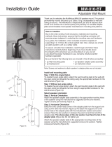
Step 1:
Disassemble the wall mount plate from the support arm by removing the 5/16”
hex bolt and pan locking washer (Figure 1).
Step 2: Mounting to a Wall:
Attach the mounting plate to the wall with the open center slot towards the
ceiling using the appropriate hardware for the application (Figure 1). If in
doubt, consult a local hardware specialist. Make sure the stop pin is placed into
the lower center hole of the wall plate (Figure 2).
Mounting to a ceiling Predetermine the desired direction of the speaker. Attach
the mounting plate to the ceiling structure with the open center slot towards the
speaker using the appropriate hardware for the application.
Figure 1

2004 ATG. Signal Hill, CA 90755 (562) 424-1100 0816-rev03
Step 3:
Lightly loosen the ¾” bolts securing the speaker adapter plate to the support
arm’s pivot rod. The support arm should be able to rotate easily without
binding. Attach the speaker adapter plate and support arm assembly to the
appropriate mounting holes of the speaker using the manufacturer’s
suggested screws and washers. The support arm should face the lower end
of the speaker. Tighten these fasteners permanently. If threaded inserts are
not included on the speaker, consult the speaker manufacturer for proper
mounting procedures. (Figure 3).
Step 4:
Lift the speaker and support arm up to the mounting plate and insert
the arm through the end of the mounting plate with the cross slot
(Figure 4). Line up the support arm’s threaded hole with the cross-slot.
Insert the 5/16” hex bolt with the pan locking washer through the
mounting plate’s slot and into the threaded hole of the support arm
(Figure 4). Be sure the pan locking washer is seated vertically outside
the slot.
Figure 2
Figure 3
Figure 4

2004 ATG. Signal Hill, CA 90755 (562) 424-1100 0816-rev03
Step 5: Setting the pan angle:
Rotate the speaker horizontally right or left until the speaker
is aimed in the desired direction. Permanently tighten the
hex bolt at the mounting plate (Figure 5).
Step 6: Setting the tilt angle
While supporting the speaker’s weight, lift the speaker up to
the desired tilt angle and hold it in position. Tighten the 3/4”
hex bolts at the sides of the speaker adapter plate, one is a
right hand thread and one is a left hand thread. Rotate the
left hand thread bolt on the grooved side of the pivot rod
counterclockwise to tighten. Rotate the other opposite bolt
clockwise to tighten. Be sure that the bolts have been
tightened permanently before releasing the weight of the
speaker (Figure 6).
If the tilt angle needs to be adjusted, DO
NOT PULL ON SPEAKER, rather loosen
the bolts then repeat step 6.
Step 7: Recommendation: Install Safety Cable
Attach a safety cable (sold separately) to the mounting
surface (Must be able to support at least five times the
weight of the speaker), then attach the other end of the
safety cable to the speaker. If no attachment is provided on
speaker, consult speaker manufacturer for advice on best
attachment point and method
Figure 5
Figure 6
/