Page is loading ...

2010 ATM Fly-Ware, Signal Hill, CA 90755 (562) 424-1100 Rev. 00 -050510
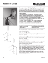
Figure 2
Figure 3
Step 3:
Carefully flip the two speakers together so that the top is facing up.
Removed the screws in the holes where the joiner plates are installed.
Install the joiner plates using the same holes as the bottom joiner plates
using the provided screw, split washer and flat washer (Figure 3).
Step 4:
Install the M10 x 35mm long eyebolts with flat washers on the outer front
holes of the side speaker (Figure 3).
Step 5:
Install the M10 x 35mm long eyebolt on the top rear of the speaker then
bridle to a single pull back cable (Figure 3). For dual pullback point
attach a pullback cable on each rear eyebolts.
Step 6:
When all joiner plates are installed, tighten screws permanently.
Step 7:
Attach a load rated suspension cables or chains on the top front
eyebolts. Use the rear eyebolts for pull back points and to adjust the tilt
angle of the loudspeaker cluster assembly as shown in the main
illustration (Figure 4).
Step 8:
Check all hardware connections before hoisting cluster.
Figure 4
Installation Guide
FP-EVH1152-2X1
ELECTRO-VOICE CLUSTER PACK PLANAR ARRAY KIT
The FP-EVH1152-2X1 planar array kit gives designers, contractors and audio
consultants the ability to create two EVH 1152 speakers in a tight pack or splayed
configurations. The FP-EVH1152-2x1 kit provides a method of flying a planar or
line array configuration while offering the capability of allowing cabinet’s splay angle
to be adjusted relative to each other to find the optimum sound directivity. A series
of holes are provided to easily adjust the splay or tilt angle from 20° to 60° at an
increment of 2.5° between speakers.
Contents:
Be sure that all of the following items are included in this kit before proceeding:
2pcs Joiner Plates
8pcs Button head screw, M10X45mm
8pcs Split lock washer, M10
8pcs Flat Washer, M10
4pc Eyebolt, M10x 35mm
Installing speakers must be performed by experienced professionals. If in doubt
about the integrity of the structure you are mounting or suspending to or not sure
about the proper hardware or method to use, consult a certified rigging company.
2010 ATM Fly-Ware, Signal Hill, CA 90755 (562) 424-1100 Rev. 00 -050510
Figure 1
Plates may differ per speaker model
FASPAC
TM
FP-EVH1152-2X1
2 WIDE X 1 DEEP PLANAR ARRAY CONFIGURATION
The FP-EVH1152-2X1 planar array kit gives
designers, contractors and audio consultants the
ability to create two EVH 1152 speakers in a tight
pack or splayed configurations. The FP-EVH1152-2x1
kit provides a method of flying a planar or line array
configuration while offering the capability of allowing
cabinet’s splay angle to be adjusted relative to each
other to find the optimum sound directivity. A series of
holes are provided to easily adjust the splay or tilt
angle from 20° to 60° at an increment of 2.5°
between speakers.
Installing speakers must be performed by
experienced professionals. If in doubt about the
integrity of the structure you are mounting or
suspending to or not sure about the proper hardware
or method to use, consult a certified rigging company.
Package contents:
2 pcs Joiner Plate
8 pcs Button head screw, M10x45mm long
8 pcs Split lock washer, M10
8 pcs Flat washer, M10
4 pcs Eyebolt, M10x 35mm long
1 pc Instruction Sheet
CAUTION: PLEASE READ CAREFULLY BEFORE PROCEEDING
Due to the wide variety of building structures, materials and
suspension methods, these instructions assume that the
installing contractor/installer will exercise good judgment in
selecting the proper mounting area and hardware. As a guide,
the installation, when complete, should be capable of supporting
at least 5 times the actual load. Follow building code
requirements to safely suspend the speakers to the building
structure
2 WIDE X 1 DEEP PLANAR ARRAY:
Step 1:
Flip the two speakers so that the bottoms are facing up and lay
them side by side. Unscrew existing speaker screws where the
joiner plate will be installed. Discard removed screws.
Step 2:
Decide the splay angles of the loudspeaker cluster (Figure 1). Install the joiner plate on the speakers using the appropriate holes for the desired
loudspeaker splay angles. Use the provided M10 screws, flat washers and split washers. Do not tighten bolts until all joiner plates are installed
(Figure 2).
Figure 1
Figure 2
Installation Procedure:
Step 1:Flip the two speakers so that the bottoms are facing up and lay
them side by side. Unscrew existing speaker screws where the joiner
plate will be installed. Discard removed screws.
Step 2: Decide the splay angles of the loudspeaker cluster (Figure 1).
Install the joiner plate on the speakers using the appropriate holes for
the desired loudspeaker splay angles. Use the provided M10 screws,
at washers and split washers. Do not tighten bolts until all joiner
plates are installed (Figure 2).
Step 3: Carefully ip the two speakers together so
that the top is facing up. Removed the screws in the
holes where the joiner plates are installed. Install
the joiner plates using the same holes as the bottom
joiner plates using the provided screw, split washer
and at washer (Figure 3).
Adaptive Technologies Group
1635 E. Burnett Street | Signal Hill, CA 90755 USA
Ph: 562.424.1100 | Fax: 562.424.3520
www.adapttechgroup.com
ALWAYS INSTALL SAFETY CABLES
WARNING: Mounting and/or suspension of audio and video equipment requires
experienced professionals. Improperly installed loudspeakers can result in property
damage, personal injury and/or liability to the installing contractor.

Step 4: Install the M10 x 35mm long eyebolts with at
washers on the outer front holes of the side speaker
(Figure 3).
Step 5: Install the M10 x 35mm long eyebolt on the
top rear of the speaker then bridle to a single pull
back cable (Figure 3). For dual pullback point attach
a pullback cable on each rear eyebolts.
Step 6: When all joiner plates are installed, tighten
screws permanently.
Step 7: Attach a load rated suspension cables
or chains on the top front eyebolts. Use the rear
eyebolts for pull back points and to adjust the tilt
angle of the loudspeaker cluster assembly as shown
in the main illustration (Figure 4).
Step 8: Check all hardware connections before
hoisting cluster.
Installation Guide
2010 ATM Fly-Ware, Signal Hill, CA 90755 (562) 424-1100 Rev. 00 -050510
Figure 2
Figure 3
Step 3:
Carefully flip the two speakers together so that the top is facing up.
Removed the screws in the holes where the joiner plates are installed.
Install the joiner plates using the same holes as the bottom joiner plates
using the provided screw, split washer and flat washer (Figure 3).
Step 4:
Install the M10 x 35mm long eyebolts with flat washers on the outer front
holes of the side speaker (Figure 3).
Step 5:
Install the M10 x 35mm long eyebolt on the top rear of the speaker then
bridle to a single pull back cable (Figure 3). For dual pullback point
attach a pullback cable on each rear eyebolts.
Step 6:
When all joiner plates are installed, tighten screws permanently.
Step 7:
Attach a load rated suspension cables or chains on the top front
eyebolts. Use the rear eyebolts for pull back points and to adjust the tilt
angle of the loudspeaker cluster assembly as shown in the main
illustration (Figure 4).
Step 8:
Check all hardware connections before hoisting cluster.
Figure 4
Figure 3
Figure 4
Adaptive Technologies Group
1635 E. Burnett Street | Signal Hill, CA 90755 USA
Ph: 562.424.1100 | Fax: 562.424.3520
www.adapttechgroup.com
ALWAYS INSTALL SAFETY CABLES
WARNING: Mounting and/or suspension of audio and video equipment requires
experienced professionals. Improperly installed loudspeakers can result in property
damage, personal injury and/or liability to the installing contractor.
FP-EVH1152-2X1
ELECTRO-VOICE CLUSTER PACK PLANAR ARRAY KIT

Installation Guide
Adaptive Technologies Group
1635 E. Burnett Street | Signal Hill, CA 90755 USA
Ph: 562.424.1100 | Fax: 562.424.3520
www.adapttechgroup.com
ALWAYS INSTALL SAFETY CABLES
WARNING: Mounting and/or suspension of audio and video equipment requires
experienced professionals. Improperly installed loudspeakers can result in property
damage, personal injury and/or liability to the installing contractor.
1 WIDE X 2 DEEP LINE ARRAY-
HORIZONTAL
Step 1-3 From 2 WIDE X 1 DEEP PLANAR ARRAY
Installation Instruction:
Step 4: Carefully ip the two speakers together so
that the top is facing up. Removed the screws in the
holes where the joiner plates are installed. Install
the joiner plates using the same holes as the bottom
joiner plates using the provided screw, split washer
and at washer.
Step 5 :Check all hardware connections before
hoisting cluster.
Step 6: For Line Array Conguration
Flip speakers so that the bottom is facing up. Arrange
speaker so that the EVF1181S is in between the
EVF1152S. Unscrew existing speaker screws and
discard (Figure 4).
Step 7: Determine the splay angle of the speakers
and the holes to use on the front joiner plate (Figure
2).
Step 8: Install the rear joiner plate on the two
middle rigging inserts of the EVF1181S subwoofer
using the provided screws and washers. Attach the
two EVF1152S side speakers with the EVF1181S
subwoofer using the lower slots of the rear joiner
plate with the provided screws and washers (Figure
4).
Step 9: Install the front joiner plate on the two front
rigging inserts of the EVF1181S subwoofer using the
provided screw and washer. Determine the holes
to use for the selected splay angle (Figure 2) then
secure the EVF1152S side speakers to the front
joiner plate using the provided screws and washers
(Figure 4). Do not tighten screws; leave it snug until
all plates are in position.
2010 ATM Fly-Ware, Signal Hill, CA 90755 (562) 424-1100 Rev. 00 -050510
FASPAC
TM
FP-EVH1152-2X1
1 WIDE X 2 DEEP LINE ARRAY CONFIGURATION
1 WIDE X 2 DEEP LINE ARRAY-
HORIZONTAL
Step 1-3 From 2 WIDE X 1 DEEP PLANAR
ARRAY Installation Instruction:
Step 4:
Carefully flip the two speakers together so that the
top is facing up. Removed the screws in the holes
where the joiner plates are installed. Install the
joiner plates using the same holes as the bottom
joiner plates using the provided screw, split washer
and flat washer.
Step 5:
When all plates are in position, tighten all screws
permanently
Step 6:
Remove and discard the screw on the side of the
designated upper speaker. Install the M10x 45mm
long eyebolts with flat washer on the side holes of
the designated upper loudspeaker (Figure 5).
Step 7:
Install the M10x 35mm long eyebolt on both the rear rigging holes of the
lowest speaker. Use these two eyebolts for connecting the pull back
cables (Figure 5).
Note:
Pull back can be individual cable per speaker or can be bridled to a
single point as shown in the 1 WIDE X 2 DEEP LINE ARRAY main
illustration.
Step 8:
Attach a load rated suspension cables or chains to the top eyebolts of the
upper loudspeaker. Use the eyebolt on the lowest speaker for pull back
points and to adjust the tilt angle of the loudspeaker speaker cluster
assembly as shown in the main illustration.
Step 9:
Check all hardware connections before hoisting cluster.
Figure 5
FP-EVH1152-2X1
ELECTRO-VOICE CLUSTER PACK PLANAR ARRAY KIT

Installation Guide
Note to installers:
Due to the wide variety of wall structures, materials and mounting methods, the installing contractor must exercise proper judgment in selecting
the mounting area and hardware.
As a guide, the installation, when complete should be capable of supporting 5 to 10 times the actual applied load. Always use a backup safety
system such as a safety cable.
To assure a trouble-free installation, read through and follow these instructions carefully before beginning. If you have doubts about the integrity of
the structure you are mounting to or you are not sure about the proper hardware to use, consult a structural and/or hardware specialist.
Caution: Due to the wide variety of structures, environments, materials and rigging methods, the installing contractor must exercise good
judgment in selecting the proper mounting area and hardware.
Adaptive Technologies Group
1635 E. Burnett Street | Signal Hill, CA 90755 USA
Ph: 562.424.1100 | Fax: 562.424.3520
www.adapttechgroup.com
ALWAYS INSTALL SAFETY CABLES
WARNING: Mounting and/or suspension of audio and video equipment requires
experienced professionals. Improperly installed loudspeakers can result in property
damage, personal injury and/or liability to the installing contractor.
Step 17: Figure 5 Install the two m10x 50mm long
eyebolt on the side rigging inserts of the selected
upper Figure 4 speakers Install the two m10x35 mm
long on the rear rigging inserts of the EVF1181S or
to the rear rigging insert of the bottom EVF1152S
(depending on the desired tilt angle) for pull back
points (Figure 5).
Step 18: Check all hardware connections before
hoisting cluster.
FP-EVH1152-2X1
ELECTRO-VOICE CLUSTER PACK PLANAR ARRAY KIT
/