Page is loading ...

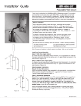
Installation Guide
WM-0-15-60
Speaker Wall Mount
The WM-0-15-60 wall mount is an excellent choice for various wall mounting positions as
well as 0° and 15° speaker tilt angles. The speaker are secured to standard loud speaker
mounting hole patterns, 5”x2.75” and 4” x 2.25” located on the rear of the speaker
cabinets. This mount secures to speakers by way of standard 4 hole mounting pattern
including 5” X 2 3/4 and 4 X 2 1/4 located on the rear panel of speaker cabinet.
Contents:
Be sure that all of the following items are included in this kit before proceeding:
1 pc wall mounting plate
1 pc speaker adapter assembly
1 pc hardware kit assembly
1 pc instruction sheet
Notes:
Screws and washer to attach wall mount assembly to wall are not included.
Screws and washer to attach speaker adapter to speaker are not included
Installation Procedure:
Step 1: The speaker tilt angle can be selected from either 0° or15°.
For 0° the wall mount tube is facing up, for 15° the wall mount tube is
facing down (Figure 1 and Figure 2)
Step 2: Secure the wall plate assembly to the wall
with the appropriate mounting hardware, hardware
not included (Figure 2).
Figure 1
Figure 2
Adaptive Technologies Group
1635 E. Burnett Street | Signal Hill, CA 90755 USA
Ph: 562.424.1100 | Fax: 562.424.3520
www.adapttechgroup.com
ALWAYS INSTALL SAFETY CABLES
WARNING: Mounting and/or suspension of audio and video equipment requires
experienced professionals. Improperly installed loudspeakers can result in property
damage, personal injury and/or liability to the installing contractor.

Step 3: Secure speaker to the speaker adapter plate
assembly with the opening of the channel facing up.
Align the speaker’s four mounting points with the
mount’s matching hole pattern. Use the speaker
manufacturer’s recommended fasteners; tighten
fasteners permanently through the mount and into the
speaker cabinet (Figure 3).
Step 4: Speaker arm assembly mounting options
range from 5.05” to 7.05” for 0° and 5.83” to 7.83” for
15° depending upon the hole used (Figure 4A and
4B).
Step 5: Attach the speaker adapter w/ speaker to
the wall mount assembly hole using 1/4-20 hex
head screw, nylon nut and at washer. Tighten
permanently. (Figure 5)
Step 6: Connect signal wire to the speaker terminals.
Step 7: Always Install Safety Cables
Install safety cable Attach a safety cable (sold
separately) to the mounting surface (must be able to
support at least ve times the weight of the speaker),
then attach the other end of the safety cable to the
speaker. If no attachment is provided on speaker,
consult speaker manufacturer for advice on best
attachment point and method.
Installation Guide
Note to installers:
Due to the wide variety of wall structures, materials and mounting methods, the installing contractor must exercise proper judgment in selecting
the mounting area and hardware.
As a guide, the installation, when complete should be capable of supporting 5 to 10 times the actual applied load. Always use a backup safety
system such as a safety cable.
To assure a trouble-free installation, read through and follow these instructions carefully before beginning. If you have doubts about the integrity of
the structure you are mounting to or you are not sure about the proper hardware to use, consult a structural and/or hardware specialist.
Caution: Due to the wide variety of structures, environments, materials and rigging methods, the installing contractor must exercise good
judgment in selecting the proper mounting area and hardware.
Figure 3
Figure 4A (0° Tilt)
Figure 4B (15 ° Tilt)
Figure 5
Adaptive Technologies Group
1635 E. Burnett Street | Signal Hill, CA 90755 USA
Ph: 562.424.1100 | Fax: 562.424.3520
www.adapttechgroup.com
ALWAYS INSTALL SAFETY CABLES
WARNING: Mounting and/or suspension of audio and video equipment requires
experienced professionals. Improperly installed loudspeakers can result in property
damage, personal injury and/or liability to the installing contractor.
PM-BAND-SERIES
PoleStar Pole Banding Kit 30” - 90”
/