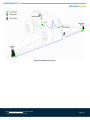
Norac Norac UC7 is a boom height control system that helps protect sprayers from damage, increases efficiency, and ensures accurate chemical application. Using ultrasonic sensors, it automatically adjusts the height of the sprayer boom to maintain a consistent distance from the ground, reducing the risk of collisions and minimizing chemical waste. The system is easy to install and can be used with a variety of sprayers, making it a versatile tool for farmers and agricultural professionals.
Norac Norac UC7 is a boom height control system that helps protect sprayers from damage, increases efficiency, and ensures accurate chemical application. Using ultrasonic sensors, it automatically adjusts the height of the sprayer boom to maintain a consistent distance from the ground, reducing the risk of collisions and minimizing chemical waste. The system is easy to install and can be used with a variety of sprayers, making it a versatile tool for farmers and agricultural professionals.


-
 1
1
-
 2
2
-
 3
3
-
 4
4
-
 5
5
-
 6
6
-
 7
7
-
 8
8
-
 9
9
-
 10
10
-
 11
11
-
 12
12
-
 13
13
-
 14
14
-
 15
15
-
 16
16
-
 17
17
-
 18
18
-
 19
19


Norac Norac UC7 Installation guide
- Type
- Installation guide
- This manual is also suitable for
Norac Norac UC7 is a boom height control system that helps protect sprayers from damage, increases efficiency, and ensures accurate chemical application. Using ultrasonic sensors, it automatically adjusts the height of the sprayer boom to maintain a consistent distance from the ground, reducing the risk of collisions and minimizing chemical waste. The system is easy to install and can be used with a variety of sprayers, making it a versatile tool for farmers and agricultural professionals.
Ask a question and I''ll find the answer in the document
Finding information in a document is now easier with AI
Related papers
-
Norac UC7-BC-CS05 Installation guide
-
-
-
-
-
-
-
-
-
Other documents
-
 temperzone UC7 Operating instructions
-
 temperzone UC7 User guide
-
Adamson S7P User manual
-
 Amazone X35 Operating instructions
-
 Hardi COMMANDER 7000 Instruction book
-
 versa ag leader User manual
-
 Ag Leader Integra Display User manual
-
Topcon A2677 User manual
-
GREAT PLAINS TSF1060 & TSF1260 Front Fold Boom Sprayer Operating instructions
-
Bestway Field Pro III 1600 User manual


