Page is loading ...

Instruction
Manual
DynoWare
Type 2825A…
2825A_002-195e-10.19

Instruction
Manual
DynoWare
Type 2825A…
2825A_002-195e-10.19


Foreword
Page 1 2825A_002-195e-10.19
Foreword
This manual is written for DynoWare, a general-purpose
data acquisition and analysis software.
Information in this document is subject to change without
notice. Kistler reserves the right to change or improve its
products and make changes in the content without
obligation to notify any person or organization of such
changes or improvements.
© 2002 … 2019 Kistler Group. Kistler Group products are
protected by various intellectual property rights. For more
details visit www.kistler.com. The Kistler Group includes
Kistler Holding AG and all its subsidiaries in Europe, Asia,
the Americas and Australia.
Kistler Group
Eulachstrasse 22
8408 Winterthur
Switzerland
Tel. +41 52 224 11 11
www.kistler.com

DynoWare Type 2825A…
Page 2 2825A_002-195e-10.19
Content
1.Introduction ................................................................................................................................... 6
1.1Getting software help ........................................................................................................... 7
1.2Customer support ................................................................................................................ 7
1.3Service and assistance .......................................................................................................... 8
1.4License agreement ............................................................................................................... 8
1.5Warranty .............................................................................................................................. 8
1.6Claims .................................................................................................................................. 9
2.Important information .................................................................................................................. 10
2.1For your safety ................................................................................................................... 10
2.2Warning ............................................................................................................................. 10
2.3How to use this manual ...................................................................................................... 10
3.Description of DynoWare ............................................................................................................ 11
3.1General .............................................................................................................................. 11
3.2System requirements .......................................................................................................... 11
4.Installation ................................................................................................................................... 13
4.1DynoWare
software installation .......................................................................................... 13
4.2HASP key installation ......................................................................................................... 14
4.2.1Type 5697A DAQ-System (USB2533) ................................................................... 14
4.2.2Charge amplifiers Type 5165A and Type 5167A ................................................... 15
4.3A/D card configuration for Type 5697A ............................................................................. 15
4.3.1Type 5697A DAQ-System (USB2533) ................................................................... 17
4.3.2Charge amplifiers Type 5165A and Type 5167A ................................................... 17
4.4Set card number to zero ..................................................................................................... 19
4.5Running DynoWare ........................................................................................................... 20
4.6Connecting the measurement signal cable ("Analog Input") .............................................. 20
4.6.1Type 5697A DAQ-System for DynoWare .............................................................. 20
4.6.2Charge amplifiers Type 5165A and Type 5167A ................................................... 21
4.7Connecting RS-232C interface cable for DAQ System 5697A ............................................ 21
4.7.1Connecting to PC / Notebook ............................................................................... 21
4.7.2Connecting to connecting box Type 5697A .......................................................... 22
4.7.3Charge amplifiers Type 5165A and Type 5167A ................................................... 23
4.8Using remote control interface on DAQ-systems................................................................ 23
4.9Important issues regarding Piezoelectric Dynamometers .................................................... 24
4.10Charge amplifiers ............................................................................................................... 24
5.Quick start ................................................................................................................................... 25
6.Reference ..................................................................................................................................... 29
6.1File... .................................................................................................................................. 29
6.1.1Open… ................................................................................................................. 29
6.1.2Save modified file .................................................................................................. 29
6.1.3Configuration... ..................................................................................................... 30
6.1.3.1Load… ................................................................................................... 30
6.1.3.2Save… ................................................................................................... 30
6.1.4Export… ................................................................................................................ 30

Introduction
2825A_002-195e-10.19 Page 3
6.1.5Print Graph ............................................................................................................ 32
6.1.6Print report ............................................................................................................. 33
6.1.7Print preview… ...................................................................................................... 33
6.1.8Print setup… .......................................................................................................... 36
6.1.9Copy to clipboard................................................................................................... 36
6.1.10Exit ......................................................................................................................... 36
6.2Acquisition .......................................................................................................................... 36
6.2.1Hardware… ........................................................................................................... 36
6.2.1.1Hardware selection ................................................................................ 37
6.2.1.2A/D board ............................................................................................. 37
6.2.1.2.1Configuration of LabAmp family - DAQ .......................................... 37
6.2.1.2.2Configuration of measurement computing DAQ ............................. 39
6.2.1.3Show hardware dialog between acquisition cycles ................................. 41
6.2.1.4Configuration of charge amplifiers for stationary Dynamometers .......... 41
6.2.1.4.1Configurations using LabAmp family – Amplifier Type 5167A ......... 42
6.2.1.4.2Configurations using Type 5011/5015 amplifiers ............................ 43
6.2.1.4.3Configurations using amplifier Type 5017/5019 .............................. 44
6.2.1.4.4Configurations using amplifier Type 5018 ....................................... 46
6.2.1.4.5Configurations using multichannel amplifier Type 5070 .................. 47
6.2.1.4.6Setup for multichannel charge amplifier Type 5080 ......................... 48
6.2.1.4.7Configurations using other amplifiers .............................................. 50
6.2.1.4.8Force & torque calculation of stationary dynamometers .................. 51
6.2.1.5Configuration of rotating cutting dynamometers ................................... 55
6.2.1.5.1Configurations using rotating cutting dynamometer Type 9123/9124
with signal conditioner Type 5223 ..................................................................... 55
6.2.1.5.2Configurations using rotating cutting dynamometer Type 9125 with
signal conditioner Type 5237 ............................................................................. 58
6.2.1.5.3Configurations using rotating cutting dynamometer Type 9170/9171
with signal conditioner Type 5238 ..................................................................... 59
6.2.2Edit… ..................................................................................................................... 60
6.2.2.1Parameter .............................................................................................. 61
6.2.2.2Physical channels ................................................................................... 63
6.2.2.3Calculated channels ............................................................................... 64
6.2.2.4Data manipulation ................................................................................. 65
6.2.3Start... .................................................................................................................... 66
6.3View... ................................................................................................................................ 68
6.3.1New… ................................................................................................................... 68
6.3.2Edit… ..................................................................................................................... 68
6.3.2.1Superimposition of views ....................................................................... 69
6.3.2.2Type of view .......................................................................................... 69
6.3.2.2.1y-t graph ......................................................................................... 69
6.3.2.2.2y-x graph ......................................................................................... 70
6.3.2.2.3Numerical graph .............................................................................. 70
6.3.2.2.4View of FTT based graphs ............................................................... 70
6.3.2.2.5Polar based graphs .......................................................................... 70
6.3.3Setup… .................................................................................................................. 71
6.3.4Documentation ...................................................................................................... 72
6.3.4.1Comments ............................................................................................. 72
6.3.4.2File, date, time ....................................................................................... 73
6.3.5Edit labels ............................................................................................................... 73
6.3.6Edit diagram colors ................................................................................................. 74
6.3.7Reset font to default .............................................................................................. 74
6.3.8Reset color to default ............................................................................................. 75
6.3.9Zoom ..................................................................................................................... 75
6.3.9.1Manual scaling....................................................................................... 75
6.3.9.2Graphical zoom...................................................................................... 76

DynoWare Type 2825A…
Page 4 2825A_002-195e-10.19
6.3.10Zoom out .............................................................................................................. 76
6.3.11Lock scaling ........................................................................................................... 76
6.3.12Unlock scaling ....................................................................................................... 76
6.3.13Horiz. grid ............................................................................................................. 76
6.3.14Vert. grid ............................................................................................................... 76
6.3.15Toolbar .................................................................................................................. 76
6.3.16Status bar .............................................................................................................. 77
6.4Analysis... ........................................................................................................................... 78
6.4.1Statistics ................................................................................................................ 78
6.4.2Cursor tool ............................................................................................................ 79
6.4.3Partial FFT tool ...................................................................................................... 80
6.4.4Signal drift compensation ...................................................................................... 81
6.4.5Smoothing on… .................................................................................................... 83
6.4.5.1Moving mean ........................................................................................ 83
6.4.5.2Moving median ...................................................................................... 84
6.4.6Smoothing off ....................................................................................................... 86
6.4.7Filtering on… ........................................................................................................ 86
6.4.7.1Filtered signalLow Pass........................................................................... 87
6.4.7.2High pass ............................................................................................... 87
6.4.7.3Band pass ............................................................................................... 88
6.4.7.4Band stop ............................................................................................... 88
6.4.7.5Filter setup ............................................................................................. 88
6.4.7.5.1Edge frequencies .............................................................................. 88
6.4.7.5.2Filter order ....................................................................................... 88
6.4.8Filtering off ............................................................................................................ 88
6.4.9Data manipulation offline… .................................................................................. 88
6.4.9.1Apply to all cycles in file ......................................................................... 89
6.5Tools... ............................................................................................................................... 90
6.5.1Voltmeter… .......................................................................................................... 90
6.5.2Oscilloscope… ....................................................................................................... 90
6.6Options... ........................................................................................................................... 91
6.6.1User mode ............................................................................................................. 91
6.6.1.1Supervisor .............................................................................................. 92
6.6.1.2Operator ................................................................................................ 92
6.6.1.3Change Password .................................................................................. 92
6.6.2Additional channels ............................................................................................... 92
6.6.3FFT axis settings .................................................................................................... 93
6.7Window... .......................................................................................................................... 93
6.7.1Cascade ................................................................................................................. 93
6.7.2Tile horizontal ........................................................................................................ 93
6.7.3Tile vertical ............................................................................................................ 94
6.7.4Arrange icons ........................................................................................................ 94
6.7.5Close all ................................................................................................................. 94
6.7.6<open windows list> ............................................................................................. 94
6.8Help... ................................................................................................................................ 94
6.8.1Help topics ............................................................................................................ 94
6.8.2Select language ..................................................................................................... 94
6.8.3About DynoWare .................................................................................................. 94
7.Appendix ...................................................................................................................................... 95
7.1Graphs ............................................................................................................................... 95
7.2Language selection ............................................................................................................. 96
7.3Shortcut key summary ........................................................................................................ 96
7.4Modifying the report logo .................................................................................................. 96
7.5Example files ...................................................................................................................... 97

Introduction
2825A_002-195e-10.19 Page 5
8.Technical data of DAQ-systems ................................................................................................... 98
8.1DAQ system Type 5697A ................................................................................................... 98
8.1.1General data .......................................................................................................... 98
8.1.2Power supply ......................................................................................................... 98
8.1.3A/D conversion ...................................................................................................... 98
8.1.4Connections ........................................................................................................... 99
8.1.5Remote control ...................................................................................................... 99
8.2DAQ system of LabAmp Type 5167A ................................................................................. 99
8.2.1General data .......................................................................................................... 99
8.2.2Power supply ......................................................................................................... 99
8.2.3A/D conversion ...................................................................................................... 99
8.2.4Connections ......................................................................................................... 100
8.2.5Remote control .................................................................................................... 100
9.Measuring chain used ................................................................................................................. 101
9.1DAQ system Type 5697A ................................................................................................. 101
9.2DAQ system of LabAmp Type 5167A ............................................................................... 102
10.Index ........................................................................................................................................... 103
Total pages 104

DynoWare Type 2825A…
Page 6 2825A_002-195e-10.19
1. Introduction
We thank you for choosing a Kistler quality product. Please
take the time to thoroughly read this instruction manual. It
will help you with the installation, maintenance, and use of
the DynoWare system.
To the extent permitted by law Kistler does not accept any
liability if this instruction manual is not followed or
products other than those listed under Accessories are
used.
DynoWare
is an easy-to-use data acquisition and
manipulation program. The typical Windows controls apply
to the graphs and dialog boxes in DynoWare. This section
will give you a quick overview of the capabilities of
DynoWare.
The menu bar is your access to all areas of DynoWare. It is
divided into sections covering specific functions such as file
handling, data acquisition configuration, hardware
configuration, data viewing, window control, and
obtaining help. In addition to the menu bar, there is a
toolbar similar to those found in word processing and
spreadsheet programs. The toolbar consists of icons that
execute a specific function when clicked.
The user has full control over data acquisition. Sampling
rate and length of trials, as well as amplifier range and
trigger options are all easily accessible. The units of data
acquisition can be customized to the desired physical data
being measured.
The graphs are designed to be easy to read, and can be
fully customized. The number of graphs to view is flexible,
along with default parameters so each trial is readily
viewed in a format that is most useful to the user.
If you have questions at any time while in DynoWare,
simply press the F1 key and the DynoWare onine help
window appears. Help is also available from the menu bar.
Kistler offers a wide range of products for use in measuring
technology:
Quartz crystal sensors for force, torque, strain, pressure,
acceleration, shock, vibration and acoustic-emission
Piezoresistive pressure sensors and transmitters
Signal conditioners, indicators and calibrators
Electronic control and monitoring systems as well as
application-specific software for measuring technology
Kistler also develops and produces measuring solutions for
the application field engines, vehicles, manufacturing,
plastics and biomechanics.

Introduction
2825A_002-195e-10.19 Page 7
Our product and application brochures will provide you
with an overview of our product range. Detailed data
sheets are available for most products.
1.1 Getting software help
DynoWare software takes advantage of an online help
system to offer you quick assistance.
To receive immediate help from wherever you are in
DynoWare, press the F1 key and a window will pop up
with specific advice about where you currently are in the
software.
Help is also accessible through the menu bar found at the
top of the screen.
If you need additional help beyond what can be found
either on-line or in this manual, please contact Kistler's
extensive support organization.
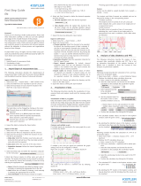
Fig. 1: Help is available by pressing the F1 key or by
selecting the Help from the menu
1.2 Customer support
The worldwide Kistler service organization is available for
any special questions or problems that you may have after
your careful study of these instructions.
Note, refer to sections 1.3 through 1.6 for general policies
on customer support. Before you call, please be ready to
fully explain your problem. If you are experiencing a
problem with DynoWare
software, please try to duplicate
the problem and take a snapshot of the screen by pressing

DynoWare Type 2825A…
Page 8 2825A_002-195e-10.19
the "print screen" button. This copies the screen to the
clipboard so that it can be pasted into a word processing
program and printed. You can e mail this picture to Kistler.
1.3 Service and assistance
The customer is responsible for proper DynoWare
installation and operation. DynoWare
must be installed as
per instructions provided in sections 4 and 5. If
modifications to these instructions are necessary for a
particular purchaser site, Kistler recommends the purchaser
contact a Kistler representative for input and advice
regarding these changes.
Installation problems and subsequent system performance
difficulties can be adverted by timely communication.
Often, questions can be answered through email or
telephone conversations. The purchaser is encouraged to
email or call the appropriate Kistler organization in the
event of such questions.
We welcome comments and suggestions for future
features and enhancements.
1.4 License agreement
Please refer to the Software License Agreement packet
containing your DynoWare software and to the license
presented during installation. This packet thoroughly
details the Software License Agreement.
You may permanently transfer the software to another
user provided you notify Kistler in advance, transfer the
documentation and all disks, and notify the new user of
the terms and conditions of the license agreement.
1.5 Warranty
Kistler warrants DynoWare to be free from defects in
material and workmanship as stated in the software license
agreement. It is warranted only under normal use and
service. The period of warranty is twelve (12) months from
date of shipment.
When returning items under warranty, said equipment
shall be returned to Kistler Instruments prepaid. Full details
relative to the claim or malfunction shall accompany the
shipment. No action will be taken until these details are
received. Please contact Kistler or your Kistler

Introduction
2825A_002-195e-10.19 Page 9
representative for a Return Authorization Number before
returning goods.
Settlement will be made at Kistler’s discretion, either
through repair or replacement of the item in question or
through issuance of full credit. Damage occurring through
misuse or mishandling, will not be covered by this
warranty.
This warranty is in lieu of all warranties expressed or
implied, and of all obligations or liabilities on the part of
Kistler Instruments for damages following the use or
misuse of items supplied. Any unauthorized disassembly or
attempt at repair shall void this warranty.
No agent or representative is authorized to assume for the
Corporation any liability except as set forth within this
warranty document.
1.6 Claims
Claims relating to goods delivered must be made within 14
days of receipt of goods. After fault determination by
Kistler, settlement will be made either by the carrier,
insurer, or Kistler. Means will be through replacement,
repair or credit

DynoWare Type 2825A…
Page 10 2825A_002-195e-10.19
2. Important information
Please practice common sense safety rules at all times.
2.1 For your safety
Prior to any installation and repair work or cable changes,
you must disconnect all power sources from the
instruments.
Observe all local safety regulations concerning the
handling of line-powered electrical and electronic
equipment.
When it must be assumed that safe operation is no longer
possible, the computer, charge amplifier, etc. must be taken out
of operation and secured against unintentional use.
Whenever opening covers or removing parts, except where
this can be done by hand, use caution where parts under
hazardous voltage are exposed.
2.2 Warning
Any breakage of the ground conductor inside or outside
the instruments, or loosening of the ground conductor
connection may render the instrument dangerous.
The power plug must be inserted in to a socket with a
ground connector. The protection must not be nullified by
an extension line lacking a protective ground connector.
When changing the signal conditioner fuses, only the
standard type with the specified amperage rating must be
used. Use of repaired fuses or short-circuiting the fuse
holder is expressly forbidden.
2.3 How to use this manual
This manual will take you through the installation and
setup of the DynoWare software, and a complete
reference to all of the features of this software.
If you are eager to begin operation of DynoWare we
recommend section 5 of this manual for a quick start
guide. Remember that on-line help is always available by
pressing the F1 key from anywhere in the software.

Description of DynoWare
2825A_002-195e-10.19 Page 11
3. Description of DynoWare
3.1 General
DynoWare is a general-purpose data acquisition and
display software package suitable for cutting force and
general sensor / dynamometer applications. DynoWare lets
you quickly setup, record, and display reaction forces and
torques. Although although the software was developed
specifically for the measurement of cutting forces in
mechanical machining processes, the measurement data
acquisition and analysis functions can also be used for
other measurement tasks. Depending on the data
acquisition card, up to 16 channels are available for
measurement acquisition. The DynoWare software
supports data acquisition cards for the PCI bus, PC cards
for notebooks, the USB data acquisition system 5697A and
the Ethernet based charge amplifiers 5165A and 5167A
with DAQ functionality
.
Fig. 2: The DynoWare splash screen appears for
a few seconds when the application starts
3.2 System requirements
Recommended Computer Specifications:
Windows 7 (32 bit and 64 bit versions), Windows 8
and Windows 10
Pentium PC, 1 GHz or higher
At least 512 MB of RAM

DynoWare Type 2825A…
Page 12 2825A_002-195e-10.19
Graphics card with at least 800x600 pixels and 256
colors
At least 100 MB of free hard-disk space
One USB 2.0 port for DAQ-System Type 5697A
or
One Ethernet port 2xRJ45 for DAQ-System Type 5167A
Adobe Reader for printing out measurement data
Color printer (recommended)
Windows
is a registered trade mark of Microsoft
Corporation.
Adobe
Acrobat
Reader
is a registered trade mark of
Adobe.

Installation
2825A_002-195e-10.19 Page 13
4. Installation
This chapter will show you how to install the data
acquisition card, the DynoWare
software, and how to
configure the data acquisition hardware, as well as connect
the cable from the A/D card to the signal conditioner.
4.1 DynoWare software installation
The DynoWare software can be downloaded from the
Kistler website under Type No. 2825A.
Some antivirus software packages can adversely affect
the DynoWare installation process. Temporarily disable
your antivirus software prior to installation.
To install DynoWare proceed as follows:
1. unpack the downloaded zip file
2. click on the "kistlersetup.exe" application
3. select "continue with installation".
4. for the installation select "Install DynoWare
Software".
5. follow the instructions
The first installation screen will present you with a choice
of the default language.
You can switch the user language of DynoWare at any
stage of operation.
Then you will be presented the License Agreement.
Confirming acceptance displays the readme and user
information, and the destination folder for programs and
data can be specified. The Setup Type dialog allows you to
choose between Complete and Custom installation.
Normally, Setup Type should be set to "Complete"
"Complete" installs all components, such as the DynoWare
application, the HASP driver, the drivers of the data
acquisition system as well as the drivers of the USB
interfaces at the connection box Type 5697A and the
installation wizard for the LabAmp Type 5167A/5165A.
"Custom" installs only one specific component.

DynoWare Type 2825A…
Page 14 2825A_002-195e-10.19
We always recommend to install the "complete"
version of this software with all drivers.
Pressing "Install" starts the actual installation. Follow the
instructions. Finally, to apply the drivers the PC must be
restarted.
4.2 HASP key installation
Without a hardware key or "dongle" DynoWare only
starts in the demonstration mode.
The dongle (HASP key, runtime license) is needed to
acquire data and exploit the various possibilities offered by
DynoWare. This dongle is the only way of legitimizing the
software.
Install the runtime license as follows:
1. After installing DynoWare insert the dongle in a free
USB port on your computer.
The relevant drivers are installed automatically.
4.2.1 Type 5697A DAQ-System (USB2533)
The following procedure is recommended for installing the
A/D card:
Make sure to take note of the technical information in
the file K20.302-11e Type 5697 DAQ.pdf in the
DynoWare installation folder (Documents/Technical
Notes) before inserting this card.
If you are using the DAQ-System Type 5697A you can
go straight to section 4.3.3.

Installation
2825A_002-195e-10.19 Page 15
1. Ensure DynoWare is completely installed (see section
4.1).
2. Power up the data acquisition system with the switch
in the OFF position. The outer ring of the connector
must be tightened clockwise beforehand.
3. Connect the acquisition system to the PC with the
included USB cable.
4. Insert the USB runtime license dongle (HASP key) into
the matching slot in the data acquisition system.
5. Switch the data acquisition system for DynoWare on
(ON position) after starting the Windows operating
system.
6. Windows detects the device and installs its drivers. If
Windows is searching for drivers, search in the
DynoWare installation folder then follow the instruc-
tions.
7. Windows loads the required drivers and configures
them for the Data Acquisition System Type 5697A.
8. Follow the instructions in section 4.3.1.
Older cards can be activated manually. Whenever the
DAQ-System Type 5697A is removed from the
computer and reconnected, or switched off and on
again, INSTACAL must be started to allow loading of the
necessary drivers.
4.2.2 Charge amplifiers Type 5165A and Type 5167A
The following procedure is recommended for installing the
charge amplifiers Type 5165A and Type 5167A:
1. Ensure DynoWare is completely installed (see section
4.1).
2. Power up the 5165A/5167A system with the switch in
the OFF position by connecting the power supply.
3. Connect the measuring amplifier (Ethernet Sync in or
Sync out) via a network cable directly to a computer or
a network (e.g network switch).
4. Switch the 5165A/5167A on (ON position) after
starting the Windows operating system.
5. No driver installation is required.
6. Follow the instructions in section 4.3.2.
4.3 A/D card configuration for Type 5697A
The software configuration process involves two steps. In
the first the card and data acquisition drivers are
configured with INSTACAL. This requires certain routines
from the manufacturer of the acquisition card. In a second
step this setup must be exported to DynoWare.

DynoWare Type 2825A…
Page 16 2825A_002-195e-10.19
INSTACAL can be started under the Measurement
Computing group of programs. The program configures
the driver and A/D card setup for you. Look for the
Measurement Computing group of programs (Start menu
(All) Programs) and choose the Instacal icon.
Fig. 3: Instacal board configuration program
The Instacal card configuration program will
automatically identify and plug-and-play capable data
acquisition cards. Manually add any non plug-and-play
cards.
Selecting the Instacal program Calibrate menu option
will reconfigure the card's factory calibrated parameters
and affect the accuracy of your measurements. Do Not
run the Calibration routine.
Instacal will automatically identify any installed plug-and-
play cards. Any non plug-and-play card will have to be
manually added by selecting the Install menu option and
then selecting the desired card from the list. Instacal should
be run any time a card is removed from a computer (even
for PCMCIA cards).
Fig. 4: Configuration for the PCIM-DAS1602/16

Installation
2825A_002-195e-10.19 Page 17
DynoWare will use the card configured in Instacal as
board zero. By default, the "DEMO-BOARD" is installed
as board zero. Remove the "DEMO-BOARD" and
reconfigure the desired card to be number zero (See
section 4.4). This applies to all of the A/D cards listed
here.
Once the card is installed it will need to be configured.
Right click on the card and select Configure… or double
click the card.
4.3.1 Type 5697A DAQ-System (USB2533)
See technical information K20.302-11e Type 5697
DAQ.pdf in DynoWare installation folder for more detailed
information.
The following values must be set:
Channels Choose 64 channels, single-ended mode (note: Instacal
automatically controls the hardware setup).
If the card is not set to 64 channels single-ended, the
following message is displayed when DynoWare is started
up:
Fig. 5: Message of changed channel configuration
DynoWare automatically switches to 64 channels single-
ended.
4.3.2 Charge amplifiers Type 5165A and Type 5167A
The following approach is recommended to establish a
connection with the measuring amplifier via Ethernet.
1. Find the Device in the Network
a.) Start the "SetupWizard" tool that finds all Kistler
network devices (tool can be found under
www.kistler.com in the download area of the
Kistler LabAmp Type 5165A/5167A).
/