Page is loading ...

Quick Start Installation
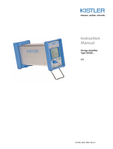
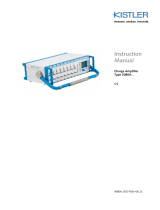
Piezoresistive Amplifier with PiezoSmart®
Type 4624AK...
4624AK_002-657e-07.16
Contents, front page
1. General Information
2. Scope of Delivery and Accessories
3. Measuring Chain Overview
4. Device Description
5. Voltage Supply and Signal Outputs
6. Connecting Sensors
Contents, back page
7. Explanation of the LEDs
8. Adjusting the Zero Point with Pushbuttons
9. Amplifier Parameterization via Web Interface
10. Installation of the Amplifier
11. Restoring all Settings
12. Repairs at Kistler
13. Disposal Instructions for Electronic Devices
1. General Information
The amplifier Type 4624AK... is a measuring amplifier for
piezoresistive pressure sensors for universal application. As
a result of its automatic sensor identification (PiezoSmart®),
the amplifier can be adapted to the connected pressure sen-
sor within a very short amount of time. This results in high
flexibility and process reliability in day-to-day applications.
The present instructions are for rapid commissioning of the
amplifier. Additional technical information can be found in
the data sheet (Doc. No. 003-105). For explanations regard-
ing optional parameterization via the web interface, please
refer directly to the Online Help function.
2. Scope of Delivery and Accessories
Included in the scope of delivery (contents of packaging) are:
• Amplifier Type 4624A
• Installation plate
Connecting cables for signal output and network connection
are available as optional accessories (see data sheet Type
4624AK..., Doc. No. 003-105).
3. Measuring Chain Overview
The amplifier is equipped with the Kistler PiezoSmart® sensor
identification feature. This enables the characteristic values of
the sensor to be read out automatically by an electronic data
sheet (TEDS) integrated in the sensor. Various measurement
chains and compatibilities are displayed below.
Foreword
Thank you for choosing a Kistler quality product. Please read
these instructions carefully, so that you can take optimum
advantage of the versatile features of this product.
The information in this document is subject to change at any
time without prior notice. Kistler reserves the right to improve
and alter this product in the interests of technical advance-
ment without being under obligation to notify any individuals
or organizations of such modifications.
©2013 ... 2016, Kistler Group. All rights reserved.
5. Voltage Supply and Signal Outputs
Voltage supply and analog signal outputs for pressure and
temperature are accomplished through the 8 pin socket with
M12x1 locking mechanism (A). The connection can be made
in various ways:
• Standard industrial cable (8 pin, M12x1)
e.g. Kistler Type 4777A5 (5m)
• Connecting cable with BNC signal outputs for pressure
and temperature Kistler Type 1200A179A3 (3m)
• Adapter cable for the connection to a Binder plug in the
case of previous utilization of an amplifier of Type 4618
Kistler Type 4775A0,5 (0,5m)
In the event that a standard industrial cable is used, supply
and signal reception are to be executed in accordance with
the following pin assignment.
Note on voltage supply and GND wiring:
• Voltage supply must range between 10 ... 30 VDC.
Values above 30 VDC could damage the device.
Values below 10 VDC could lead to malfunctions.
• Supply GND (-) must not be connected with Signal
GND (-) of analog signal output.
6. Connecting Sensors
More recent sensor generations permit the direct connection
of the sensors (DS Types) to the amplifier. Older sensors can
be connected using a connecting cable ( Chap. 3).
When using Kistler sensors and adapter cables, the connector
configuration is standardized and need not be checked. The
following section can be skipped.
Connecting sensors from other manufacturers:
When using sensors from other manufacturers, the connec-
tion must be accomplished in accordance with the following
testing bridge definition:
Instructions when using sensors from other manu-
facturers:
• The sensor testing bridge is supplied by the amplifier
with 1 mA constant current. This requires recalcula-
tions of sensitivity and the sensor zero point (ZMO)
under certain circumstances
• In order to avoid temperature errors, the sensor
must be equipped with analog temperature com-
pensation
Sensors Cable Remark
40xx…DS – Plug & Play
Output signal for pressure and
temperature
4007B…S
4049A…S
4065A…S
4067C…S
4761B Plug & Play
Output signal for pressure and
temperature
4005BA…V200S
4045A…V200S
4075A…V200S
4763B TEDS version not supported.
Manual parameterization via
web interface required
Chap. 9
Output signal for pressure
4045A 4761B Manual parameterization via
web interface Kap. 9
Output signal for pressure
4075A 4763B
Sensors from
other
manufactures
1. Testing for correct connection
and supply Chap. 6
2. Manual parameterization via
web interface Chap. 9
Output signal for pressure
Property Chapter
AVoltage supply and signal outputs via
8 pin, M12x1 socket Chap. 5
BSensor connection via 5 pin Fischer socket
(103 A054) Chap. 6
CLEDs indicating amplifier status and settings Chap. 7
DPushbuttons for setting the sensor zero point Chap. 8
EAmplifier parameterization via ethernet
connection (RJ45 socket) Chap. 9
FInstallation plate for amplifier installation Chap. 10
8 pin socket
M12x1
# Description Cable Color
Type 4777A5
1 Supply GND brown
2 Signal GND white
3 Do not connect –
4 Pressure output signal blue
5 Temperatur output signal black
6 Do not connect –
7 Do not connect –
8 Supply (10 … 30 VDC) gray
A
5 pin Fischer
Socket
# Description Testing Bridge
1 Bridge supply (+IN)
2 Bridge supply (-IN)
3 Bridge supply (-IN)
4 Bridge signal (-Out)
5 Bridge signa (+Out)
B
4. Device Description
The following brief description explains the basic functions
and makes reference to the corresponding chapters.
Fischer 5-pol Plug
male
Fischer 5-pol Connector
female
Fischer 4-pol
Conn., female
Type 4777A5
No TEDS
TEDS 3/4
supported
TEDS 2 not
supported
TEDS 3/4
supported
1
2
3
Fischer 4-pol
Conn., female
4
No TEDS
5
Plug & Play
Plug & Play
Manual Parametriziation
Manual Parametriziation
Manual Parametriziation
Type 4763B…
Type 4763B…
Type 4761B…
Type 4761B…
(Type 4065/4067 not yet supported)
(Type 4065/4067 not yet supported)

Kistler Group
Eulachstrasse 22
8408 Winterthur, Switzerland
Tel. +41 52 224 11 11
Fax +41 52 224 14 14
info@kistler.com www.kistler.com
4624AK_002-657e-07.16 ©2013 ... 2016, Kistler Group
Sections 7 and 8 refer to the displays and operating
elements on the front panel of the amplifier:
7. Explanation of the LEDs
The 5 LEDs on the amplifier indicate the operating status of
the amplifier.
8. Adjusting the Zero Point with Pushbuttons
The zero point of the sensor can be adjusted using the push-
buttons located on the front panel or via the web interface.
In order to obtain as precise a measurement as possible, the
zero point must be corrected at regular intervals. The main
reasons for the shifting of the zero point are:
• Zero point shifting caused by installation of the sensor
(tightening torque)
• Change in surrounding temperature conditions of the sensor
• Aging of the sensor
Procedure for using pushbuttons to make adjustments:
Resetting the zero point:
The zero balance can be reset via the pushbuttons. To accom-
plish this, proceed as follows:
1. Briefly press the 'Offset Adjust' button once
The Uout or Iout LED flashes green (setting mode)
2. Press both arrow buttons simultaneously for at least 1
second
The zero point is reset
3. Press the 'Offset Adjust' button once more
The Uout or Iout LED stops flashing
9. Amplifier Parameterization via Web Interface
Amplifier parameterization via web interface is mandatory in
the case of sensors either without or with an old version of
PiezoSmart® Standard ( Chap. 3, Measuring Chain Over-
view). Nevertheless, additional settings can be made for all
sensors or additional features can be used:
• Conversion of the signal outputs (voltage to current out-
put)
• User-defined amplifier settings
• Information regarding a connected PiezoSmart® sensor
• Digital display of pressure and temperature
• Simplified zero-point setting
• Digitally adjustable low-pass filter
• Firmware update
• Gain adjustment of measuring chain
• Lock sensor to amplifier (measuring chain)
Establishing a connection to the amplifier:
Here the procedure of a direct connection of a single amplifi-
er with a computer is shown (for other connection types, see
video tutorials on www.kistler.com). To this end, the com-
puter’s IP address must be adjusted. We recommend the
following procedure:
1. Ensure that the amplifier is working at the default factory
settings, respectively, a static IP of 192.168.1.100 is set
(Restoring all settings Chap. 11)
2. Switch off all network connections (e.g. WLAN), which
are not connected to the amplifier
3. Connect the amplifier (connection E) with a computer
using a network cable (e.g. Kistler Type 1200A49A1)
4. Change the IP address of the computer:
a) Start Control Panel Network and Internet
Open Network and Sharing Center
b) Open the menu “Change adapter settings”
c) Open properties of the LAN connection
d) Open properties of the internet protocol v4
e) Use the static IP address 192.168.1.101 and subnet
mask 255.255.255.0:
10. Installation of the Amplifier
The amplifier can be screwed onto a fixed surface with the
installation plate supplied.
11. Restoring all Settings
The factory default settings of the amplifier can be restored
using the operating buttons on the front panel. This will
cause all user and network settings to be reset. To accomplish
this, proceed as follows:
1. Switch off the device (disconnect power supply)
2. Switch on the device while at the same time pressing the
'up' arrow button for 10 seconds
3. The status LED (1) is illuminated in red and flashes red 3
times when the reset has been successful.
12. Repairs at Kistler
Repairs at the Kistler factory can be arranged via the local
sales company.
Information can be found under www.kistler.com
13. Disposal Instructions for Electronic Devices
Old electronics devices may not be dis-
posed of with household refuse/residu-
al waste. Please return disused devices
to the nearest electronics disposal office
for disposal or contact your Kistler Sales
Representative.
Status
LED
The Status LED indicates the operating status of the
entire measuring chain (amplifier and sensor)
LED Status Operating Status
Illuminated in
green
Amplifier is ready for operating
Flashing in
green
Setting are being adopted
• during settings in the web
interface
Illuminated in
orange
Amplifier is not ready for operation
• while amplifier is starting
• if no sensor is connected
Illuminated in
red
An error has occurred, possible
measures:
• Check whether parameters are in a
valid range (in the web interface)
• Resetting all settings ( Kap. 11)
1
TEDS
LED
The TEDS LED shows whether a functionally
PiezoSmart® sensor is connected
LED Status Operating Status
Illuminated in
blue
Supported and functional Kistler
PiezoSmart® sensor connected
3x flashing in
blue
Reading TEDS data of sensor loaded
into amplifier
Flashing in blue Amplifier in Measuring Chain
Lock Mode but wrong sensor
connected
LED off No PiezoSmart® sensor connected,
TEDS defective or sensor not compa-
tible
• Check measuring chain ( Chap. 3)
2
Ethernet
LED
The ethernet LED indicates the status of data
transmission via ethernet
LED Status Operating Status
Illuminated
in orange
Network connection available
Flashing in
orange
Data transmission
LED off No network connection available
3
Power/
Output
LEDs
The power/output LEDs indicate whether the
amplifier outputs the analog pressure signal in voltage
or current
LED Status Operating Status
Uout
illuminated
in green
Analog pressure signal in voltage
(0 … 10 V)
lout
illuminated
in green
Analog pressure signal in current
(4 … 20 mA)
Uout/lout
flashing in
green
During zero balance
( Chap. 8)
4
1Make measuring chain ready for operation ( Chap.
5+6), so that an analog pressure signal is output
2Have pressure signal displayed via display device (e.g.
voltmeter) and compare with reference value (e.g. baro-
metric pressure)
3
Press once
Uout/lout
LED
Briefly press the "Offset Adjust"
button once
The Uout oder Iout LED flashes
green (setting mode)
4Use arrow buttons to set sensor zero
point
Press briefly:
Increment approx. 1 mV (0,01 %FS)
Prolonged pressing:
Increment approx. 10 mV (0,1 %FS)
5Compare continuously with reference value
6
Press once
Uout/loud
LED
Press the "Offset Adjust" button once
more
The Uout or Iout-LED stops flashing
Note:
If no setting is made whithin 10
seconds after the first time the "Offset
Adjust" button is pressed (Step 3),
then the setting mode will be ended
automatically
5. Confirm with OK. A connection to the amplifier is now
established
6. Enter the IP address of the amplifier (192.168.1.100) in
the address bar of the browser
Switching amplifier to DHCP-mode:
The amplifier can be switched to DHCP-mode (Dynamic Host
Configuration Protocol). This may be useful in case of an
amplifier integration into a company's network. The DHCP-
mode can be set by using the push buttons at the front panel:
1. Switch off the device (disconnect power supply)
2. Switch on the device while at the same time pressing the
‘down’ arrow button for 10 seconds
3. The status LED (1) is illuminated in red and flashes red 3
times when the change was successful.
/