Page is loading ...

ILD 1420-10
ILD 1420-25
ILD 1420-50
ILD 1420-100
ILD 1420-200
ILD 1420-500 ILD 1420-10CL1
ILD 1420-25CL1
ILD 1420-50CL1
Operating Instructions
optoNCDT 1420

MICRO-EPSILON
MESSTECHNIK
GmbH & Co. KG
Koenigbacher Str. 15
94496 Ortenburg/Germany
Tel. +49 (0) 8542/168-0
Fax +49 (0) 8542/168-90
e-mail [email protected]
www.micro-epsilon.com
Intelligent laser optical displacement measurement

optoNCDT 1420
Contents
1. Safety ........................................................................................................................................ 9
1.1 Symbols Used ................................................................................................................................................. 9
1.2 Warnings .......................................................................................................................................................... 9
1.3 Notes on CE Marking .................................................................................................................................... 10
1.4 Intended Use ................................................................................................................................................. 11
1.5 Proper Environment ....................................................................................................................................... 11
2. Laser Safety ............................................................................................................................ 12
2.1 ILD1420 .......................................................................................................................................................... 12
2.2 ILD1420 CL1 .................................................................................................................................................. 14
3. Functional Principle, Technical Data ..................................................................................... 15
3.1 Short Description ........................................................................................................................................... 15
3.2 Auto Target Compensation (ATC) ................................................................................................................. 16
3.3 Technical Data ILD1420 ................................................................................................................................. 17
3.5 Technical Data ILD1420-CL1 ......................................................................................................................... 19
4. Delivery ................................................................................................................................... 21
4.1 Unpacking, Included in Delivery.................................................................................................................... 21
4.2 Storage .......................................................................................................................................................... 21
5. Installation .............................................................................................................................. 22
5.1 Notes for Operation ....................................................................................................................................... 22
5.1.1 Reflection Factor of the Target Surface ........................................................................................ 22
5.1.2 Error Influences ........................................................................................................................... 22
5.1.2.1 Light from other Sources ........................................................................................... 22
5.1.2.2 Color Differences ........................................................................................................ 23
5.1.2.3 Temperature Influences .............................................................................................. 23
5.1.2.4 Mechanical Vibration .................................................................................................. 23
5.1.2.5 Movement Blurs ......................................................................................................... 23
5.1.2.6 Surface Roughness .................................................................................................... 24
5.1.2.7 Angle Influences ......................................................................................................... 25
5.1.3 Optimizing the Measuring Accuracy ........................................................................................... 26
5.2 Mounting, Dimensions .................................................................................................................................. 27
5.3 Indicator Elements at Sensor ........................................................................................................................ 29

optoNCDT 1420
5.4 Electrical Connections ................................................................................................................................... 30
5.4.1 Connection Possibilities ............................................................................................................... 30
5.4.2 Pin Assignment ............................................................................................................................. 32
5.4.3 Supply Voltage ............................................................................................................................. 33
5.4.4 Laser on ........................................................................................................................................ 33
5.4.5 Analog Output .............................................................................................................................. 34
5.4.6 Multifunctional Input ..................................................................................................................... 35
5.4.7 RS422 Connection with USB Converter IF2001/USB .................................................................. 35
5.4.8 Digital Output ................................................................................................................................ 36
5.4.9 Connector and Sensor Cable....................................................................................................... 37
6. Operation ................................................................................................................................ 38
6.1 Getting Ready for Operation ......................................................................................................................... 38
6.2 Operation via Web Interface .......................................................................................................................... 39
6.2.1 Preconditions ................................................................................................................................ 39
6.2.2 Access via Web Interface ............................................................................................................. 41
6.2.3 Measurement Presentation via Web Browser .............................................................................. 43
6.2.4 Video Signal via Web Browser ..................................................................................................... 45
6.3 Programming via ASCII Commands ............................................................................................................. 47
6.4 Timing, Measurement Value Flux .................................................................................................................. 47
7. Set Sensor Parameter ............................................................................................................ 48
7.1 Preliminary Remarks to the Adjustments ...................................................................................................... 48
7.2 Overview Parameter ....................................................................................................................................... 48
7.3 Inputs ............................................................................................................................................................. 49
7.4 Signal Processing .......................................................................................................................................... 49
7.4.1 Preliminary Remark ...................................................................................................................... 49
7.4.2 Measurement Task ....................................................................................................................... 50
7.4.3 Measuring Rate ............................................................................................................................ 51
7.4.4 Triggering ...................................................................................................................................... 52
7.4.4.1 General ........................................................................................................................ 52
7.4.4.2 Signal Processing - Trigger for Acquiring Values ....................................................... 54
7.4.4.3 Signal Processing - Value Output Trigger .................................................................. 54
7.4.5 Mask Evaluation Area, ROI ........................................................................................................... 55
7.4.6 Peak Selection ............................................................................................................................. 56
7.4.7 Error Handling .............................................................................................................................. 56

optoNCDT 1420
7.4.8 Averaging ...................................................................................................................................... 57
7.4.8.1 General ........................................................................................................................ 57
7.4.8.2 Moving average ........................................................................................................... 58
7.4.8.3 Recursive Average ...................................................................................................... 59
7.4.8.4 Median ......................................................................................................................... 59
7.4.9 Zeroing and Mastering ................................................................................................................. 60
7.4.9.1 Zeroing, Mastering with Select Key ............................................................................ 61
7.4.9.2 Zeroing, Mastering with Hardware Input .................................................................... 62
7.4.10 Data Reduction, Output Data Rate ............................................................................................... 63
7.5 Outputs .......................................................................................................................................................... 64
7.5.1 Overview ....................................................................................................................................... 64
7.5.2 Digital Output, RS422 ................................................................................................................... 65
7.5.2.1 Values, Ranges ............................................................................................................ 65
7.5.2.2 Characteristics Digital Output ..................................................................................... 67
7.5.3 Analog Output Scaling ................................................................................................................. 69
7.5.3.1 Output Scaling ............................................................................................................ 69
7.5.3.2 Output Scaling with Key Select ................................................................................... 70
7.5.3.3 Output Scaling via Hardware Input ............................................................................. 71
7.5.3.4 Calculation of Measuring Value using Analog Current ............................................... 72
7.5.3.5 Characteristics Distance Value and Analog Output.................................................... 74
7.5.3.6 Mastering and Teaching Analog Output ..................................................................... 76
7.6 System Settings ............................................................................................................................................. 77
7.6.1 General ......................................................................................................................................... 77
7.6.2 Unit, Language ............................................................................................................................ 77
7.6.3 Keylock ......................................................................................................................................... 78
7.6.4 Load, Save .................................................................................................................................... 79
7.6.5 Import, Export ............................................................................................................................... 81
7.6.6 Access Authorization .................................................................................................................... 82
7.6.7 Sensor Reset ................................................................................................................................ 83
8. Digital Interfaces RS422 ........................................................................................................ 84
8.1 Preliminary Remarks ...................................................................................................................................... 84
8.2 Measurement Data Format ............................................................................................................................ 84
8.3 Conversion of the Binary Data Format .......................................................................................................... 85
9. Cleaning .................................................................................................................................. 86
10. Software Support with MEDAQLib ........................................................................................ 87

optoNCDT 1420
11. Liability for Material Defects .................................................................................................. 88
12. Decommissioning, Disposal .................................................................................................. 88
13. Service, Repair ....................................................................................................................... 88
Appendix
A 1 Optional Accessories ..................................................................................................................................... 89
A 2 Factory Setting ............................................................................................................................................... 91
A 3 ASCII Communication with Sensor ............................................................................................................... 92
A 3.1 General .......................................................................................................................................................... 92
A 3.2 Overview Commands .................................................................................................................................... 94
A 3.3 General Commands ...................................................................................................................................... 97
A 3.3.1 HELP ............................................................................................................................................. 97
A 3.3.2 GETINFO, Sensor Information ..................................................................................................... 97
A 3.3.3 LANGUAGE, Website ................................................................................................................... 97
A 3.3.4 RESET, Boot Sensor ..................................................................................................................... 98
A 3.3.5 RESETCNT, Reset Counter .......................................................................................................... 98
A 3.3.6 ECHO, Switching the Command Reply, ASCII Interface ............................................................. 98
A 3.3.7 PRINT, Sensor Settings ................................................................................................................ 99
A 3.3.8 User Level ................................................................................................................................... 100
A 3.3.8.1 LOGIN, Change of the User Level ............................................................................. 100
A 3.3.8.2 LOGOUT, Change into User Level ............................................................................ 100
A 3.3.8.3 GETUSERLEVEL, User Level Request ..................................................................... 100
A 3.3.8.4 STDUSER, Set Standard User .................................................................................. 100
A 3.3.8.5 PASSWD, Change Password .................................................................................... 100
A 3.3.9 Triggering .................................................................................................................................... 101
A 3.3.9.1 TRIGGER, Selection .................................................................................................. 101
A 3.3.9.2 TRIGGERAT, Effect of the Trigger Input .................................................................... 101
A 3.3.9.3 MFILEVEL, Input Pulse Multifunctional Input ............................................................ 101
A 3.3.9.4 TRIGGERCOUNT, Number of Displayed Measurement Values ............................... 101
A 3.3.9.5 TRIGGERSW, Software Trigger Pulse ....................................................................... 102
A 3.3.10 Interfaces .................................................................................................................................... 102
A 3.3.10.1 BAUDRATE, RS422 ................................................................................................... 102
A 3.3.10.2 UNIT, Web Interface ................................................................................................... 102
A 3.3.10.3 MFIFUNC, Function Selection Multifunctional Input ................................................. 102
A 3.3.10.4 ERROROUT1, Activate Digital Output ....................................................................... 102
A 3.3.10.5 ERRORLEVELOUT1, Output Level Digital Output .................................................... 103
A 3.3.10.6 ERRORLIMIT ............................................................................................................. 103

optoNCDT 1420
A 3.3.10.7 ERRORHYSTERESIS ................................................................................................ 103
A 3.3.10.8 ERROROUTHOLD .................................................................................................... 103
A 3.3.11 Handling of Setups ..................................................................................................................... 104
A 3.3.11.1 IMPORT ..................................................................................................................... 104
A 3.3.11.2 EXPORT ..................................................................................................................... 104
A 3.3.11.3 MEASSETTINGS, Load / Save Measurement Settings ............................................ 104
A 3.3.11.4 BASICSETTINGS, Load / Save Device Settings ....................................................... 105
A 3.3.11.5 SETDEFAULT, Default Settings ................................................................................. 105
A 3.3.12 ANALOGSCALE, Scaling the Analog Output ............................................................................. 105
A 3.3.13 Key Function ............................................................................................................................... 106
A 3.3.13.1 KEYFUNC, Choose Key Function ............................................................................. 106
A 3.3.13.2 KEYLOCK, Set Keylock ............................................................................................. 106
A 3.4 Measurement ............................................................................................................................................... 106
A 3.4.1 TARGETMODE, Measurement Mode ......................................................................................... 106
A 3.4.2 MEASPEAK, Choice of the Peak in the Video Signal ................................................................ 106
A 3.4.3 MEASRATE, Measuring Rate ..................................................................................................... 107
A 3.4.4 LASERPOW, Laser Power .......................................................................................................... 107
A 3.4.5 ROI, Video Signal, Masking the Region of Interest (ROI) .......................................................... 107
A 3.4.6 Measurement Value Processing................................................................................................. 107
A 3.4.6.1 AVERAGE, Measurement Value ................................................................................ 107
A 3.4.6.2 MASTERMV, Mastering / Zeroing .............................................................................. 108
A 3.5 Data Output.................................................................................................................................................. 108
A 3.5.1 OUTPUT, Selection of Measurement Value Output ................................................................... 108
A 3.5.2 OUTREDUCEDEVICE, Output Reduction of Measurement Value Output ................................ 108
A 3.5.3 OUTREDUCECOUNT, Output Data Rate ................................................................................... 109
A 3.5.4 OUTHOLD, Error Processing ..................................................................................................... 109
A 3.5.5 Selection of Measurement Values to be Output ........................................................................ 109
A 3.5.5.1 GETOUTINFO_RS422, Request Data Selection ....................................................... 109
A 3.5.5.2 OUTADD_RS422, Selection of Data Additional Values ............................................ 109
A 3.5.5.3 OUTVIDEO_RS422, Adjust Video Output ................................................................. 110
A 3.6 Example Command Sequence During Selection of Measurement Value .................................................. 110
A 3.7 Error Messages ............................................................................................................................................ 111
A 4 Control Menu ............................................................................................................................................... 113
A 4.1 Tab Home ..................................................................................................................................................... 113
A 4.2 Tab Settings ................................................................................................................................................. 113
A 4.2.1 Inputs .......................................................................................................................................... 113
A 4.2.2 Signal Processing ....................................................................................................................... 114
A 4.2.3 Outputs ....................................................................................................................................... 116
A 4.2.4 System Settings .......................................................................................................................... 118


Page 9
Safety
optoNCDT 1420
1. Safety
Sensor operation assumes knowledge of the operating instructions.
1.1 Symbols Used
The following symbols are used in these operating instructions:
Indicates a hazardous situation which, if not avoided, may result in minor or moderate
injury.
Indicates a situation that may result in property damage if not avoided.
Indicates a user action.
i
Indicates a tip for users.
Measure
Indicates hardware or a software button/menu.
1.2 Warnings
Avoid unnecessary laser radiation to be exposed to the human body.
Switch off the sensor for cleaning and maintenance.
Switch off the sensor for system maintenance and repair if the sensor is integrated into a system.
Caution - use of controls or adjustments or performance of procedures other than those specified may cause
harm.
Connect the power supply and the display-/output device according to the safety regulations for electrical
equipment.
> Risk of injury
> Damage to or destruction of the sensor
Avoid shocks and impacts to the sensor.
> Damage to or destruction of the sensor

Page 10
Safety
optoNCDT 1420
Mount the sensor only to the existing holes on a flat surface. Clamps of any kind are not permitted
> Damage to or destruction of the sensor
The supply voltage must not exceed the specified limits.
> Damage to or destruction of the sensor
Protect the sensor cable against damage. Attach the cable load-free, hold the cable after appr. 25 cm e.g. zip
tie.
> Destruction of the sensor
> Failure of the measuring device
Avoid constant exposure of sensor to splashes of water.
> Damage to or destruction of the sensor
Avoid exposure of sensor to aggressive media (detergents, cooling emulsions).
> Damage to or destruction of the sensor
1.3 Notes on CE Marking
The following apply to the optoNCDT 1420:
- EU directive 2014/30/EU
- EU directive 2011/65/EU, “RoHS“ category 9
Products which carry the CE mark satisfy the requirements of the EU directives cited and the relevant
applicable harmonized European standards (EN). The measuring system is designed for use in industrial
environments.
The EU Declaration of Conformity is available to the responsible authorities according to EU Directive,
article 10.

Page 11
Safety
optoNCDT 1420
1.4 Intended Use
- The optoNCDT 1420 system is designed for use in industrial and laboratory applications.
- It is used for
measuring displacement, distance, position and thickness
in-process quality control and dimensional testing
- The sensor must only be operated within the limits specified in the technical data, see Chap. 3.3.
- The sensor must be used in such a way that no persons are endangered or machines and other material
goods are damaged in the event of malfunction or total failure of the controller.
- Take additional precautions for safety and damage prevention in case of safety-related applications.
1.5 Proper Environment
- Protection class: IP65 (applies only when the sensor cable is plugged in)
Lenses are excluded from protection class. Contamination of the lenses leads to impairment or failure of the
function.
- Temperature range
Operation: 0 °C ... +50 °C (+32 ... +104 °F)
Storage: -20 °C ... +70 °C (-4 ... +158 °F)
- Humidity: 5 - 95 % (non-condensing)
- Ambient pressure: Atmospheric pressure
i
The protection class is limited to water (no penetrating liquids, detergents or similar aggressive media).

Page 12
Laser Safety
optoNCDT 1420
Laser radiation.
Irritation or injury of the
eyes possible. Close
your eyes or immedi-
ately turn away if the
laser beam hits the eye.
2. Laser Safety
2.1 ILD1420
The ILD1420 sensors operate with a semiconductor laser with a wavelength of 670 nm (visible/red).
The sensors fall within Laser Class 2 (II). The laser is operated on a pulsed mode, the maximum optical
power is ≤ 1 mW. The pulse frequency depends on the adjusted measuring rate (0.25 ... 4 kHz).
The pulse duration of the peaks is regulated depending on the measuring rate and reflectivity of the target
and can be 0.3 ... 3999.6 µs.
i
Observe the laser protection regulations.
Although the laser output is low, directly looking into the laser beam must be avoided.
Close your eyes or immediately turn away if the laser beam hits the eye. The housing of the optical sensors
may only be opened by the manufacturer, see Chap. 11. For repair and service purposes, the sensors must
always be sent to the manufacturer.
Lasers of Class 2 (II) are not subject to notification and a laser protection officer is not required.
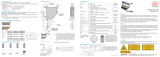
The following warning labels are attached to the sensor cable.
LASER RADIATION
DO NOT STARE INTO BEAM
CLASS 2 LASER PRODUCT
IEC 60825-1: 2014
P 1mW; =670nm
COMPLIES WITH 21 CFR 1040.10 AND 1040.11
EXCEPT FOR CONFORMANCE WITH IEC 60825-1
ED. 3., AS DESCRIBED IN
LASER NOTICE NO. 56, DATED MAY 8, 2019.
LASERSTRAHLUNG
NICHT IN DEN STRAHL BLICKEN
LASER KLASSE 2
nach DIN EN 60825-1: 2015-07
P 1mW; =670nm
Fig. 1 Laser labels on the sensor cable

Page 13
Laser Safety
optoNCDT 1420
Fig. 2 Laser warning sign on the sensor housing
During operation of the sensor, the pertinent regulations according to IEC 60825-1 on „Safety of laser prod-
ucts“ must be fully observed at all times. The sensor complies with all applicable laws for the manufacturer of
laser devices.
Laser operation is indicated by LED, see Chap. 5.3.
LASER RADIATION
DO NOT STARE INTO BEAM
CLASS 2 LASER PRODUCT
IEC 60825-1: 2014
P 1mW; =670nm
COMPLIES WITH 21 CFR 1040.10 AND 1040.11
EXCEPT FOR CONFORMANCE WITH IEC 60825-1
ED. 3., AS DESCRIBED IN
LASER NOTICE NO. 56, DATED MAY 8, 2019.
Fig. 3 Sensor cable and sensor with laser sign, ILD1420
i
If both warning labels are covered over when the unit is installed, the user must ensure that supplemen-
tary labels are applied.

Page 14
Laser Safety
optoNCDT 1420
2.2 ILD1420 CL1
The ILD1420 CL1 sensors operate with a semiconductor laser with a wavelength of 670 nm (visible/red).
The sensors fall within Laser Class 1 (I). The maximum optical power is ≤ 0.39 mW.
The accessible radiation is harmless under predictable conditions. Impairment of color vision and inconve-
nience may not excluded for class 1 laser devices, e. g. through glare.
The following warning labels are attached to the sensor cable:
CLASS 1 LASER PRODUCT
IEC 60825-1: 2014
P 0.39 mW; =670 nm≤
COMPLIES WITH 21 CFR 1040.10 AND 1040.11
EXCEPT FOR CONFORMANCE WITH IEC 60825-1
ED. 3., AS DESCRIBED IN
LASER NOTICE NO. 56, DATED MAY 8, 2019.
LASER KLASSE 1
nach DIN EN 60825-1: 2015-07
P 0,39 mW; =670 nm≤
Fig. 4 Laser labels on the sensor cable Fig. 5 Laser warning sign
on the sensor housing
Consequently, you can use Class 1 laser equipment without further protective measures. Class 1 lasers are
not subject to registration and a laser protection officer is not required. Laser operation is indicated by LED,
see Chap. 5.3. The housing of the optical sensors may only be opened by the manufacturer, see Chap. 11.
For repair and service purposes the sensors must always be sent to the manufacturer.
CLASS 1 LASER PRODUCT
IEC 60825-1: 2014
P 0.39 mW; =670 nm≤
COMPLIES WITH 21 CFR 1040.10 AND 1040.11
EXCEPT FOR CONFORMANCE WITH IEC 60825-1
ED. 3., AS DESCRIBED IN
LASER NOTICE NO. 56, DATED MAY 8, 2019.
Fig. 6 Sensor cable and sensor with laser sign, ILD1420 CL1

Page 15
Functional Principle, Technical Data
optoNCDT 1420
3. Functional Principle, Technical Data
3.1 Short Description
The optoNCDT 1420 uses the principle of optical triangulation, that is, a visible, modulated point of light is
projected onto the target surface.
The diffuse part of the reflection of this point of light is displayed depending on distance on a position-resolv-
ing element (CMOS) by an receiver optic which is arranged to the optical axis of the laser beam in a defined
angle.
A signal processor in the sensor calculates the distance of the point of light on the measuring object to the
sensor by means of the output signal of the CMOS elements. The distance value is linearized and output by
means of the analog or RS422 interface.
SMRMR
optoNCDT
Current output Digital value
1
3 mA 262077
4 mA (SMR) 643
12 mA (MMR) 32765
20 mA (EMR 64887
3 mA 262078
MR = Measuring range
SMR = Start of measuring range
MMR = Mid of measuring range
EMR = End of measuring range
Fig. 7 Definition of terms
1) For distance values without zero setting or mastering only

Page 16
Functional Principle, Technical Data
optoNCDT 1420
3.2 Auto Target Compensation (ATC)
The Auto Target Compensation (ATC) enables stable compensation independent of color and brightness of
the measuring object. Also small objects can be detected reliably thanks to the small measuring spot.

Page 17
Functional Principle, Technical Data
optoNCDT 1420
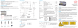
3.3 Technical Data ILD1420
Model ILD1420-10 ILD1420-25 ILD1420-50 ILD1420-100 ILD1420-200 ILD1420-500
Measuring range 10 mm 25 mm 50 mm 100 mm 200 mm 500 mm
Start of measuring range 20 mm 25 mm 35 mm 50 mm 60 mm 100 mm
Mid of measuring range 25 mm 37.5 mm 60 mm 100 mm 160 mm 350 mm
End of measuring range 30 mm 50 mm 85 mm 150 mm 260 mm 600 mm
Measuring rate
1
5 adjustable stages: 4 kHz/2 kHz/1 kHz/0.5 kHz/0.25 kHz
Linearity
≤ ±8 µm ≤ ±20 µm ≤ ±40 µm ≤ ±80 µm ≤ ±160 µm ≤ ±500 µm
≤ ±0.08 % FSO ≤ ±0.1 % FSO
Repeatability
2
0.5 µm 1 µm 2 µm 4 µm 8 µm 20 ... 40 µm
Temperature stability ±0.015 % FSO/K ±0.01 % FSO/K
Light spot diameter
(±10 %)
SMR 90 x 120 µm 100 x 140 µm 90 x 120 µm
750 x 1100 µm 750 x 1100 µm 750 x 1100 µmMMR 45 x 40 µm 120 x 130 µm 230 x 240 µm
EMR 140 x 160 µm 390 x 500 µm 630 x 820 µm
smallest ø
45 x 40 µm
with 24 mm
55 x 50 µm
with 31 mm
70 x 65 µm
with 42 mm
- - -
Light source Semiconductor laser < 1 mW, 670 nm (red)
Laser safety class Class 2 in accordance with IEC 60825-1: 2014
Permissible ambient light
3
50,000 lx 30,000 lx 10,000 lx
Supply voltage 11 ... 30 VDC
Power consumption < 2 W (24 V)
Signal input
1 x HTL laser on/off;
1 x HTL multifunction input: trigger in, zero setting, mastering, teach
Digital interface
RS422 (16 bit), PROFINET
4
, EtherNet/IP
4

Page 18
Functional Principle, Technical Data
optoNCDT 1420
Analog output
4 … 20 mA/1 … 5 V with cable PCF1420-3/U
(12 bit; freely scalable within the measuring range)
5
Switching output 1 x error output: npn, pnp, push pull
Connection
integrated cable 3 m, open ends, minimum bending radius 30 mm (fixed installation) or integrat-
ed pigtail 0.3 m with 12-pin M12 connector (see accessories for suitable connection cable)
Mounting Screw connection via two mounting holes
Temperature range
Operation 0 ... +50 °C (+32 ... +122 °F) (non-condensing)
Storage -20 ... +70 °C (-4 ... +158 °) (non-condensing)
Shock (DIN-EN 60068-2-29) 15 g/6 ms in 3 axes, 1000 shocks each
Vibration (DIN-EN 60068-2-6) 20 g/20 ... 500 Hz in 3 axes, 2 directions and 10 cycles each
Protection class (DIN-EN 60529) IP65
Material Aluminium housing
Weight approx. 60 g (incl. pigtail), approx. 145 g (incl. cable)
Control and display elements
Select button: zero, teach, factory setting;
web interface for setup
6
: selectable presets, peak selection, video signal,
freely selectable averaging possibilities, data reduction, setup management;
2 x color LEDs for power/status
FSO = Full Scale Output
SMR = Start of measuring range; MMR = Mid of measuring range; EMR = End of measuring range
The specified data apply to a white, diffuse reflecting surface (Micro-Epsilon reference ceramic for ILD sensors)
1) Factory setting 2 kHz, modifying the factory setting requires the IF2001/USB converter (see accessories)
2) Measuring rate 2 kHz, median 9
3) Illuminant: light bulb
4) Connection via interface module (see accessories)
5) D/A conversion is executed with 12 bit
6) Connection to PC via IF2001/USB (see accessories)

Page 19
Functional Principle, Technical Data
optoNCDT 1420
3.5 Technical Data ILD1420-CL1
Model ILD1420-10CL1 ILD1420-25CL1 ILD1420-50CL1
Measuring range 10 mm 25 mm 50 mm
Start of measuring range 20 mm 25 mm 35 mm
Mid of measuring range 25 mm 37,5 mm 60 mm
End of measuring range 30 mm 50 mm 85 mm
Measuring rate
1
5 adjustable stages: 4 kHz/2 kHz/1 kHz/0.5 kHz/0.25 kHz
Linearity
≤ ±8 µm ≤ ±20 µm ≤ ±40 µm
≤ ±0.08 % FSO
Repeatability
2
0.5 µm 1 µm 2 µm
Temperature stability ± 0.015 % FSO/K
Light spot diameter
(±10 %)
SMR 90 x 120 µm 100 x 140 µm 90 x 120 µm
MMR 45 x 40 µm 120 x 130 µm 230 x 240 µm
EMR 140 x 160 µm 390 x 500 µm 630 x 820 µm
smallest ø 45 x 40 µm with 24 mm 55 x 50 µm with 31 mm 70 x 65 µm with 42 mm
Light source Semiconductor laser ≤ 0.39 mW, 670 nm (red)
Laser safety class Class 1 in accordance with IEC 60825-1: 2014
Permissible ambient light
3
15,000 lx
Supply voltage 11 ... 30 VDC
Power consumption < 2 W (24 V)
Signal input
1 x HTL laser on/off;
1 x HTL multifunction input: trigger in, zero setting, mastering, teach
Digital interface
RS422 (16 bit), PROFINET
4
, EtherNet/IP
4
Analog output
4 … 20 mA; 1 … 5 V with cable PCF1420-3/U
(12 bit; freely scalable within the measuring range)
5

Page 20
Functional Principle, Technical Data
optoNCDT 1420
Switching output 1 x error output: npn, pnp, push pull
Connection
integrated cable 3 m, open ends, minimum bending radius 30 mm (fixed installation) or integrat-
ed pigtail 0.3 m with 12-pin M12 connector (see accessories for suitable connection cable)
Mounting Screw connection via two mounting holes
Temperature range
Operation 0 ... +50 °C (+32 ... +122 °F) (non-condensing)
Storage -20 ... +70 °C (-4 ... +158 °) (non-condensing)
Shock (DIN-EN 60068-2-29) 15 g / 6 ms in 3 axes, 1000 shocks each
Vibration (DIN-EN 60068-2-6) 20 g / 20 ... 500 Hz in 3 axes, 2 directions and 10 cycles each
Protection class(DIN-EN 60529) IP65
Material Aluminium housing
Weight approx. 60 g (incl. pigtail), approx. 145 g (incl. cable)
Control and display elements
Select button: zero, teach, factory setting;
web interface for setup
6
: selectable presets, peak selection, video signal,
freely selectable averaging, data reduction, setup management;
2 x color LEDs for power/status
FSO = Full Scale Output
SMR = Start of measuring range; MMR = Mid of measuring range; EMR = End of measuring range
The specified data apply to a white, diffuse reflecting surface (Micro-Epsilon reference ceramic for ILD sensors)
1) Factory setting 2 kHz, modifying the factory setting requires the IF2001/USB converter (see accessories)
2) Measuring rate 2 kHz, median 9
3) Illuminant: light bulb
4) Connection via interface module (see accessories)
5) D/A conversion is executed with 12 bit
6) Connection to PC via IF2001/USB (see accessories)
/