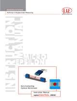
MICRO-EPSILON optoCONTROL 2520 User manual

Category
Measuring & layout tools
Type
User manual
MICRO-EPSILON Eltrotec GmbH
Manfred-Wörner-Straße 101 · 73037 Göppingen / Germany
Tel. +49 (0) 7161 / 98872-300 · Fax +49 (0) 7161 / 98872-303
[email protected] · www.micro-epsilon.com
Your local contact: www.micro-epsilon.com/contact/worldwide/
optoCONTROL 2520-46
optoCONTROL 2520-46(090)
optoCONTROL 2520-95
optoCONTROL 2520-95(270)
Operating Instructions
optoCONTROL 2520
MICRO-EPSILON
Eltrotec GmbH
Manfred-Wörner-Straße 101
73037 Göppingen / Germany
Tel. +49 (0) 7161 / 98872-300
Fax +49 (0) 7161 / 98872-303
www.micro-epsilon.com
Laser micrometer
optoCONTROL 2520
Contents
1. Safety ........................................................................................................................................ 9
1.1 Symbols Used ................................................................................................................................................. 9
1.2 Warnings .......................................................................................................................................................... 9
1.3 Notes on CE Marking ...................................................................................................................................... 9
1.4 Intended Use ................................................................................................................................................. 10
1.5 Proper Environment ....................................................................................................................................... 10
2. Laser Safety ............................................................................................................................ 11
3. Functional Principle, Technical Data ..................................................................................... 13
3.1 Short Description ........................................................................................................................................... 13
3.2 Measurement Principle .................................................................................................................................. 14
3.3 Block Diagram ............................................................................................................................................... 14
3.4 Functions ....................................................................................................................................................... 15
3.5 Operating Modes ........................................................................................................................................... 16
3.6 Technical Data ODC2520-46 ......................................................................................................................... 17
3.7 Technical Data ODC2520-95 ......................................................................................................................... 18
4. Delivery ................................................................................................................................... 19
4.1 Unpacking, Included in Delivery.................................................................................................................... 19
4.2 Notes about Cables ....................................................................................................................................... 19
4.3 Storage .......................................................................................................................................................... 19
5. Mounting ................................................................................................................................. 20
5.1 General .......................................................................................................................................................... 20
5.2 Light Source and Receiver ............................................................................................................................ 20
5.2.1 Dimensions ................................................................................................................................... 20
5.2.2 Mounting on DIN-Rail ................................................................................................................... 23
5.2.3 Free Mounting .............................................................................................................................. 24
5.2.4 Calibrated Measuring Distances .................................................................................................. 25
5.3 Electrical Connections ................................................................................................................................... 26
5.3.1 Receiver ........................................................................................................................................ 26
5.3.2 Light Source ................................................................................................................................. 27
5.3.3 Connection Possibilities ............................................................................................................... 28
5.3.4 Power Supply, Inputs/Outputs, RS422 ........................................................................................ 29
5.3.5 Power Supply ............................................................................................................................... 30
5.3.6 Ethernet, EtherCAT ....................................................................................................................... 30
5.3.7 Wiring Switching Input ................................................................................................................. 31
5.3.8 Wiring of the Switching Outputs................................................................................................... 31
5.4 LEDs on Receiver .......................................................................................................................................... 32
6. Operation ................................................................................................................................ 33
6.1 Initial Operation .............................................................................................................................................. 33
6.2 Control via Ethernet ....................................................................................................................................... 33
6.2.1 Requirements ............................................................................................................................... 33
6.2.2 Access via Ethernet ..................................................................................................................... 35
6.2.3 Measuring Value Presentation with Ethernet (Web Browser) ...................................................... 35
6.3 Video Signal ................................................................................................................................................... 36
6.3.1 Light Source Reference ................................................................................................................ 36
6.3.2 Video Signal, Edge Detection ...................................................................................................... 37
6.4 User Interface, Basic Preferences ................................................................................................................. 39
6.4.1 Introduction .................................................................................................................................. 39
6.4.2 Measurement Distance................................................................................................................. 39
6.4.3 Measurement Program ................................................................................................................. 39
6.4.3.1 Definitions .................................................................................................................... 39
6.4.3.2 Program Selection ....................................................................................................... 41
6.4.3.3 Change Search and Measuring Direction of Edges ................................................... 42
6.5 Measurements with Web Page Display ......................................................................................................... 43
6.6 Save / Load Settings in Sensor ..................................................................................................................... 45
6.6.1 Preliminary Remarks .................................................................................................................... 45
6.6.2 Save in Sensor ............................................................................................................................. 45
6.6.3 Load from the Sensor ................................................................................................................... 45
7. Advanced Settings ................................................................................................................. 46
7.1 Login, Switching User Level .......................................................................................................................... 46
7.1.1 Preliminary Remarks to Password Protection .............................................................................. 46
7.1.2 Change User Level ....................................................................................................................... 46
7.1.3 Password Assignment .................................................................................................................. 47
7.2 Measurement Program Segments ................................................................................................................ 48
7.2.1 Preliminary Remark ...................................................................................................................... 48
7.2.2 Definition of Segments ................................................................................................................. 48
7.3 Averaging / Error Handling / Spike Correction / Statistics ............................................................................ 49
7.3.1 Notes on Averaging ...................................................................................................................... 49
7.3.2 Processing Sequence .................................................................................................................. 49
7.3.3 Measuring Value Averaging ......................................................................................................... 50
7.3.4 Error Handling (Hold Last Value) ................................................................................................. 52
7.3.5 Spike Correction ........................................................................................................................... 53
7.3.6 Statistics ....................................................................................................................................... 54
optoCONTROL 2520
7.4 Zeroing / Mastering........................................................................................................................................ 55
7.4.1 General ......................................................................................................................................... 55
7.4.2 Setting Zeroing / Masters ............................................................................................................. 55
7.4.3 Mastering or Zeroing via Switching Input (In) .............................................................................. 56
7.5 Digital Interfaces ............................................................................................................................................ 57
7.5.1 Overview Menu Structure ............................................................................................................. 57
7.5.2 Select Digital Interfaces ................................................................................................................ 57
7.5.3 Select Data ................................................................................................................................... 58
7.5.4 Ethernet ........................................................................................................................................ 59
7.5.5 RS422 ........................................................................................................................................... 59
7.6 Switching Outputs ......................................................................................................................................... 60
7.6.1 General ......................................................................................................................................... 60
7.6.2 Assignments of the Switch Outputs (Digital I/O) ......................................................................... 60
7.6.3 Limit Value Settings ...................................................................................................................... 61
7.6.4 Switch Behavior of Error Outputs ................................................................................................. 61
7.7 Analog Output ................................................................................................................................................ 62
7.7.1 General ......................................................................................................................................... 62
7.7.2 Setting Analog Output .................................................................................................................. 62
7.7.3 Two-Point Scaling ......................................................................................................................... 63
7.8 Output Data Rate ........................................................................................................................................... 63
7.9 Trigger Mode .................................................................................................................................................. 64
7.9.1 Preliminary Remarks .................................................................................................................... 64
7.9.2 Setting the Trigger Mode .............................................................................................................. 64
7.9.3 Triggering the Measuring Value Output Recording ..................................................................... 66
7.9.4 Triggering the Measuring Value Output ....................................................................................... 66
7.9.5 Example ........................................................................................................................................ 66
7.10 Synchronization ............................................................................................................................................. 67
7.11 Manage Setups on PC................................................................................................................................... 68
7.12 Extras ............................................................................................................................................................. 69
7.12.1 Set Factory Settings ..................................................................................................................... 69
7.12.2 Reset the Sensor ......................................................................................................................... 69
7.12.3 Select Measuring Unit .................................................................................................................. 70
7.13 Masking Evaluation Range ............................................................................................................................ 70
7.14 Help / Info ...................................................................................................................................................... 71
7.15 Timing, Measuring Value Flux ....................................................................................................................... 71
8. Errors, Repair ......................................................................................................................... 72
8.1 Communication ............................................................................................................................................. 72
8.2 Optical Influences .......................................................................................................................................... 72
8.2.1 Pollutions ...................................................................................................................................... 72
8.2.2 Ambient Light ............................................................................................................................... 72
8.2.3 Shadowing of the Laser Light ...................................................................................................... 73
8.2.4 Temperature Differences .............................................................................................................. 74
8.2.5 Edge Jumps ................................................................................................................................ 74
8.2.6 Thin Targets .................................................................................................................................. 75
8.2.7 Transparent Targets ...................................................................................................................... 76
8.2.8 Wrong Edge Number .................................................................................................................. 76
9. Software Update ..................................................................................................................... 77
9.1 Procedure ...................................................................................................................................................... 77
9.2 Troubleshooting ............................................................................................................................................. 77
10. Software Support with MEDAQLib ....................................................................................... 78
11. ODC Demo Tool ...................................................................................................................... 78
12. Liability for Material Defects .................................................................................................. 79
13. Service, Repair ...................................................................................................................... 79
14. Decommissioning, Disposal ................................................................................................. 79
optoCONTROL 2520
Appendix
A 1 Optional Accessories ............................................................................................................. 80
A 2 Factory Setting ....................................................................................................................... 83
A 2.1 Parameter ....................................................................................................................................................... 83
A 2.2 Set Default Settings ....................................................................................................................................... 84
A 3 Demo Tool for Recording Measurement Data ....................................................................... 85
A 4 Software sensorTOOL ............................................................................................................ 85
A 5 RS422, Connection to RS422 Converter ............................................................................... 86
A 5.1 IF2001/USB Converter ................................................................................................................................... 86
A 5.2 IF2004/USB 4-Channel RS422/USB Converter ............................................................................................. 86
A 5.3 RS422-USB Converter ................................................................................................................................... 86
A 6 ASCII Communication ............................................................................................................ 87
A 6.1 General .......................................................................................................................................................... 87
A 6.2 Commands Overview .................................................................................................................................... 87
A 6.3 General Commands ..................................................................................................................................... 90
A 6.3.1 General ......................................................................................................................................... 90
A 6.3.1.1 Help ............................................................................................................................ 90
A 6.3.1.2 Sensor Information ...................................................................................................... 90
A 6.3.1.3 Reply Type ................................................................................................................... 90
A 6.3.1.4 Parameter Overview ................................................................................................... 90
A 6.3.1.5 Synchronization .......................................................................................................... 91
A 6.3.1.6 Booting the Sensor .................................................................................................... 91
A 6.3.2 User Level ..................................................................................................................................... 91
A 6.3.2.1 Changing the User Level ............................................................................................ 91
A 6.3.2.2 Changing to User Level ............................................................................................... 91
A 6.3.2.3 Querying the User Level ............................................................................................. 91
A 6.3.2.4 Setting the User Level on Restart (Standard User) ................................................... 91
A 6.3.2.5 Changing the Password ............................................................................................. 92
A 6.3.3 Video Signal ................................................................................................................................. 92
A 6.3.3.1 Light Correction ........................................................................................................... 92
A 6.3.3.2 Edge Detection Threshold .......................................................................................... 92
A 6.3.3.3 Reduction of Region of Interest .................................................................................. 92
A 6.4 Measurement ................................................................................................................................................. 92
A 6.4.1 Measurement Distance Calibration Tables .................................................................................. 92
A 6.4.1.1 Calibration Selection for a Measuring Distance ......................................................... 92
A 6.4.1.2 Current Calibration Table for a Measuring Distance ................................................... 92
A 6.4.1.3 Table of all Calibrated Measuring Distances............................................................... 93
A 6.4.2 Setting the Measurement Task ..................................................................................................... 93
A 6.4.2.1 Measurement Program Selection ............................................................................... 93
A 6.4.2.2 Search Direction Edges .............................................................................................. 93
A 6.4.2.3 Measuring Direction Edges ......................................................................................... 93
A 6.4.2.4 Number of Expected Edges ........................................................................................ 93
A 6.4.2.5 Definition of Segments ................................................................................................ 94
A 6.4.2.6 Signal Names .............................................................................................................. 94
A 6.4.3 Measuring Value Processing ........................................................................................................ 95
A 6.4.3.1 Averaging of Measuring Value .................................................................................... 95
A 6.4.3.2 Spike Correction ......................................................................................................... 95
A 6.4.3.3 Error Processing ......................................................................................................... 95
A 6.4.3.4 Selection of the Measuring Value for the 1
st
Statistics ................................................ 95
A 6.4.3.5 Selection of the Measuring Value for the 2
nd
Statistics ............................................... 95
A 6.4.3.6 Setting the Statistics Calculation ................................................................................ 95
A 6.4.3.7 Resetting the Statistics Calculation ............................................................................. 96
A 6.4.3.8 Selection of Measuring Value for Mastering / Zeroing ............................................... 96
A 6.4.3.9 Mastering / Zeroing ..................................................................................................... 96
A 6.5 Data Output via Digital Interfaces .................................................................................................................. 96
A 6.5.1 Interface Settings .......................................................................................................................... 96
A 6.5.1.1 Selection Digital Output .............................................................................................. 96
A 6.5.1.2 Ethernet IP Settings ..................................................................................................... 96
A 6.5.1.3 Setting for Ethernet Measuring Value Transmitting ................................................... 97
A 6.5.1.4 Setting RS422 Baud Rate ........................................................................................... 97
A 6.5.1.5 Change Ethernet / EtherCAT....................................................................................... 97
A 6.5.1.6 Reduce the Output Data Rate ..................................................................................... 97
A 6.5.2 Select Measuring Values to be Output ........................................................................................ 98
A 6.5.2.1 Preliminary Remarks on the Measuring Value Selection ............................................ 98
A 6.5.2.2 Output of Measuring Values Edge Low-High via RS422 and Ethernet ...................... 98
A 6.5.2.3 Output of the Measuring Values Edge High-Low via RS422 and Ethernet ................ 98
A 6.5.2.4 Output of the Diameter Data via RS422 and via Ethernet .......................................... 98
A 6.5.2.5 Output of the Gap Data via RS422 and Ethernet ........................................................ 98
A 6.5.2.6 Output of the Segment Data via RS422 and Ethernet ................................................ 99
A 6.5.2.7 Output of the Additional Data via RS422 and Ethernet .............................................. 99
A 6.5.2.8 Output of the Statistics Data via RS422 and Ethernet ................................................ 99
A 6.5.2.9 Output of Video Signals via Ethernet .......................................................................... 99
A 6.5.3 Switching Outputs ...................................................................................................................... 100
A 6.5.3.1 Assignment of the Switch Outputs............................................................................ 100
A 6.5.3.2 Hold Period of Switching Outputs............................................................................. 100
A 6.5.3.3 Setting Limit Values ................................................................................................... 100
A 6.5.3.4 Switching Level (Active Level) ................................................................................... 100
optoCONTROL 2520
A 6.5.4 Analog Output ............................................................................................................................ 100
A 6.5.4.1 Data Selection for the Analog Output ....................................................................... 100
A 6.5.4.2 Disable / Enable the Analog Output ......................................................................... 101
A 6.5.4.3 Scaling of the Analog Output .................................................................................... 101
A 6.5.5 Triggering .................................................................................................................................... 101
A 6.5.5.1 Preliminary Remarks to the Triggering ..................................................................... 101
A 6.5.5.2 Trigger Type ............................................................................................................... 101
A 6.5.5.3 Effect of the Trigger Input .......................................................................................... 101
A 6.5.5.4 Trigger Level (Active Level of the Trigger Input) ....................................................... 101
A 6.5.5.5 Number of Output Measuring Values ....................................................................... 102
A 6.5.5.6 Software Trigger Pulse (Creating a Software Trigger Signal) ................................... 102
A 6.5.6 Parameter Management, Load / Save Settings ......................................................................... 102
A 6.5.6.1 Save Parameter Set ................................................................................................... 102
A 6.5.6.2 Load Parameter Set .................................................................................................. 102
A 6.5.6.3 Reset to Factory Settings .......................................................................................... 102
A 6.5.6.4 Measuring Unit Web Interface ................................................................................... 102
A 6.5.7 Measuring Data .......................................................................................................................... 103
A 6.5.7.1 Measuring Value Format ........................................................................................... 103
A 6.5.7.2 Video Signal .............................................................................................................. 104
A 6.5.7.3 Measuring Value Counter .......................................................................................... 104
A 6.5.7.4 Time Stamp .............................................................................................................. 104
A 6.5.7.5 Number of Edges ..................................................................................................... 104
A 6.5.7.6 Number of Pins ........................................................................................................ 104
A 6.5.7.7 Number of Gaps ....................................................................................................... 104
A 6.5.7.8 Status......................................................................................................................... 105
A 6.5.7.9 Measuring Data ......................................................................................................... 106
A 6.5.7.10 Statistic Values ......................................................................................................... 106
A 6.5.8 Measuring Data Format .............................................................................................................. 107
A 6.5.8.1 Data Format RS422 Interface .................................................................................... 107
A 6.5.8.2 Error Codes RS422 Interface .................................................................................... 107
A 6.5.8.3 Measuring Data Transmission to a Measuring Value Server via Ethernet................ 108
A 6.5.8.4 Error Codes Ethernet Interface ................................................................................. 110
A 6.5.8.5 Ethernet Video Signal Transmission ......................................................................... 110
A 6.6 Warning and Error Messages ...................................................................................................................... 110
A 7 Telnet ..................................................................................................................................... 113
A 7.1 General ........................................................................................................................................................ 113
A 7.1.1 Requirement ............................................................................................................................... 113
A 7.1.2 Link Connection ......................................................................................................................... 113
A 7.1.3 Error Messages .......................................................................................................................... 113
A 7.2 Example ....................................................................................................................................................... 113
A 8 EtherCAT Documentation .................................................................................................... 114
A 8.1 General ........................................................................................................................................................ 114
A 8.2 Introduction .................................................................................................................................................. 114
A 8.2.1 Structure of EtherCAT®-Frames ................................................................................................ 114
A 8.2.2 EtherCAT® Services ................................................................................................................... 114
A 8.2.3 Addressing and FMMUs ............................................................................................................. 115
A 8.2.4 Sync Manager ............................................................................................................................ 115
A 8.2.5 EtherCAT State Machine ............................................................................................................ 116
A 8.2.6 CANopen over EtherCAT............................................................................................................ 116
A 8.2.7 Process Data PDO Mapping ...................................................................................................... 117
A 8.2.8 Service Data SDO Service .......................................................................................................... 118
A 8.3 CoE – Object Directory ................................................................................................................................ 118
A 8.3.1 Characteristics ............................................................................................................................ 118
A 8.3.2 Communication Specific Standard Objects (CiA DS-301) ........................................................ 118
A 8.3.2.1 Overview .................................................................................................................... 118
A 8.3.2.2 Object 1000h: Divice type ......................................................................................... 118
A 8.3.2.3 Object 1001h: Error register...................................................................................... 119
A 8.3.2.4 Object 1003h: Error history ....................................................................................... 119
A 8.3.2.5 Object 1008h: Device name ...................................................................................... 119
A 8.3.2.6 Object 1009h: Hardware version .............................................................................. 119
A 8.3.2.7 Object 100Ah: Software version ............................................................................... 119
A 8.3.2.8 Object 1018h: Identity ............................................................................................... 119
A 8.3.2.9 Object 1A00h: TxPDO mapping ............................................................................... 119
A 8.3.2.10 Object 1A01 up to 1A18: TxPDO mapping ............................................................... 119
A 8.3.2.11 Object 1C00h: Sync manager type .......................................................................... 120
A 8.3.2.12 Object 1C13h: TxPDO assign ................................................................................... 120
A 8.3.2.13 Object 1C33h: SM input manager ............................................................................ 120
optoCONTROL 2520
A 8.3.3 Manufacturer Specific Objects ................................................................................................... 121
A 8.3.3.1 Overview .................................................................................................................... 121
A 8.3.3.2 Object 2001h: User level ........................................................................................... 121
A 8.3.3.3 Object 2005h: Sensor informations .......................................................................... 122
A 8.3.3.4 Object 2010h: Setup ................................................................................................. 122
A 8.3.3.5 Object 2011h: Correction .......................................................................................... 122
A 8.3.3.6 Object 2050h: Advanced settings ............................................................................. 122
A 8.3.3.7 Object 2101h: Reset .................................................................................................. 122
A 8.3.3.8 Object 2105h: Factory settings ................................................................................. 123
A 8.3.3.9 Object 2132h: Laser power ....................................................................................... 123
A 8.3.3.10 Object 2153h: Measuring distance ........................................................................... 123
A 8.3.3.11 Object 2154h: Measuring program ........................................................................... 123
A 8.3.3.12 Object 2165h: Edges segment ................................................................................. 124
A 8.3.3.13 Object 2181h: Averaging, error processing and statistics ....................................... 125
A 8.3.3.14 Object 21B0h: Digital interfaces ............................................................................... 127
A 8.3.3.15 Object 21B1h: Value edge high-low ......................................................................... 127
A 8.3.3.16 Object 21B2h: Value edge low-high ......................................................................... 128
A 8.3.3.17 Object 21B3h: Value diameter .................................................................................. 128
A 8.3.3.18 Object 21B4h: Value gap .......................................................................................... 128
A 8.3.3.19 Object 21B5h: Value segment .................................................................................. 129
A 8.3.3.20 Object 21C0h: Ethernet............................................................................................. 130
A 8.3.3.21 Object 21D0h: Analog output ................................................................................... 130
A 8.3.3.22 Object 21E0h: Zeroing/Mastering ............................................................................. 131
A 8.3.3.23 Object 21F1h: Switching outputs.............................................................................. 132
A 8.3.3.24 Object 2410h: Trigger mode ..................................................................................... 133
A 8.3.3.25 Object 2550h: Threshold .......................................................................................... 133
A 8.3.3.26 Object 2711h: Range of interest ............................................................................... 133
A 8.3.3.27 Object 603Fh: Sensor error ...................................................................................... 134
A 8.3.3.28 Object 6060h: System values ................................................................................... 134
A 8.3.3.29 Object 6065h: Measuring value edge high-low ........................................................ 134
A 8.3.3.30 Object 6066h: Measuring value edge low-high ........................................................ 134
A 8.3.3.31 Object 6067h: Measuring values diameter ............................................................... 134
A 8.3.3.32 Object 6068h: Measuring values gap ....................................................................... 135
A 8.3.3.33 Object 6069h: Measuring values segment ............................................................... 135
A 8.4 Error Codes for SDO Services ..................................................................................................................... 136
A 8.5 Measurement Data Formats ........................................................................................................................ 137
A 8.6 Distributed Clock ......................................................................................................................................... 138
A 8.6.1 Introduction ................................................................................................................................ 138
A 8.6.2 Synchronization ......................................................................................................................... 138
A 8.6.3 Synchronization off ..................................................................................................................... 138
A 8.6.4 Slave ........................................................................................................................................... 138
A 8.6.5 Apply Selected Settings ............................................................................................................. 138
A 8.6.6 Setting Regardless of TwinCat ................................................................................................... 138
A 8.7 Oversampling............................................................................................................................................... 139
A 8.8 Meaning of STATUS-LED in EtherCAT Operation ....................................................................................... 144
A 8.9 EtherCAT Configuration with the Beckhoff TwinCAT© Manager ................................................................ 145
A 8.10 Exit EtherCAT ............................................................................................................................................... 150
A 9 Activate Ethernet Interface .................................................................................................. 151
Page 9
Safety
optoCONTROL 2520
1. Safety
System operation assumes knowledge of the operating instructions.
1.1 Symbols Used
The following symbols are used in these operating instructions.
CAUTION
Indicates a hazardous situation which, if not avoided, may result in
minor or moderate injury.
NOTICE
Indicates a situation that may result in property damage if not
avoided.
Indicates a user action.
i
Indicates a tip for users.
Measure
Indicates hardware or a button/menu.
1.2 Warnings
Connect the power supply and the display / output device according to the safety regula-
tions for electrical equipment.
> Risk of injury
> Damage to or destruction of the sensor
Avoid shocks and impacts to the light source and the receiver.
> Damage to or destruction of the light source / receiver
Protect the cables against damage.
> Failure of the measuring device
The supply voltage must not exceed the specified limits.
> Damage to or destruction of the sensor
Avoid damage (scratches) to the protective windows of the light source and receiver
through unsuitable cleaning-methods or cleaning solvents.
> Inaccurate, erroneous measuring values
Do not touch the protective windows of light source and receiver with the fingers. Wipe
off any fingerprints immediately.
> Inaccurate, erroneous measuring values
Avoid permanent action of splashed water on the light source and the receiver.
> Damage to or destruction of the sensor
Avoid exposure to aggressive materials (washing agent, cooling emulsions).
> Damage to or destruction of the sensor
1.3 Notes on CE Marking
The following apply to the optoCONTROL 2520:
- EU Directive 2014/30/EU
- EU Directive 2011/65/EU, “RoHS“ category 9
Products which carry the CE mark satisfy the requirements of the EU directives cited and
the relevant applicable harmonized European standards (EN) listed therein. The measur-
ing system is designed for use in industrial environments.
The EU Declaration of Conformity is available to the responsible authorities according to
EU Directive, article 10.
CAUTION
NOTICE
Page 10
Safety
optoCONTROL 2520
1.4 Intended Use
- The optoCONTROL 2520 is designed for use in the industrial and laboratory areas. It
is used for
measuring displacement, distance, position and thickness
in-process quality and dimensional testing
- The system must only be operated within the limits specified in the technical data, see
3.6, see 3.7.
- The system must be used in such a way that no persons are endangered or machines
and other material goods are damaged in the event of malfunction or total failure of
the system.
- Take additional precautions for safety and damage prevention in case of for safety-re-
lated applications.
1.5 Proper Environment
- Protection class: IP64; when plugged in or on the Ethernet socket with protec-
tive cap
1
i
The protection class is limited to water (no penetrating liquids, detergents or similar
aggressive media).
Use a protective housing if the effects of water are continuous.
Optical windows are excluded from protection class. Contamination leads to impairment
or failure of the function.
- Temperature range:
Operation: 0 ... +50 °C (+32 ... +122 °F)
Storage: -20 ... +70 °C (-4 ... +158 °F)
- Humidity: 5 - 95 % RH (non-condensing)
- Ambient pressure: Atmospheric pressure
1) For operation without Ethernet / EtherCAT cable, the protective cap for the M12 con-
nector must be plugged to achieve the IP degree of protection!
Page 11
Laser Safety
optoCONTROL 2520
2. Laser Safety
The optoCONTROL operates with a semiconductor laser with a wavelength of 670 nm
(visible / red). The maximum optical output power is 2 mW.
The sensors fall within laser class 1M.
The accessible radiation is harmless under predictable conditions.
Do not view the radiation with optical instruments (e.g., converging lenses, magnifying
glasses).
For class 1 laser devices, impairment of color vision and disturbances, e.g., from a glare
effect, cannot be excluded.
Consequently, you can use Class 1M laser equipment without further protective mea-
sures.
Lasers of Class 1M are not subject to notification and a laser protection officer is not
required.
The following warning labels must be attached to the cover (front and/or rear side) of the
sensor housing. The laser warning labels for Germany have already been attached. For
other non German speaking countries, an IEC standard label is included in delivery and
the versions valid for the user’s country must be attached before the device is put into
operation for the first time.
LASER RADIATION
DO NOT VIEW DIRECTLY
WITH TELESCOPE OPTICS
CLASS 1M LASER PRODUCT
IEC 60825-1: 2014
P2mW, E0.2mW/cm²; =670nm
Fig. 1 Laser warning sign and laser label
COMPLIES WITH 21 CFR 1040.10 AND 1040.11
EXCEPT FOR CONFORMANCE WITH
IEC 60825-1 ED. 3., AS DESCRIBED IN
LASER NOTICE NO. 56, DATED MAY 8, 2019
Fig. 2 Only for USA
I
Light curtain
optoCONTROL
LASER RADIATION
DO NOT VIEW DIREC TLY
WITH TELESCOPE O PTICS
CLASS 1M LASER PRODUCT
IEC 60825-1: 2014
P2mW, E0.2mW/cm²; =670nm
COMPLIES WITH 21 CFR 1040.10 AND 1040.11
EXCEPT FOR CONFORMANCE WITH
IEC 60825-1 ED. 3., AS DESCRIBED IN
LASER NOTICE NO. 56, DATED MAY 8, 2019
Fig. 3 Sensor with laser labels
The housing of the optical sensors may only be opened by the manufacturer, see 12.
For repair and service purposes, the sensors must always be sent to the manufacturer.
Page 12
Laser Safety
optoCONTROL 2520
COMPLIES WITH 21 CFR 1040.10 AND 1040.11
EXCEPT FOR CONFORMANCE WITH
IEC 60825-1 ED. 3., AS DESCRIBED IN
LASER NOTICE NO. 56, DATED MAY 8, 2019
LASE R RADI ATION
DO NO T VIEW D IRECTLY
WITH T ELESCOPE OPTIC S
CLAS S 1M LASE R PRODU CT
IEC 60825-1: 2014
P2mW, E0.2mW/cm²; O=670nm
Fig. 4 True reproduction of the light source optoCONTROL 2520-95 with its actual loca-
tion of the warning label.
i
If both warning labels are covered over when the unit is installed the user must
ensure that supplementary labels are applied.
Page 13
Functional Principle, Technical Data
optoCONTROL 2520
3. Functional Principle, Technical Data
3.1 Short Description
optoCONTROL 2520 is a laser-based sensor with an integral high resolution line scan
camera for the measurement of geometrical quantities such as gap, edge position and
diameter. By the high measuring rate and exactness measurements are also possible in
quick processes.
The optoCONTROL 2520 sensor consists of a light source and a receiver, which are con-
nected about a three-pole connection cable with each other. The receiver contains also
the whole controller.
Receiver
Light source
Fig. 5 Sensor optoCONTROL 2520-46
Receiver
Light source
Fig. 6 Sensor optoCONTROL 2520-95
Page 14
Functional Principle, Technical Data
optoCONTROL 2520
3.2 Measurement Principle
The optoCONTROL 2520 measures the dimension of a target or the position of an edge
on a body according to the shadow principle and without making physical contact.
A parallel light curtain is produced with the laser light source, which sends a very homo-
geneous light by the high-quality illumination optics. The laser light source disposes of
no moved parts, so that the sensor works nearly non-expendable.
Light source
Laser diode Lens ODC lineTarget
Receiver
Fig. 7 Measurement principle optoCONTROL 2520
The ODC line in the receiver reproduces the shadow principle of the target with high
accuracy.
3.3 Block Diagram
Input/Output
Digital
Analog
Switching outputs
+24 VDCPower supply
ReceiverLight source
ODC 2520
Signal processorLaser
CMOS
ODC line
Light curtain
Fig. 8 Block diagram sensor ODC 2520
The integrated electronics evaluates the signal of the ODC line and outputs the measu-
ring values via the analog and digital interfaces.
For parametrization a web interface (Ethernet) and ASCII commands are available.
Page 15
Functional Principle, Technical Data
optoCONTROL 2520
3.4 Functions
The optoCONTROL 2520 sensor supports the following functions:
- Edge measurement in shadow principle procedures (edge low-high; edge high-low)
- Diameter, width, gap width measurement
- Any segment situations or widths
- Freely selectable edges
- Direction of counting switchable
- Calculation of central axes between edges
- Counting of edges and segments (pins or gaps)
- Web diagram with user levels via web interface
- Ethernet / EtherCAT
- Data logger function
- Define the measurement range (to hide protruding machine parts)
- Triggering and synchronization
- Adjustable threshold
- Statistic values such as Min / Max, Peak to Peak and various types of averaging
- Output of up to 8 segments, 16 edge positions and their center axis at the same time
Page 16
Functional Principle, Technical Data
optoCONTROL 2520
3.5 Operating Modes
Diagram Operating Mode Description
Position / edge
Light source
Receiver
Edge low-high Position of first low-high edge
(Distance to beginning of line)
Position / edge
Light source
Receiver
Edge high-low Position of first high-low edge
(Distance to beginning of line)
Diameter
Receiver
Light source
Diameter / width Measure, position and central axis of
an outer diameter or width of a metal
(first low-high and last high-low edge)
Gap
Receiver
Light source
Gap Measure, position and central axis of
a gap
(first high-low edge and next edge)
Segment
Receiver
Light source
Any segments Differences, positions and middle axis
of any edges
Fig. 9 Operating modes optoCONTROL 2520
You will find further informations to selection and parametrization at the measuring pro-
grams, see 6.4.3.
Page 17
Functional Principle, Technical Data
optoCONTROL 2520
3.6 Technical Data ODC2520-46
Model ODC2520-46 ODC2520-46(090)
Measuring range 46 mm
Min. target size typ. ≥ 0.5 mm
Distance of light source - receiver
(free space)
With mounting rail 100 … 300 mm;
without mounting rail free to 2000 mm
Measuring distance
(measured object - receiver)
20 mm ... 2000 mm; optimum distances: 20, 50, 100, 150 mm
Measuring rate 2.5 kHz
Resolution
1
1 µm
Linearity
2
< ±12 µm
Repeatability
3
≤ 5 µm
Light source Semiconductor laser 670 nm (red)
Laser safety class
Laser class 1M (P
max
2 mW) according to DIN EN 60825-1: 2014
Permissible ambient light Approx. 20.000 lx
Analog output 0 … +10 V not electrically separated, 14 Bit D/A
Digital interface
RS 422 (max. 4 MBaud), full duplex, not electrically separated;
Ethernet, electrically separated
EtherCAT / EtherNet/IP
5
/ PROFINET
5
Switching output
2 outputs, optionally for errors or limits,
not electrically separated, 24 V logic (HTL),
High level depends on operating voltage
Signal input
Zeroing/mastering, resetting to factory defaults; not electrically separated,
24 V logic (HTL), High level depends on operating voltage;
Trigln / Syncln (via RS422 level)
Digital output
SyncOut symmetrcal, RS422 level, terminating resistor (120 Ohm) and
can be switched using software, not electrically separated
Connection
Receiver
3-pin socket M8 for supply of light source,
14-pin socket M16 for power supply & signals,
4-pin socket M12x1 for Ethernet /EtherCAT
Light source 3-pin socket M8 for supply
Mounting Mounting rail (see accessories), mounting holes
Temperature range
Storage -20 ... +70 °C (-4 ... +158 °F)
Operation 0 ... +50 °C (+41 ... +122 °F)
Supply voltage +24 VDC (11…30 VDC)
Max. current consumption < 1 A
Shock (DIN-EN 60068-2-27) 15 g / 6 ms
Vibration (DIN-EN 60068-2-6) 2 g / 20 … 500 Hz
Protection class
(DIN-EN 60529)
Receiver /
light source
IP64
Material
Receiver /
light source
Aluminum housing
Weight 1.25 kg (without cable)
Measuring programs
Edge light-dark; edge dark-light;
(outside) diameter / width incl. edges & center axis
gap / (inside diameter) incl. edges & center axis;
any segments incl. segment edges & center axes
Control and display elements
Web interface for setting parameters and display;
color LEDs for Power on, Status, Speed, Link/activity
Features
Measurements server for transmission of several measure-
ments to the PC;
(optional other periphery devices, see operating instructions)
The data listed are for a consistent room temperature of 20 °C, sensor operating constantly, signal outputs open and
sensor mounted on included mounting rail.
Measured at light source - receiver 300 mm, measured object - receiver distance 20 mm, operating mode: Edge light-
dark
1) At the digital interface
2) Linearity (for distances between target and receiver, measured with 3 s: 20 mm < ±12 µm / 50 mm < ±12 µm /
100 mm < ±15 µm / 150 mm < ±15 µm
3) Measured with a moving average over 32 values
4) Smallest detectable object, not measurable
5) Connection via interface module (see accessories)
Page 18
Functional Principle, Technical Data
optoCONTROL 2520
3.7 Technical Data ODC2520-95
Model ODC2520-95 ODC2520-95(270)
Measuring range 95 mm
Min. target size typ. ≥ 2.0 mm / 100 µm
4
Distance of light source - receiver
(free space)
With mounting rail 100 … 300 mm;
without mounting rail free to 2000 mm
Measuring distance
(measured object - receiver)
20 mm ... 2000 mm; optimum distances: 20, 50, 100, 150 mm
Measuring rate 2.0 kHz
Resolution
1
2 µm
Linearity
2
< ±15 µm
Repeatability
3
≤ 6 µm
Light source Semiconductor laser 670 nm (red)
Laser safety class Laser class 1M (P
max
2 mW) according to DIN EN 60825-1: 2014
Permissible ambient light Approx. 15.000 lx
Analog output 0 … +10 V not electrically separated, 14 Bit D/A
Digital interface RS 422 (max. 4 MBaud), full duplex, not electrically separated;
Ethernet, electrically separated
EtherCAT / EtherNet/IP
5
/ PROFINET
5
Switching output 2 outputs, optionally for errors or limits,
not electrically separated, 24 V logic (HTL),
High level depends on operating voltage
Signal input Zeroing/mastering, resetting to factory defaults; not electrically separated,
24 V logic (HTL), High level depends on operating voltage;
Trigln / Syncln (via RS422 level)
Digital output SyncOut symmetrcal, RS422 level, terminating resistor (120 Ohm) and can
be switched using software, not electrically separated
Connection Receiver 3-pin socket M8 for supply of light source,
14-pin socket M16 for power supply & signals,
4-pin socket M12x1 for Ethernet /EtherCAT
Light source 3-pin socket M8 for supply
Mounting Mounting rail (see accessories), mounting holes
Temperature
range
Storage -20 ... +70 °C (-4 ... +158 °F)
Operation 0 ... +50 °C (+32 ... +122 °F)
Supply voltage +24 VDC (11 … 30 VDC)
Max. current consumption < 1 A
Shock (DIN-EN 60068-2-27) 6 g / 6 ms in X, Y, Z axis, 1000 shocks each
Vibration (DIN-EN 60068-2-6) 2 g / 10 ... 500 Hz in X, Y, Z axis, 10 cycles each
Protection class
(DIN-EN 60529)
Receiver /
light source
IP64
Material Receiver /
light source
Aluminum housing
Weight 2.0 kg (without cable)
Measuring programs Edge light-dark; edge dark-light;
(outside) diameter / width incl. edges & center axis
gap / (inside diameter) incl. edges & center axis;
any segments incl. segment edges & center axes
Control and display elements Web interface for setting parameters and display;
color LEDs for Power on, Status, Speed, Link/activity
Features Measurements server for transmission of several measurements to the PC;
(optional other periphery devices, see operating instructions)
The data listed are for a consistent room temperature of 20 °C, sensor operating constantly, signal outputs open and
sensor mounted on included mounting rail.
Measured at light source - receiver 300 mm, measured object - receiver distance 20 mm, operating mode: Edge light-
dark
1) At the digital interface
2) Linearity (for distances between target and receiver, measured with 3 s: 20 mm < ±15 µm / 50 mm < ±20 µm /
100 mm < ±20 µm / 150 mm < ±20 µm
3) Measured with a moving average over 32 values
4) Smallest detectable object, not measurable 5) Connection via interface module (see accessories)
Page 19
Delivery
optoCONTROL 2520
4. Delivery
4.1 Unpacking, Included in Delivery
1 Light source
1 Receiver
1 Mounting rail
1 Accessories bag /mounting kit with mounting screws
2 Laser warning labels USA and EU area
1 Assembly instructions
1 Test report
Carefully remove the components of the measurement system from the packaging
and ensure that the goods are forwarded in such a way that no damage can occur.
i
Do not touch the optical windows. Dirt on the optical window will eventually affect
the functionality.
Check the delivery for completeness and shipping damage immediately after un-
packing.
If there is damage or parts are missing, immediately contact the manufacturer or
supplier.
Optional accessories are available in the appendix, see A 1.
4.2 Notes about Cables
Cables are optional accessory, see A 1.
- To connect the light source with the receiver a cable CE2520 is required.
- To connect the power supply and the periphery a cable PC/SC2520 is required.
- Always recommended for commissioning, required for the Ethernet interface: Digital
output cable SCD2520-3
4.3 Storage
- Temperature range storage: -20 ... +70 °C (-4 ... +158 °F)
- Humidity: 5 to 95 % RH, non-condensing
Page 20
Mounting
optoCONTROL 2520
5. Mounting
5.1 General
i
Do not touch the optical windows. Dirt on the optical window will eventually affect
functionality.
No sharp-edged or heavy object should be allowed to affect the cable. Kinks in the ca-
bles must always be avoided.
Do not deceed the bending radius of 60 mm.
The connection cable between light source and receiver and the Ethernet cable are not
cable carriers suitable.
Mount the sensor only to existing holes on a flat surface. Clamps of any kind are not
permitted.
> Inaccurate, erroneous measuring values
5.2 Light Source and Receiver
5.2.1 Dimensions
4.5 (.18 dia)
110 (4.33)
55 (2.17)
19
(.75)
5 (.20)
133 (5.24)
110 (4.3) 19 (.75)
M4
10
+
0.05
0
4.5 (.18 dia.)
47.5 (1.87)
95 (3.74)
4
(.16)
103 (4.05)
M4
95 (3.74)
4 (.16)
10
+
0.05
0
14 (.55)
43 (1.69)
46 (1.81)
30 (1.18)
19 (.75)
30 (1.18)
69 (2.72)
78 (3.07)
69 (2.72)
78 (3.07)
Light curtain
19 (.75)
(.39
+.002
)
0
5 (.20)
1 (.04)
(.39
+.002
)
0
1 (.04)
Light source Receiver
Fig. 10 Dimensional drawing optoCONTROL 2520-46, dimensions in mm, not to scale
NOTICE
  • Page 1 1
  • Page 2 2
  • Page 3 3
  • Page 4 4
  • Page 5 5
  • Page 6 6
  • Page 7 7
  • Page 8 8
  • Page 9 9
  • Page 10 10
  • Page 11 11
  • Page 12 12
  • Page 13 13
  • Page 14 14
  • Page 15 15
  • Page 16 16
  • Page 17 17
  • Page 18 18
  • Page 19 19
  • Page 20 20
  • Page 21 21
  • Page 22 22
  • Page 23 23
  • Page 24 24
  • Page 25 25
  • Page 26 26
  • Page 27 27
  • Page 28 28
  • Page 29 29
  • Page 30 30
  • Page 31 31
  • Page 32 32
  • Page 33 33
  • Page 34 34
  • Page 35 35
  • Page 36 36
  • Page 37 37
  • Page 38 38
  • Page 39 39
  • Page 40 40
  • Page 41 41
  • Page 42 42
  • Page 43 43
  • Page 44 44
  • Page 45 45
  • Page 46 46
  • Page 47 47
  • Page 48 48
  • Page 49 49
  • Page 50 50
  • Page 51 51
  • Page 52 52
  • Page 53 53
  • Page 54 54
  • Page 55 55
  • Page 56 56
  • Page 57 57
  • Page 58 58
  • Page 59 59
  • Page 60 60
  • Page 61 61
  • Page 62 62
  • Page 63 63
  • Page 64 64
  • Page 65 65
  • Page 66 66
  • Page 67 67
  • Page 68 68
  • Page 69 69
  • Page 70 70
  • Page 71 71
  • Page 72 72
  • Page 73 73
  • Page 74 74
  • Page 75 75
  • Page 76 76
  • Page 77 77
  • Page 78 78
  • Page 79 79
  • Page 80 80
  • Page 81 81
  • Page 82 82
  • Page 83 83
  • Page 84 84
  • Page 85 85
  • Page 86 86
  • Page 87 87
  • Page 88 88
  • Page 89 89
  • Page 90 90
  • Page 91 91
  • Page 92 92
  • Page 93 93
  • Page 94 94
  • Page 95 95
  • Page 96 96
  • Page 97 97
  • Page 98 98
  • Page 99 99
  • Page 100 100
  • Page 101 101
  • Page 102 102
  • Page 103 103
  • Page 104 104
  • Page 105 105
  • Page 106 106
  • Page 107 107
  • Page 108 108
  • Page 109 109
  • Page 110 110
  • Page 111 111
  • Page 112 112
  • Page 113 113
  • Page 114 114
  • Page 115 115
  • Page 116 116
  • Page 117 117
  • Page 118 118
  • Page 119 119
  • Page 120 120
  • Page 121 121
  • Page 122 122
  • Page 123 123
  • Page 124 124
  • Page 125 125
  • Page 126 126
  • Page 127 127
  • Page 128 128
  • Page 129 129
  • Page 130 130
  • Page 131 131
  • Page 132 132
  • Page 133 133
  • Page 134 134
  • Page 135 135
  • Page 136 136
  • Page 137 137
  • Page 138 138
  • Page 139 139
  • Page 140 140
  • Page 141 141
  • Page 142 142
  • Page 143 143
  • Page 144 144
  • Page 145 145
  • Page 146 146
  • Page 147 147
  • Page 148 148
  • Page 149 149
  • Page 150 150
  • Page 151 151
  • Page 152 152
  • Page 153 153
  • Page 154 154

MICRO-EPSILON optoCONTROL 2520 User manual

Category
Measuring & layout tools
Type
User manual

Ask a question and I''ll find the answer in the document

Finding information in a document is now easier with AI