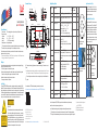
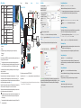
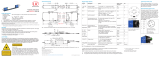
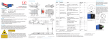
MICRO-EPSILON optoCONTROL 2520-95 Assembly Instructions
- Type
- Assembly Instructions
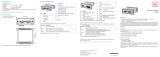
MICRO-EPSILON optoCONTROL 2520-95 is a compact, easy-to-use device designed for precise distance and position measurements. It utilizes a semiconductor laser with a wavelength of 670 nm and a maximum optical power of 2 mW, making it suitable for various industrial applications.
Key features of optoCONTROL 2520-95 include:
-
High accuracy and repeatability: The device delivers precise measurements with a resolution of 0.01 mm and a repeatability of up to 0.005 mm, ensuring reliable and consistent results.
-
Long measuring range: With a measuring range of up to 50 meters, the optoCONTROL 2520-95 can be used in applications with varying distances, making it a versatile tool for different measurement tasks.


-
 1
1
-
 2
2


MICRO-EPSILON optoCONTROL 2520-95 Assembly Instructions
- Type
- Assembly Instructions
MICRO-EPSILON optoCONTROL 2520-95 is a compact, easy-to-use device designed for precise distance and position measurements. It utilizes a semiconductor laser with a wavelength of 670 nm and a maximum optical power of 2 mW, making it suitable for various industrial applications.
Key features of optoCONTROL 2520-95 include:
-
High accuracy and repeatability: The device delivers precise measurements with a resolution of 0.01 mm and a repeatability of up to 0.005 mm, ensuring reliable and consistent results.
-
Long measuring range: With a measuring range of up to 50 meters, the optoCONTROL 2520-95 can be used in applications with varying distances, making it a versatile tool for different measurement tasks.
Ask a question and I''ll find the answer in the document
Finding information in a document is now easier with AI
Related papers
-
 MICRO-EPSILON optoCONTROL 2520-95 Assembly Instructions
-
 MICRO-EPSILON optoCONTROL 2520-46 Assembly Instructions
-
MICRO-EPSILON optoCONTROL 2520 User manual
-
 MICRO-EPSILON optoCONTROL 2520-46 Assembly Instructions
-
 MICRO-EPSILON C-Box/2A User manual
-
 MICRO-EPSILON optoCONTROL EDU190 User manual
-
 MICRO-EPSILON C-Box/2A Assembly Instructions
-
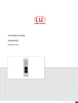 MICRO-EPSILON IF2030/PNET User guide
-
 MICRO-EPSILON optoCONTROL EDU190 Assembly Instructions
-
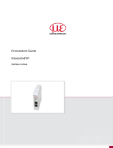 MICRO-EPSILON IF2030/ENETIP User guide


