Page is loading ...

1
VoiceLift Pro eBUS Microphone Kits • Setup Guide
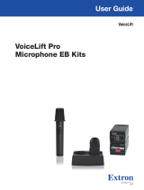
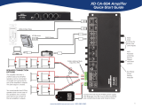
This guide provides instructions for an experienced installer to set up the Extron VLP 302 VoiceLift Compact Pendant
Microphone, the VLH 302 VoiceLift Handheld Microphone, the VLC 302 CS Charging Station, and the VLR 302EB receiver in a
system with an IP Link Control Processor.
POWER
12V
--A MAX
G
Tx Rx RTSCTS
COM 1
G
Tx Rx
COM 2
VCG
VOL
RELAYS
12 C
1 234 G
DIGITAL I/O
PWR OUT=6W
eBUS
+V +S
-S
G
LAN
IPCP PRO250
IR/S
SG
VLR 302EB
LINK
1
2
R
eBUS
LINK
COM
ERROR
ID
ERROR
VLR 302EB
+V +S -S G
eBUS
AUDIO
OUT
BUS ID
ON
1 2
3 4
5 6
POWER
12V
0.7A MAX
4
Ω
8
Ω
CLASS 2
WIRING
L
R
L
R
VCG
10V 50mA
L
MPA 152 PLUS
R
/
INPUTS
OUTPUTREMOTE
Audio
PWR LOAD
= 4.0W
Extron
VLR 302EB
Extron
IPCP Pro 250
Extron
MPA 152 PLUS
Connecting the VLC 302 Charger and Charging the Microphones
NOTE: The charging station is to be used with NiMH rechargeable batteries only.
To connect the charger and charge the microphone(s):
1. Connect the 5 VDC, 2.6 A wall charger to a 110-130 VAC (US) or a
100-240 VAC (international), 50-60 Hz power source.
2. Connect the USB mini plug end of the adapter to the USB mini jack located
on the back of the VLC 302 (
2
).
NOTE: The charger can also be powered by a USB source using a mini
USB cable.
3. Unscrew and remove the microphone battery cover to install the battery.
Insert the battery, aligning the + and – poles as indicated inside the
compartment.
VLP 302
(Cover Removed)
VLH 302
(Cover Removed)
+
+
_
BATTERY
BATTERY
4. Insert the microphone into one of the charger slots (
4
). The microphone
LED lights red when charging and turns green when the microphone is
fully charged.
NOTE: Microphones can be left to charge for extended periods.
CAUTION: Do not replace the batteries with an incorrect type. Use only
rechargeable NiMH batteries specified or provided by Extron, or alkaline
batteries.
ATTENTION:
• Do not attempt to charge alkaline batteries.
• Be sure to replace the battery with the correct type and to dispose of
used batteries appropriately.
LED
44
11
22
LED
44
11
22

2
Installing the VLR 302EB Receiver
The VLR 302EB Receiver outputs audio signals transmitted from the microphones as one balanced mono line level signal.
Connect and set up the VLR 302EB as shown below.
NOTE: For mounting instructions, see the VoiceLift Pro eBUS User Guide.
A
eBUS connector - Connect an Extron IPCP Pro control processor to this four-pole captive
screw connector.
NOTE: The VLR 302EB requires an eBUS connection with an Extron IPCP Pro
processor for power and communication. If not connected to an IPCP Pro processor,
the VLR 302EB will not output audio.
Extron STP20-2/1000 or STP20-2P/1000 cable is recommended for eBUS connections.
Connect a 4-pole captive screw connector to each end of the cable, wiring both ends as
shown below.
Ground
+ Signal
+12 VDC
-
Signal
Drain Wires (2)
G
-
S
+S
+V
Black
White
Green
Red
VLR 302EB
+V +S -S G
eBUS
AUDIO
OUT
BUS ID
ON
1 2
3 4
5 6
PWR LOAD
= 4.0W
AB
C
Setting eBUS IDs
Up to eight eBUS devices can be connected to one control processor. Each device connected to the same IPCP Pro control
processor must have a unique BUS ID, which is set using the BUS ID DIP switches (see
B
, above).
NOTE: If two or more devices have the same eBUS ID, address conicts may cause one or more of the devices to not be
recognized by the IPCPPro control processor.
Various combinations of the six DIP switches (being set to On or Off) provide 64 eBUS IDs (see the VoiceLift Pro eBUS User Guide
for a table showing the DIP switch settings for all 64 possible addresses). Default address is 26.
BUS ID
ON
1 2
3 4
5 6
Dip Switch
Position
Decimal
Off
1
2
5
=32
2
On
2
4
=16
5
On
2
1
=2
4
Off
2
2
=4
3
On
2
3
=8
6
Off
2
0
=1
0 + 16 + 8 + 0 + 2 + 0 = 26
NOTES:
• Any address can be used except address 0 (binary: 000000), which is reserved as the address of the controller.
• Switch 1 (on the left) is the highest value (32, the most signicant bit).
• Switch 6 (on the right) is the lowest value (1, the least signicant bit).
• Up = On = 1, Down = Off = 0
B
DIP switches - Use these DIP switches to assign an eBUS ID to the devices connected to the IP Link control processor.
Each device connected to the control processor must have a unique eBUS ID (see “Setting eBUS IDs” below).
C
Mono audio output - Connect a balanced or unbalanced audio device (such as an amplier or mixer) to this 3-pole captive
screw connector. Wire the connector as shown below:
3-pole Mono Audio OUTPUT Wiring
Unbalanced Output
Tip
Sleeve
NO Ground Here
Balanced Output
Tip
Sleev
e
Ring
ATTENTION: For unbalanced audio outputs, connect the sleeves to the ground contact. DO NOT connect the sleeves
to the negative (-) contacts.

3
VLH 302 Handheld Microphone
To operate the VLH 302:
1. Verify that the battery is installed and fully charged.
2. Turn the microphone on by sliding the power switch up.
NOTE: Each VoiceLift kit includes a VLR 302EB receiver and
microphones that have already been paired. Follow the steps on
the next page to pair the microphone if necessary.
3. Speak in a normal tone of voice, adjusting the volume level as needed.
4. When nished, return the microphone to the charging station.
Status
LED
Power
Switch
5. Turn on the microphone by holding the power button (
5
) for three seconds.
One of the LINK LEDs on the VLR 302EB receiver will illuminate to indicate
that connection has been established.
NOTE: Each VoiceLift kit includes a VLR 302EB receiver and
microphones that have already been paired. Follow the steps on the
next page to pair the microphones if necessary.
6. Speak in a normal tone of voice, adjusting the volume level as needed (
6
).
7. When nished, return the microphone to the charging station.
Status
LED
5
6
Setting up the Microphones
VLP 302 Pendant Microphone
To set up the VLP 302:
1. Verify that the battery is installed and fully charged.
2. Set the microphone(s) for either Teacher or Student mode using the
DIP switch, accessible from beneath the battery cover (see
2
at
right):
• In Teacher mode (default), all microphone features are fully
functional. Set the dip switch to the OFF (down) position to
enable “teacher” mode.
• In Student mode, all buttons are disabled except for power. Set
the dip switch to the ON (up) position to enable “student” mode.
3. Apply the appropriate label (provided) to identify the microphone
(see
3
at right).
4. To wear as a pendant microphone:
a. Push the lanyard into the guides on the lanyard lock.
b. Open the microphone clip.
c. Slide up the lanyard lock under the clip, then release the clip.
d. Place the lanyard around
your neck. Adjust the
microphone by sliding it up
so it rests approximately
6 inches (15.2 cm) below
your chin.
2
3
TEACHER
c
b
Press to
open clip
Lanyard
Lock
a
~ 6
”
VLH 302
(Cover Removed)
+
V
olume
Buttons

4
B
A
C
Pairing Microphones with the VLR 302EB Receiver
Each VoiceLift kit includes microphones and a VLR 302EB receiver that have already been paired. If needed, follow the
steps below to pair microphones with a receiver.
Clear previously paired microphones from the VLR receiver
1. Ensure that the microphones are placed in the VLC 302 CS charger or powered off.
2. Press and hold the Reset button (
A
) until the Power LED ashes once (approx. 3
seconds), then immediately release and momentarily press the Reset button again (for
<1 second) within 1 second.
Both LINK LEDs (
B
) blink to conrm pairing has been cleared.
Pair new microphones
Follow these steps to pair each microphone, one at a time, to the VLR 302EB receiver.
NOTE: All paired microphones should be fully charged and turned off before pairing new microphones.
1. Press and hold the LINK button on the VLR 302EB receiver (see
C
in the image above) for 4 seconds to start pairing mode.
If LINK slots are available, one of the LINK LEDs (see
B
in the image above) blinks to indicate that pairing mode has started.
NOTES:
• Once initiated, the VLR receiver pairing mode is enabled for 30 seconds, and users must set the microphones to
pairing mode (see step 2) within the allocated time. Repeat the process if the 30 second pairing window time has
been exceeded or if pairing was not successful.
• Receiver Pairing/Discovery mode can also be enabled remotely from a control system that has been congured to
control the VLR receiver. See the VoiceLift Pro eBUS User Guide for details.
2. Follow the steps below for your microphone model:
• VLP 302: Ensure that the VLP 302 microphone is powered off.
NOTE: The VLP microphone must be in “TEACHER”
mode in order to pair.
While powered off, press and hold the Function (
A
) and
Power (
B
) buttons simultaneously for 4 seconds until the
status LED blinks red and green, indicating pairing mode has
started.
• VLH 302: Power the VLH 302 handheld microphone on.
Press and hold the LINK button, located beneath the battery
cover (see
C
at right), for 4 seconds until the status LED
blinks red and green, indicating pairing mode has started.
NOTE: The receiver assigns the microphone to the rst available LINK slot. The LINK LED on the
VLR receiver will illuminate solid green when the microphone has been paired successfully.
3. Once a microphone has been paired, test the audio by speaking into the microphone, then power the
microphone off. Repeat from step 1 for each microphone being paired.
4. After pairing the microphones, verify that they have been set up properly as shown in the previous section, Setting up the
Microphones, on the previous page.
VLR 302EB
LINK
1
2
R
eBUS
LINK
COM
ERROR
ID
ERROR
B C
A
68-3268-50
Rev. A
02 20
© 2020 Extron Electronics — All rights reserved. www.extron.com
All trademarks mentioned are the property of their respective owners.
Worldwide Headquarters: Extron USA West, 1025 E. Ball Road, Anaheim, CA 92805, 800.633.9876
For information on safety guidelines, regulatory compliances, EMI/EMF compatibility, accessibility, and related topics, see the
Extron Safety and Regulatory Compliance Guide on the Extron website.
/
