5
Pairing with the VLR 302 Receiver
Each VoiceLift kit includes VLP 302/VLH 302 microphones and VLR 302 receivers that have already been paired. If needed, follow
the steps below to pair microphones with a receiver.
Verify which Microphones are Paired
1. Ensure that the microphones are fully charged. Power each microphone on, one at a
time, to determine if the microphones are paired to the VLR 302 receiver.
NOTES:
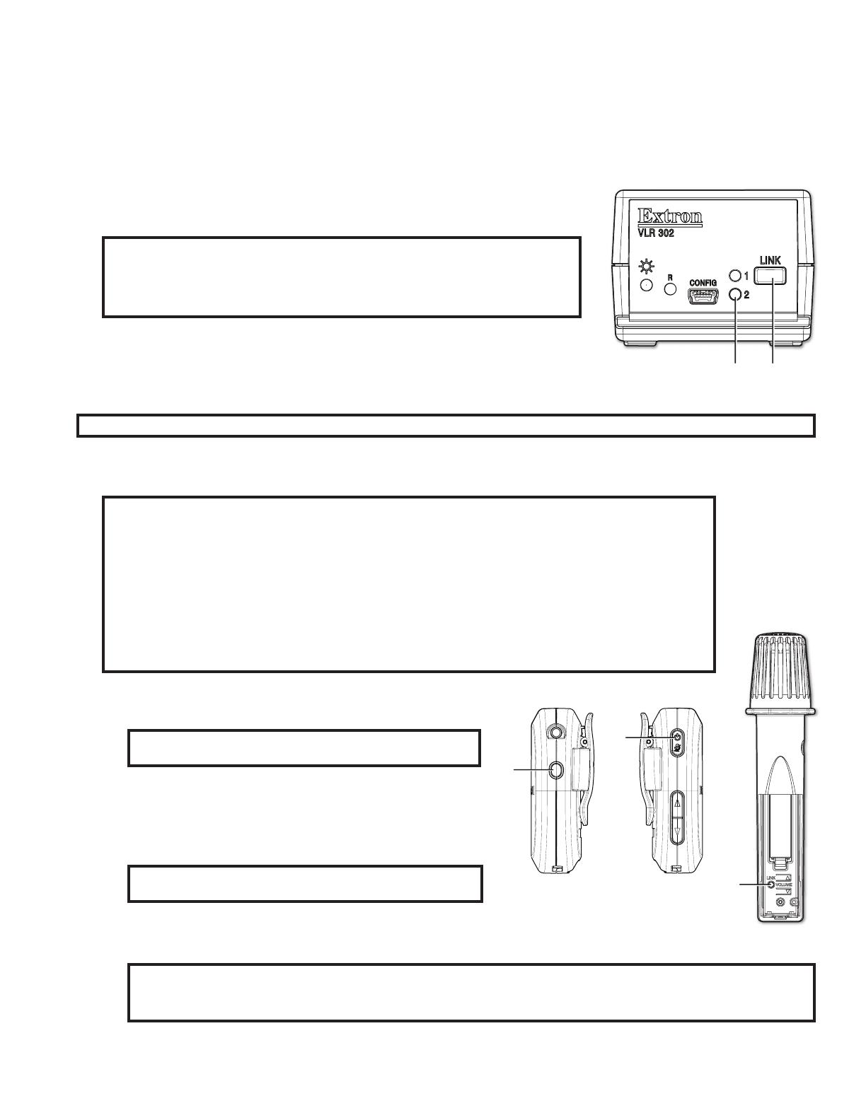
• As each microphone is powered on, one of the VLR link slot LEDs (see A
at right) illuminates if the microphone is paired.
• Only one microphone can be paired to each LINK slot on the VLR receiver.
2. Once you have determined which microphones are paired, turn them o.
Pair New Microphones
Follow these steps to pair each microphone to the VLR 302 receiver.
NOTE: All paired microphones must be turned o before pairing new microphones.
1. Press and hold the LINK button on the VLR 302 receiver (see B in the image above) for 4 seconds to start pairing mode.
If LINK slots are available, one of the LINK LEDs blinks to indicate that pairing mode has started.
NOTES:
• Once initiated, pairing mode is enabled for 30 seconds. Users must repeat the process if they have
exceeded the 30 second pairing window or if pairing was not successful.
• Receiver Pairing/Discovery mode can also be enabled remotely using Product Configuration
Software (PCS) or SIS comands (see the VoiceLift Pro Microphone Kits User Guide). Commands
can be sent to the receiver through direct USB connection using a PVCA 452 connection or PVS
switcher connection.
• If adding a new microphone to the system (or replacing a current microphone), and both Link slots
are currently assigned, reset the VLR 302 to clear the pair history (see Clearing Pair History on
the next page).
2. Follow the steps below for your microphone model:
• For the VLP 302: Ensure that the microphone is powered off.
NOTE: The VLP microphone must be in “TEACHER” (o)
mode in order to pair.
Then, press and hold the POWER and FUNCTION buttons (see
A and B at right) simultaneously for 4 seconds until the status
LED blinks red and green, indicating pairing mode has started.
• For the VLH 302: Ensure that the microphone is powered on.
NOTE: The VLH microphone must be in “STUDENT” (on)
mode in order to pair.
Then, press and hold the LINK button, located beneath the battery cover (see C at right), for 4 seconds.
The microphone status LED changes from solid amber to alternating red and green, indicating that pairing
mode has started.
NOTES:
• The receiver assigns the microphone to the first available LINK slot.
• If the microphone is paired successfully, one of the LINK LEDs on the VLR receiver lights solid green.
3. After pairing the microphones, verify that they have been set up properly as shown in the previous section, Setting up the
Microphones on page 2. Repeat steps 1-3 for each microphone being paired.
B
A


