Page is loading ...

Page | 1
MimioClarity
TM
Technical
User’s Guide
The MimioClarity is a standalone or networked
classroom audio distribution system that
shares teacher, student, and lesson media throughout the classroom. It is a multi-room, multi-microphone
system. The MimioClarity system will work with up to four (4) microphones in any combination of teacher
or student microphones. MimioClarity will also work with up to four (4) different amplifiers.
Key Terms
• Paired – when the microphone is paired with the amplifier, the two devices have been
“introduced” and have agreed to pass data sound between them
• Connected – once the microphone has been paired it must be connected to the amplifier
in the room where the sound is to be distributed, otherwise the microphone will broadcast
audio to each room it is paired with (up to 4 rooms can be paired with each microphone)
• Press – press the button and release
• Press and Hold – press the button and hold the button down

Page | 2
Table of Contents
Overview: MimioClarity Teacher Microphone ........................................................................................... 4
Overview: MimioClarity Student Microphone ............................................................................................ 7
Pairing and Connecting the Teacher Microphone .................................................................................. 9
Pairing the Teacher Microphone .......................................................................................................... 9
Connecting the Teacher Microphone ................................................................................................. 10
Resetting Amplifier & Clearing all Paired Mics: ........................................................................................ 10
Using the Teacher Microphone.............................................................................................................. 10
Adjusting the Volume on the Teacher Microphone .............................................................................. 10
Muting the Teacher Microphone ........................................................................................................ 11
External Microphone ......................................................................................................................... 11
External Device Line Input.................................................................................................................. 11
Student Microphone ............................................................................................................................. 12
Pairing the Student Microphone ........................................................................................................ 12
Connecting the Student Microphone.................................................................................................. 12
Using the Student Microphone .......................................................................................................... 12
Student Microphone Care ................................................................................................................. 12
Clarity Amplifier ..................................................................................................................................... 13
Amplifier Labeled ............................................................................................................................... 13
Wiring Clarity ........................................................................................................................................ 15
Wiring Diagrams ................................................................................................................................ 15
3.5mm Stereo Wiring Diagram ....................................................................................................... 16
RJ45 Input Wiring Diagram (Inputs 4, 5) ......................................................................................... 16
RJ45 Output Wiring Diagram (Output 1) ......................................................................................... 16
RJ45 MIC / GPIO 1-3 .................................................................................................................... 16
Bluetooth .............................................................................................................................................. 17
Clarity Accounts ................................................................................................................................... 18
Accessing the Clarity Amplifier Interface ................................................................................................ 18
Accessing via the Network ................................................................................................................ 19
Accessing via the USB cable ............................................................................................................. 19
Logging into the Clarity “User” Account ................................................................................................. 19
Accessing the Clarity Amplifier “IT” Account........................................................................................... 21

Page | 3
Input Page (User and IT Accounts) ........................................................................................................ 22
Text to Speech ..................................................................................................................................... 28
Network Page – Wired & DHCP ......................................................................................................... 29
Network Page – USB ............................................................................................................................ 29
Network Page – DNS ............................................................................................................................ 30
Network Page – NTP ............................................................................................................................ 30
Setting the Time Zone ....................................................................................................................... 31
Setting a Time Server Pool Address ................................................................................................... 31
SIP Page (Registering)........................................................................................................................... 32
Maintenance Page ................................................................................................................................ 32
Other Page ........................................................................................................................................... 33
Users Page ........................................................................................................................................... 34

Page | 4
Overview: MimioClarity Teacher Microphone
Easy to use and lightweight, the microphone has 10 hours of battery life and is held around the teacher’s
neck on a break-away lanyard. Teacher microphone can be used as a clicker to easily navigate slides that
are being shared at the front of the class. The teacher mic has a simple two-button volume control to
ensure that each word is heard by every student. Best of all, Boxlight technology does not rely upon a line
of sight, like IR receivers. MimioClarity RF will not interfere with Wi-Fi or Bluetooth frequencies.
Teacher Microphone
Frequency
DECT 1.9GHz
(Does not interfere with Bluetooth or Wi-Fi)
Wireless Range
Up to 100 feet.
Microphone Type
Omnidirectional
Frequency Response
100 hz – 8khz
Auxiliary Mic Input
1 x 3.5 mm mic level input
Auxiliary Line Input
1 x 3.5 mm line level input
Battery
Lithium-ion (rechargeable)
Talk Time
10 hours
Charge Time
2 hours
Charging Method
USB C (can be used while being charged)

Page | 5
Controls and Integration
Controls
•
On/Off
• Teacher mic mute button is blue red when muted
and blue while charging
• Teacher mic volume up and down control; concave
button distinguishes between volume up and down
• Pairing button: Single button to connect mic with amp in
the room with near field bonding technology
• Programmable left/right button to PC connected to amp
via USB-A (Default: Page up/page down)
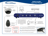
Inputs, Output, and Buttons
①
Omnidirectional Mic Picks up sound with equal gain from all sides or directions
②
On/Off Button
Power the microphone on and off. Buttons are backlit
when on
③
Pairing/Connecting
Uses near field handshake to simply bond the
microphones with a single button for connecting
④
Mic Input Side Button: 1 x 3.5 mm mic input
⑤
Audio Line In Side Button: 1 x 3.5 mm stereo line input
⑥
Volume Up
Turns the volume of the microphone up to next of six
presets, 2 up and 3 down.

Page | 6
⑦
Page Up/Alert
Side Button: Page up to connected PC (like a presenter
clicker)
⑧
Page Down/Alert
Side Button: Page down to connected PC (like a
presenter clicker)
⑨
Volume Down
Turns the volume of the microphone down to next of six
presets 2 up and 3 down.
⑩
Mute Button Mutes the teacher microphone
⑪
USB-C
Charges the microphone in approximately 2 hours. The
microphone can be used while charging.
Dimensions and Weight
Overall Dimensions
(W x H x D)
3.5” x 1.754” x .75” (99mm x 46mm x 19mm)
Net Weight
2.2 oz. (62g)
Environmental
Storage Temperature
Storage: -40 to 158°F (-40 to +70°C)/10–90% non-
condensing
Storage Humidity
Storage: -40 to 158°F (-40 to +70°C)/10–90% non-
condensing
Battery
Lithium-ion (rechargeable)
Certification
FCC, CE, UL
Material safety data available on request
Accessories
Replacement batteries
6ft USB C cable
Replacement Lanyards

Page | 7
Overview: MimioClarity Student Microphone
Every student’s voice should heard. It’s critical for student engagement that they too have a microphone
to participate in lessons. The mic is designed to withstand the rigors of a classroom while simple to use;
no manual is required (albeit one is provided). Student microphone can also be used to distribute media
through the 3.5 Audio Line Input as well as capture group conversations when toggled on.
Student Microphone
Frequency
DECT 1.9 GHz
(Does not interfere with Bluetooth or Wi-Fi)
Wireless Range
Up to 200 feet
Microphone Type
Omnidirectional
Frequency Response
100 hz – 8 khz
Auxiliary Line Input
1 x 3.5 mm line level input
Battery
Lithium-ion (rechargeable)
Talk Time
10 hours
Charge Time
2 hours
Charging Method
USB C (can be used while being charged)

Page | 8
Controls and Integration
Controls
• On/off button
• Toggle-to-talk switch
• Push-to-talk button
• Pairing button: Single button to connect mic with amp
in the room using the Boxlight near field bonding
technology
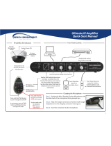
Inputs, Output, and Buttons
①
On/Off Button
Power the microphone on and off. Buttons are backlit
when on.
②
Pairing/Connecting
Uses near field handshake to simply bond the
microphones with a single button
③
Push-to-Talk Button
Push down to turn on microphone to capture voice like a
CB radio. Button is blue while charging
④
Toggle-to-Talk Switch Switch to activate the microphone being continuously on
⑤
Audio Line In 1 x 3.5 mm stereo line input
⑥
USB-C
Charges the microphone in approximately 2 hours. The
microphone can be used while charging.
⑦
Omnidirectional Mic Picks up sound with equal gain from all sides or directions
Dimensions and Weight
Overall Dimensions
(W x H x D)
1.25” x 8.5” x 1.25” (31.75mm x 216mm x 32mm)
Net Weight
3.9 oz. (110g.)

Page | 9
Environmental
Storage Temperature
Storage: -40 to 158°F / 10–90% non-condensing
Storage Humidity
Storage: -40 to 158°F / 10–90% non-condensing
Battery
Lithium-ion (rechargeable)
Certification
FCC, CE, UL
Material safety data available on request
Accessories
Replacement batteries
Pairing and Connecting the Teacher Microphone
Pairing the Teacher Microphone
1. Press the Pairing Button on the Clarity amplifier.
2. Press the Power Button on the teacher microphone placing the microphone in the “ON”
position. The button will illuminate green.
3. Press and hold the Pair/Connect button until it begins blinking green. After
roughly 30 seconds the light will stop blinking.
4. The microphone is now paired, but the Pair/Connect button will remain red
.
NOTE: Pairing is required only once!
Pairing Button

Page | 10
Connecting the Teacher Microphone
1. Stand between 5-10 feet from the MimioClarity Amplifier.
2. Press the Power Button placing the microphone in the “ON”
position. Button will be green
3. Wait a moment for the Pair/Connect button to turn red.
4. Press the Pair/Connect button. The button will turn green once the
microphone is connected to the amplifier.
NOTE: The Microphone will need to be connected each time it is
powered on.
Resetting Amplifier & Clearing all Paired
Mics:
To clear all microphones paired to a receiver you will need to do a reset.
To Reset the amplifier:
• Hold the power button down on the amplifier; this could be up to 15 seconds or more
• Once the amplifier powers off, wait 2 seconds
• Press the power button again until it blinks green then turns solid red
Once you have reset the amplifier, all microphones will have to be paired again and reconnected.
Using the Teacher Microphone
1. Adjust the lanyard so the microphone is 3-4 inches below your chin.
2. Turn the microphone on.
3. Press the pair button one time.
4. Talk in a normal tone.
5. When finished, turn the microphone off and charge.
Adjusting the Volume on the Teacher Microphone
The Clarity Teacher Microphone is simple to operate and is designed so that the user does not raise
the volume too high or lower the volume so that the voice isn’t heard. The microphone has six (6)
presets which can be adjusted by pressing the up and down arrows.
Power On/Off
Pair/Connect

Page | 11
• To increase the volume, press the up-volume button ; the
volume can be adjusted upward two (2) positions from the
base level.
• To decrease the volume, press the down-volume button ;
the volume can be adjusted down three (3) positions from the
base level.
Muting the Teacher Microphone
To have a private conversation with a student or group, the teacher can press
the Mute button. Once pressed, it will illuminate red and stay red until it is
pressed again to unmute. The mute button will also be illuminated blue while
charging.
• To mute the microphone, press the mute button one time.
• To unmute the microphone, press the mute button one time.
NOTE: Covering the microphone will not mute the microphone, and neither will stepping outside of
your room!
External Microphone
An external microphone may be desired. Most non-powered microphones with a 3.5 connector may
be utilized.
NOTE: When an external microphone is plugged into the teacher microphone, the on-board
microphone will be disabled.
External Device Line Input
An MP3 player or other type of audio device may be plugged into the line
line input on the teacher microphone. The audio from the external device will
broadcast through the MimioClarity amplifier.
Volume Up
Volume Down
Mute
MIC
LINE

Page | 12
Student Microphone
Pairing the Student Microphone
1. Press the Pairing Button on the MimioClarity amplifier.
2. Press the Power Button placing the microphone in the “On”
position. This button will illuminate green.
3. Press and hold the Pair/Connect Button on the student microphone until it begins blinking
green. After roughly 30 seconds the light will stop blinking.
4. The microphone is now paired. However, the Pair/Connect button will remain red.
NOTE: Pairing is required only once.
Connecting the Student Microphone
1. Stand between 5 and 10 feet from the MimioClarity amplifier.
2. Press the Power Button placing the microphone in the “On”
position. This button will illuminate green.
3. Wait a moment for the Pair/Connect Button to turn red.
4. Press the Pair/Connect button . The button will turn green once the
microphone is connected to the amplifier.
NOTE: The microphone will need to be connected each time it is powered on.
Using the Student Microphone
The MimioClarity Student Microphone is simple to operate and is powered by two methods:
• Press the power button to turn the microphone on and press the pair button to connect.
o Press and hold the “Push to talk”
o Slide the “Toggle to Talk” button upward. The mic is now on constantly.
Student Microphone Care
• Charge the microphone at the end of each day by inserting the USB charging cable into the
microphone USB charging port.
• While durable, the microphone is not designed to be dropped, kicked, tossed, thrown, etc.
The microphone is designed to be worn and set gently down when not in use.
Pairing Button
Power On/Off
Pair/Connect

Page | 13
• The microphone may be cleaned with a damp cotton cloth. Do not use harsh chemicals or
abrasives on the microphone.
Clarity Amplifier
The Clarity amplifier has been designed as a “Set and
Forget” headless device. In other words, once the device
has been installed and audio levels set by a qualified
installer the device never needs adjustments.
Amplifier Labeled
Inputs, Output, Connections, and Buttons
①
Ethernet 10/100 Mbps POE
②
USB C Interface 1 x USB C (Bottom side: Interface with local computer)
③
Control I/O 1 x 3 Pin Phoenix Connector, RS 232
④
Audio Line In 3 - Line In 3.5
⑤
Audio Line In With
Control
2 x RJ 45-line level audio input, RS 232, Power 5/24
DC output option
⑥
Audio Line In With
Control
1 x RJ 45-line level audio output, RS 232, Power 5/24
DC output option
⑦
Audio Line Out 1 x 3.5 mm line level output
⑧
Power Input External 24 VDC

Page | 14
⑨
Reset Button Reset to factory settings
⑩
Status Lights Green = working; red = fault
⑪
GPIO Microphone Input 1 x RJ 45 GPIO 1, GPIO 2, GPIO 3
⑫
Speaker Output and PA
Connector
Phoenix connector speaker A, B. Connect to building
paging system mutes all amplifier inputs in the event
of a building page.
Inputs, Output, Connections, and Buttons Continued
⑬
ALD Button
Uses near field handshake (future Product
development available 2021)
⑭
Paring Button Bond the microphones
⑮
Bluetooth & Wifi Dongle
Slot
USB for BT and Wifi Accessories

Page | 15
Wiring Clarity
Wiring Diagrams
Speakers – Connect the Clarity speakers, (two speakers per channel), parallel to speaker ports A and B.
Note: Clarity does not broadcast audio in Stereo.
Page Mute – Connect the building’s paging speaker to the Page Mute connector on the Clarity amplifier.
(When the building’s paging speakers receive audio, the Clarity amplifier will mute all audio. When the
building’s paging speakers no longer receive audio, the Clarity amplifier will no longer mute audio.)
3.5 Input(s) – Connect the Boxlight Interactive Flat Panel to Input 1 on the Clarity amplifier. Connect other
audio devices to inputs 2 and 3.
Network - For network control of the Clarity amplifier connect the network port to the building’s IP
network.

Page | 16
3.5mm Stereo Wiring Diagram
This diagram applies to Inputs 1,2 and 3
as well as Output 2.
RJ45 Input Wiring Diagram (Inputs 4, 5)
This diagram applies to Inputs 4 and 5.
RJ45 Output Wiring Diagram (Output 1)
This diagram applies to Output 1.
RJ45 MIC / GPIO 1-3
This diagram applies to wired MIC and GPIO’s 1 – 3.

Page | 17
Bluetooth
Using the optional Clarity Bluetooth dongle, your Clarity amplifier may pair with your IOS or Android device
allowing audio from your device to broadcast to the Clarity amplifier. By default, the Clarity amplifier
requires the use of a pairing code. This feature may be disabled by removing the check in the “Use pairing
code” check box.
The following instructions demonstrate pairing a Bluetooth device with the pairing code required.
1. Log into the Clarity amplifier and navigate to the Bluetooth page.
2. From your IOS (shown) or Android device,
search for the Clarity amplifier.
3. Verify the pairing code matches the pairing
code on the Clarity Bluetooth page.
4. Press the pair link on your device.

Page | 18
5. Press the “Yes” button on the Clarity Bluetooth page.
6. The Clarity amplifier will announce the Bluetooth device is connected.
7. You may now broadcast audio from your Bluetooth device through the Clarity amplifier.
Note: Volume is ultimately controlled by the input level of Bluetooth device.
Clarity Accounts
The Clarity amplifier contains two account types:
1. “user” account – This account is designed for the “End User” who would like to make minor
adjustment to the audio input, output or digital equalizer settings as well as connect a bluetooth
device as a source audio input.
2. “IT” account – This account is designed for the staff members responsible for the setup and
maintenance operations related to the Clarity amplifier.
Accessing the Clarity Amplifier Interface
The Clarity Amplifier is accessed via your favorite web browser (Chrome Recommended) using the USB-C
port or via the network. However, to access the amplifier you must know the IP address of the device. By
default, the USB IP address is pre-set. Accessing the amplifier over the network will require the use of the
speakers or a network scanner, e.g. Advanced IP Scanner.
From the factory, the Clarity amplifier is set to announce (through the speakers and/or 3.5 audio output)
the IP address of the wired, wireless, and USB connections when the device is booted.

Page | 19
Accessing via the Network
These instructions assume you are in the same room as the amplifier with speakers, and/or the
headphones are connected to the amplifier.
1. Press the reset button. (See Clarity Connections
)
2. Listen for the amplifier to announce the IP address of the wired network.
3. Type the IP address in your favorite web browser and press enter.
Accessing via the USB cable
These instructions assume you are in the same room as the amplifier with the USB cable connected to the
amplifier and your computer.
1. Using a USB C cable, connect the amplifier to your computer.
2. Open your favorite web browser and type, 192.168.123.1 and press enter.
You are now ready to login. See Logging into the Clarity User Interface.
Logging into the Clarity “User” Account
The Clarity Amplifier is accessed via
your favorite web browser (Chrome
Recommended) using the USB-C port
or via the network.
The following instructions will walk the
user through accessing the amplifier
using both methods.

Page | 20
USB-C
1. Using the USB-C port adjacent to the Network port, connect the amplifier to the computer.
2. Open your favorite web browser and type the following IP address: 192.168.123.1
Network
3. Obtain the IP address of the amplifier. (See options for obtaining the IP address)
4. Open your favorite web browser and type the network IP address.
5. In the username field type (lowercase) “user”.
6. In the password field type “12345”.
7. Click the Login button.
8. The page will load the Input page.
From this page, the user may adjust inputs, outputs, and digital “EQ”.
/