
AN 987: Static Update Partial
Reconfiguration Tutorial
for Intel® Agilex™ F-Series FPGA Development
Board
Updated for Intel® Quartus® Prime Design Suite: 22.3
Answers to Top FAQs:
QWhat is static update partial reconfiguration
AStatic Update Partial Reconfiguration on page 3
QWhat do I need for this tutorial?
ATutorial Requirements on page 3
QWhere can I get the reference design?
ADownload Reference Design Files on page 5
QHow do I create an SUPR design?
AReference Design Walkthrough on page 6
QWhat is a PR persona?
ADefine Personas on page 10
QHow do I change SUPR logic?
AChange the SUPR Logic on page 16
QHow do I program the board?
AProgram the Board on page 18
QWhat are the PR known issues and limitations?
AIntel FPGA Support Forums: PR
QDo you have training on PR?
AIntel FPGA Technical Training Catalog
Online Version
Send Feedback AN-987
ID: 749443
Version: 2022.10.24

Contents
1. Static Update Partial Reconfiguration Tutorial for Intel® Agilex™ F-Series FPGA
Development Board................................................................................................... 3
1.1. Tutorial Requirements............................................................................................ 3
1.2. Reference Design Overview.....................................................................................4
1.3. Static Update Region Overview................................................................................4
1.4. Download Reference Design Files............................................................................. 5
1.5. Reference Design Walkthrough................................................................................ 6
1.5.1. Step 1: Getting Started.............................................................................. 7
1.5.2. Step 2: Create Design Partitions.................................................................. 7
1.5.3. Step 3: Allocate Placement and Routing Regions............................................ 8
1.5.4. Step 4: Define Personas............................................................................10
1.5.5. Step 5: Create Revisions...........................................................................11
1.5.6. Step 6: Compile the Base Revision............................................................. 13
1.5.7. Step 7: Set Up PR Implementation Revisions............................................... 14
1.5.8. Step 8: Change the SUPR Logic................................................................ 16
1.5.9. Step 9: Program the Board........................................................................18
1.5.10. Modifying the SUPR Partition....................................................................19
1.6. Document Revision History of AN 987: Static Update Partial Reconfiguration
Tutorial Revision History.....................................................................................20
Contents
AN 987: Static Update Partial Reconfiguration Tutorial: for Intel Agilex F-
Series FPGA Development Board Send Feedback
2

1. Static Update Partial Reconfiguration Tutorial for Intel®
Agilex™ F-Series FPGA Development Board
This application note demonstrates static update partial reconfiguration (SUPR) on the
Intel® Agilex™ F-Series FPGA Development Board.
Partial reconfiguration (PR) allows you to reconfigure a portion of an Intel FPGA
dynamically, while the remaining FPGA continues to operate. PR implements multiple
personas in a particular region in your design, without impacting operation in areas
outside this region. This methodology provides the following advantages in systems in
which multiple functions time-share the same FPGA resources:
• Allows run-time reconfiguration
• Increases design scalability
• Reduces system down-time
• Supports dynamic time-multiplexing functions in the design
• Lowers cost and power consumption by efficient use of board space
What is Static Update Partial Reconfiguration?
In traditional PR, any change to the static region requires recompilation of every
persona. However, with SUPR you can define a specialized region that allows change,
without requiring the recompilation of personas. This technique is useful for a portion
of a design that you may possibly want to change for risk mitigation, but that never
requires runtime reconfiguration.
1.1. Tutorial Requirements
This tutorial requires the following:
• Basic familiarity with the Intel Quartus® Prime Pro Edition FPGA implementation
flow and project files.
• Installation of Intel Quartus Prime Pro Edition version 22.3, with Intel Agilex
device support.
• For FPGA implementation, a JTAG connection with the Intel Agilex F-Series FPGA
development board on the bench.
•Download Reference Design Files.
Related Information
•Partial Reconfiguration User Guide
•Partial Reconfiguration Tutorials
•Partial Reconfiguration Online Training
749443 | 2022.10.24
Send Feedback
Intel Corporation. All rights reserved. Intel, the Intel logo, and other Intel marks are trademarks of Intel
Corporation or its subsidiaries. Intel warrants performance of its FPGA and semiconductor products to current
specifications in accordance with Intel's standard warranty, but reserves the right to make changes to any
products and services at any time without notice. Intel assumes no responsibility or liability arising out of the
application or use of any information, product, or service described herein except as expressly agreed to in
writing by Intel. Intel customers are advised to obtain the latest version of device specifications before relying
on any published information and before placing orders for products or services.
*Other names and brands may be claimed as the property of others.
ISO
9001:2015
Registered

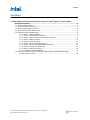
1.2. Reference Design Overview
This reference design consists of one, 32-bit counter. At the board level, the design
connects the clock to a 50MHz source, and then connects the output to four LEDs on
the board. Selecting the output from the counter bits, in a specific sequence, causes
the LEDs to blink at a specific frequency. The top_counter module is the SUPR
region.
Figure 1. Flat Reference Design
D
CLK
D
CLK
D
CLK
D
CLK
led_three_on
led_two_on
led_zero_on
led_one_on
Q
Q
Q
Q
D
CLK
u_blinking_led
count_d[31..0]
u_top_counter
clock
clock
Q
count_d[31..0]
led_one_on
led_three_on
led_two_oncount_d[31..0]
clock
SUPR Region
PR Region
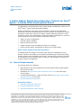
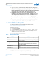
1.3. Static Update Region Overview
The following figure shows the block diagram for a PR design that includes a SUPR
region. Block A is the Top static region. Block B is the SUPR region. Block C is the PR
partition.
Figure 2. PR Design with SUPR Region
D
CLK Q
D
CLK Q
<n>
<n>
<n>
<n>
<n>
A: Top (Static)
D
CLK Q
B: SUPR C: PR Partition
Reg1
Reg2
Reg<n>
<n>
1. Static Update Partial Reconfiguration Tutorial for Intel® Agilex™ F-Series FPGA Development
Board
749443 | 2022.10.24
AN 987: Static Update Partial Reconfiguration Tutorial: for Intel Agilex F-
Series FPGA Development Board Send Feedback
4

•A Top Static Region—contains design logic that does not change. Changing this
region requires recompilation of all associated personas. The static region includes
the portion of the design that does not change for any persona. This region can
include periphery and core device resources. You must register all communication
between the SUPR and PR partitions in the static region. This requirement helps to
ensure timing closure for any personas, with respect to the static region.
•B SUPR Region—contains core-only logic that may possibly change for risk
mitigation, but never requires runtime reconfiguration. The SUPR region has the
same requirements and restrictions as the PR partition. The SUPR partition can
contain only core resources. Therefore, the SUPR partition must be a child
partition of the top-level root partition that contains the design periphery and
clocks. Changing the SUPR region produces a SRAM Object File (.sof) that is
compatible with all existing compiled Raw Binary File (.rbf) files for PR partition
C.
•C PR Partition—contains arbitrary logic that you can reprogram at runtime with
any design logic that fits and achieves timing closure during compilation.
1.4. Download Reference Design Files
The partial reconfiguration tutorial is available in the following location:
https://github.com/intel/fpga-partial-reconfig
To download the tutorial:
1. Click Clone or download.
2. Click Download ZIP. Unzip the fpga-partial-reconfig-master.zip file.
3. Navigate to the tutorials/agilex_pcie_devkit_blinking_led_supr
subfolder to access the reference design.
The flat folder consists of the following files:
Table 1. Reference Design Files
File Name Description
top.sv Top-level file containing the flat implementation of the design. This module
instantiates the blinking_led sub-partition and the top_counter module.
top_counter.sv Top-level 32-bit counter that controls LED[1] directly. The registered output
of the counter controls LED[0], and also powers LED[2] and LED[3] via the
blinking_led module.
blinking_led.sdc Defines the timing constraints for the project.
blinking_led.sv In this tutorial, you convert this module into a parent PR partition. The
module receives the registered output of top_counter module, which
controls LED[2] and LED[3].
blinking_led.qpf Intel Quartus Prime project file containing the list of all the revisions in the
project.
blinking_led.qsf Intel Quartus Prime settings file containing the assignments and settings for
the project.
Note: The supr folder contains the complete set of files you create using this application
note. Reference these files at any point during the walkthrough.
1. Static Update Partial Reconfiguration Tutorial for Intel® Agilex™ F-Series FPGA Development
Board
749443 | 2022.10.24
Send Feedback AN 987: Static Update Partial Reconfiguration Tutorial: for Intel Agilex F-
Series FPGA Development Board
5

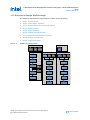
1.5. Reference Design Walkthrough
The following steps describe implementation of SUPR with a flat design:
•Step 1: Getting Started
•Step 2: Create Design Partitions
•Step 3: Allocate Placement and Routing Regions
•Step 4: Define Personas
•Step 5: Create Revisions
•Step 6: Compile the Base Revision
•Step 7: Setup PR Implementation Revisions
•Step 8: Change the SUPR Logic
•Step 9: Program the Board
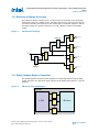
Figure 3. SUPR Compilation Flow
IP Generation
Synthesis
Fitter
Assembler
SOF and RBF
Static
QDB
Base Compilation
IP Generation
Synthesis
PR Compilation
Fitter
Assembler
SOF and RBF
IP Generation
Synthesis
SUPR Compilation
Fitter
Assembler
SOF
Final Static Exports
PR
QDB
Static
QDB
SUPR
-Initial QDB
Snapshot SUPR Exports
SUPR -New
QDB
SUPR -
Initial QDB
New PR
Persona
Static
QDB
SUPR
QDB
New SUPR
Logic
Static
QDB
SUPR
QDB
1. Static Update Partial Reconfiguration Tutorial for Intel® Agilex™ F-Series FPGA Development
Board
749443 | 2022.10.24
AN 987: Static Update Partial Reconfiguration Tutorial: for Intel Agilex F-
Series FPGA Development Board Send Feedback
6

1.5.1. Step 1: Getting Started
To copy the reference design files to your working environment and compile the
blinking_led flat design:
1. Before you begin, Download Reference Design Files on page 5.
2. Create the agilex_pcie_devkit_blinking_led_supr directory in your
working environment.
3. Copy the downloaded tutorials/agilex_pcie_devkit_blinking_led/flat
sub-folder to the agilex_pcie_devkit_blinking_led_supr directory.
4. In the Intel Quartus Prime Pro Edition software, click File ➤ Open Project and
open /flat/blinking_led.qpf.
5. To compile the base design, click Processing ➤ Start Compilation. The Timing
Analyzer reports open automatically when compilation is complete. You can close
the Timing Analyzer for now.
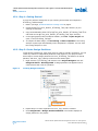
1.5.2. Step 2: Create Design Partitions
Create design partitions for each region that you want to partially reconfigure. You can
create any number of independent partitions or PR regions in your project. Follow
these steps to create design partitions for the u_blinking_led instance as the PR
partition, and the u_top_counter instance as the SUPR region:
1. Right-click the u_blinking_led instance in the Project Navigator and click
Design Partition ➤ Reconfigurable. A design partition icon appears next to
each instance that is set as a partition.
Figure 4. Creating Design Partitions
2. Repeat step 1 to create a partition for the u_top_counter instance.
3. Click Assignments ➤ Design Partitions Window. The window displays all
design partitions in the project.
1. Static Update Partial Reconfiguration Tutorial for Intel® Agilex™ F-Series FPGA Development
Board
749443 | 2022.10.24
Send Feedback AN 987: Static Update Partial Reconfiguration Tutorial: for Intel Agilex F-
Series FPGA Development Board
7

Figure 5. Design Partitions Window
Click to Add Columns
4. Double-click the blinking_led Partition Name cell to rename it to
pr_partition. Similarly, rename the top_counter partition to
supr_partition.
Alternatively, adding the following lines to blinking_led.qsf creates these
partitions:
set_instance_assignment -name PARTITION pr_partition \
-to u_blinking_led -entity top
set_instance_assignment -name PARTIAL_RECONFIGURATION_PARTITION ON \
-to u_blinking_led -entity top
set_instance_assignment -name PARTITION supr_partition \
-to u_top_counter -entity top
set_instance_assignment -name PARTIAL_RECONFIGURATION_PARTITION ON \
-to u_top_counter -entity top
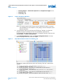
1.5.3. Step 3: Allocate Placement and Routing Regions
For every base revision that you create, the Compiler uses the PR partition region
allocation to place the corresponding persona core in the reserved region. Follow these
steps to locate and assign a PR region in the device floorplan for your base revision:
1. In the Project Navigator Hierarchy tab, right-click the u_blinking_led
instance, and then click Logic Lock Region ➤ Create New Logic Lock Region.
The region appears in the Logic Lock Regions window.
2. Specify a region Width of 5 and Height of 5.
3. Specify the placement region coordinates for u_blinking_led in the Origin
column. The origin corresponds to the lower-left corner of the region. Specify the
Origin as X166_Y199. The Compiler calculates (X170 Y203) as the top-right
coordinate.
4. Enable the Reserved and Core-Only options for the region.
5. Double-click the Routing Region option. The Logic Lock Routing Region
Settings dialog box appears.
6. For the Routing Type, select Fixed with expansion. This option automatically
assigns an Expansion length of one.
7. Repeat the previous steps to allocate the following resources for the
u_top_counter partition:
•Height—5
•Width—5
•Origin—X173_Y199
1. Static Update Partial Reconfiguration Tutorial for Intel® Agilex™ F-Series FPGA Development
Board
749443 | 2022.10.24
AN 987: Static Update Partial Reconfiguration Tutorial: for Intel Agilex F-
Series FPGA Development Board Send Feedback
8

•Routing Region— Fixed with expansion with Expansion length of one.
•Reserved—On
•Core-Only—On
Figure 6. Logic Lock Regions Window
Note: The routing region must be larger than the placement region, to provide
extra flexibility for the Compiler's routing stage, when the Compiler routes
different personas.
8. Your placement region must enclose the blinking_led logic. To select the
placement region by locating the node in Chip Planner, right-click the
u_blinking_led region name in the Logic Lock Regions window, and then click
Locate Node ➤ Locate in Chip Planner.
9. Under Partition Reports, double-click Report Design Partitions. The Chip
Planner highlights and color codes the region.
Figure 7. Chip Planner Node Location for blinking_led
Alternatively, adding the following lines to blinking_led.qsf creates these
regions:
set_instance_assignment -name PARTITION pr_partition -to \
u_blinking_led -entity top
set_instance_assignment -name PARTIAL_RECONFIGURATION_PARTITION ON \
-to u_blinking_led -entity top
set_instance_assignment -name PARTITION supr_partition -to u_top_counter \
-entity top
set_instance_assignment -name PARTIAL_RECONFIGURATION_PARTITION ON -to \
u_top_counter -entity top
set_instance_assignment -name PLACE_REGION "X166 Y199 X170 Y203" -to \
1. Static Update Partial Reconfiguration Tutorial for Intel® Agilex™ F-Series FPGA Development
Board
749443 | 2022.10.24
Send Feedback AN 987: Static Update Partial Reconfiguration Tutorial: for Intel Agilex F-
Series FPGA Development Board
9

u_blinking_led
set_instance_assignment -name RESERVE_PLACE_REGION ON -to u_blinking_led
set_instance_assignment -name CORE_ONLY_PLACE_REGION ON -to u_blinking_led
set_instance_assignment -name REGION_NAME pr_partition -to u_blinking_led
set_instance_assignment -name ROUTE_REGION "X165 Y198 X171 Y204" -to \
u_blinking_led
set_instance_assignment -name RESERVE_ROUTE_REGION OFF -to u_blinking_led
set_instance_assignment -name PLACE_REGION "X173 Y199 X177 Y203" -to \
u_top_counter
set_instance_assignment -name RESERVE_PLACE_REGION ON -to u_top_counter
set_instance_assignment -name CORE_ONLY_PLACE_REGION ON -to u_top_counter
set_instance_assignment -name REGION_NAME supr_partition -to u_top_counter
set_instance_assignment -name ROUTE_REGION "X172 Y198 X178 Y204" -to \
u_top_counter
set_instance_assignment -name RESERVE_ROUTE_REGION OFF -to u_top_counter
1.5.4. Step 4: Define Personas
This reference design defines three separate personas for the single PR partition, and
one SUPR persona for the SUPR region. Follow these steps to define and include these
personas in your project. If using the Intel Quartus Prime Text Editor, disable Add file
to current project when saving the files.
1. Create new blinking_led_slow.sv, blinking_led_empty.sv, and
top_counter_fast.sv SystemVerilog files in your working directory. Confirm
that blinking_led.sv is already present in the working directory.
2. Enter the following contents for the SystemVerilog files:
Table 2. Reference Design Personas SystemVerilog
File Name Description Code
blinking_led_slow.sv LEDs blink slower `timescale 1 ps / 1 ps
`default_nettype none
module blinking_led_slow (
// clock
input wire clock,
input wire reset,
input wire [31:0] counter,
// Control signals for the LEDs
output wire led_two_on,
output wire led_three_on
);
localparam COUNTER_TAP = 27;
reg led_two_on_r;
reg led_three_on_r;
assign led_two_on = led_two_on_r;
assign led_three_on = led_three_on_r;
always_ff @(posedge clock) begin
led_two_on_r <= counter[COUNTER_TAP];
led_three_on_r <= counter[COUNTER_TAP];
end
endmodule
blinking_led_empty.sv LEDs stay ON `timescale 1 ps / 1 ps
`default_nettype none
module blinking_led_empty(
// clock
input wire clock,
input wire reset,
input wire [31:0] counter,
// Control signals for the LEDs
output wire led_two_on,
output wire led_three_on
);
continued...
1. Static Update Partial Reconfiguration Tutorial for Intel® Agilex™ F-Series FPGA Development
Board
749443 | 2022.10.24
AN 987: Static Update Partial Reconfiguration Tutorial: for Intel Agilex F-
Series FPGA Development Board Send Feedback
10

File Name Description Code
// LED is active low
assign led_two_on = 1'b0;
assign led_three_on = 1'b0;
endmodule
top_counter_fast.sv Second SUPR
persona `timescale 1 ps / 1 ps
`default_nettype none
module top_counter_fast (
// Control signals for the LEDs
output wire led_one_on,
output wire [31:0] count,
// clock
input wire clock
);
localparam COUNTER_TAP = 23;
reg [31:0] count_d;
assign count = count_d;
assign led_one_on = count_d[COUNTER_TAP];
always_ff @(posedge clock) begin
count_d <= count_d + 2;
end
endmodule
3. Click File ➤ Save As and save the .sv files in the current project directory.
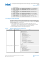
1.5.5. Step 5: Create Revisions
The PR design flow uses the project revisions feature in the Intel Quartus Prime
software. Your initial design is the base revision, where you define the static region
boundaries and reconfigurable regions on the FPGA.
From the base revision, you create additional revisions. These revisions contain the
different implementations for the PR regions. However, all PR implementation revisions
use the same top-level placement and routing results from the base revision.
To compile a PR design, you create a PR implementation revision for each persona. In
addition, you must assign either the Partial Reconfiguration - Base or Partial
Reconfiguration - Persona Implementation revision type for each of the revisions.
The following table lists the revision name and the revision type for each of the
revisions. The impl_blinking_led_supr_new.qsf revision is the SUPR persona
implementation.
Table 3. Revision Names and Types
Revision Name Revision Type
blinking_led Partial Reconfiguration - Base
blinking_led_default Partial Reconfiguration - Persona Implementation
blinking_led_slow Partial Reconfiguration - Persona Implementation
blinking_led_empty Partial Reconfiguration - Persona Implementation
impl_blinking_led_supr_new Partial Reconfiguration - Persona Implementation
1.5.5.1. Setting the Base Revision
Follow these steps to set blinking_led as the base revision:
1. Static Update Partial Reconfiguration Tutorial for Intel® Agilex™ F-Series FPGA Development
Board
749443 | 2022.10.24
Send Feedback AN 987: Static Update Partial Reconfiguration Tutorial: for Intel Agilex F-
Series FPGA Development Board
11

1. Click Project ➤ Revisions.
2. For Revision Type, select Partial Reconfiguration - Base.
This step adds the following to the blinking_led.qsf:
##blinking_led.qsf
set_global_assignment -name REVISION_TYPE PR_BASE
1.5.5.2. Creating Implementation Revisions
Follow these steps to create the implementation revisions:
1. In the Revisions dialog box, double-click <<new revision>>.
2. In Revision name, specify blinking_led_default and select blinking_led
for Based on revision.
3. For the Revision type, select Partial Reconfiguration - Persona
Implementation.
4. Disable the Set as current revision option.
5. Repeat steps 2 through 5 to set the Revision type for the other implementation
revisions:
Revision Name Revision Type Based on Revision
blinking_led_slow Partial Reconfiguration - Persona
Implementation
blinking_led
blinking_led_empty Partial Reconfiguration - Persona
Implementation
blinking_led
impl_blinking_led_supr_new Partial Reconfiguration - Persona
Implementation
blinking_led
1. Static Update Partial Reconfiguration Tutorial for Intel® Agilex™ F-Series FPGA Development
Board
749443 | 2022.10.24
AN 987: Static Update Partial Reconfiguration Tutorial: for Intel Agilex F-
Series FPGA Development Board Send Feedback
12

Figure 8. Creating Implementation Revisions
Each .qsf file now contains the following assignment:
set_global_assignment -name REVISION_TYPE PR_IMPL
set_instance_assignment -name ENTITY_REBINDING place_holder -to u_top_counter
set_instance_assignment -name ENTITY_REBINDING place_holder -to
u_blinking_led
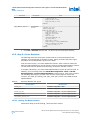
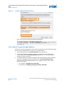
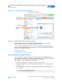
1.5.6. Step 6: Compile the Base Revision
Follow these steps to compile the base revision and export the static and SUPR regions
for later use in implementation revisions for new PR personas:
1. Set blinking_led as the Current Revision if not already set.
2. In the Design Partitions Window, click the (…) adjacent to the farthest right
column and enable the Post Final Export File column. You can also disable or
change the order of columns.
3. To automatically export the final snapshot of PR implementation design partitions
after each compilation, specify the following for the Post Final Export File
options for the root and SUPR partitions. The .qdb files export to the project
directory by default.
• root_partition—blinking_led_static.qdb
• supr_partition—blinking_led_supr_partition_final.qdb
1. Static Update Partial Reconfiguration Tutorial for Intel® Agilex™ F-Series FPGA Development
Board
749443 | 2022.10.24
Send Feedback AN 987: Static Update Partial Reconfiguration Tutorial: for Intel Agilex F-
Series FPGA Development Board
13

Figure 9. Auto Export in Design Partitions Window
Alternatively, the following .qsf assignments export the partitions automatically
after each compilation:
set_instance_assignment -name EXPORT_PARTITION_SNAPSHOT_FINAL \
blinking_led_static.qdb -to | -entity top
set_instance_assignment -name EXPORT_PARTITION_SNAPSHOT_FINAL \
blinking_led_supr_partition_final.qdb -to u_top_counter \
-entity top
4. To compile the blinking_led base revision, click Processing ➤ Start
Compilation. Alternatively, you can use the following command to compile this
revision:
quartus_sh --flow compile blinking_led -c blinking_led
After successful compilation, the following files appear in the project directory:
•blinking_led.sof
•blinking_led.pr_partition.rbf
•blinking_led.supr_partition.rbf
•blinking_led_static.qdb
•blinking_led_supr_partition_final.qdb
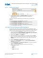
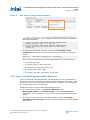
1.5.7. Step 7: Set Up PR Implementation Revisions
You must prepare the PR implementation revisions before you can generate the PR
bitstream for device programming. This setup includes adding the static region .qdb
file as the source file for each implementation revision. In addition, you must specify
the corresponding entity of the PR region.
Follow these steps to setup the PR implementation revisions:
1. To set the current revision, click Project ➤ Revisions, select
blinking_led_default as the Revision name, and then click Set Current.
Alternatively, you can select the current revision on the main Intel Quartus Prime
toolbar.
2. To verify the correct source for this implementation revision, click Project ➤
Add/Remove Files in Project. Confirm that the blinking_led.sv file appears
in the file list.
1. Static Update Partial Reconfiguration Tutorial for Intel® Agilex™ F-Series FPGA Development
Board
749443 | 2022.10.24
AN 987: Static Update Partial Reconfiguration Tutorial: for Intel Agilex F-
Series FPGA Development Board Send Feedback
14

3. To verify the correct source file for the implementation revisions, click Project ➤
Add/Remove files in Project, and add the following source files for the
implementation revisions. If present, remove blinking_led.sv from the list of
project files.
Implementation Revision Name Source File
blinking_led_empty blinking_led_empty.sv
blinking_led_slow blinking_led_slow.sv
4. Set blinking_led_default as the Current Revision.
5. To specify the .qdb file as the source for root_partition, click Assignments
➤ Design Partitions Window. Double-click the Partition Database File cell
and specify the blinking_led_static.qdb file.
6. Similarly, specify blinking_led_supr_partition_final.qdb as the
Partition Database File for supr_partition.
Figure 10.
Alternatively, use the following .qsf assignments to specify the .qdb:
set_instance_assignment -name QDB_FILE_PARTITION \
blinking_led_static.qdb -to |
set_instance_assignment -name QDB_FILE_PARTITION \
blinking_led_supr_partition_final.qdb -to u_top_counter
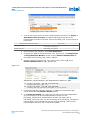
7. In the Design Partitions Window, click the (…) adjacent to the farthest right
column and enable the Entity Re-binding column.
8. In the Entity Re-binding cell, specify the new entity name for the PR partition
you are changing in the current implementation revision. For the
blinking_led_default implementation revision, the entity name is
blinking_led. In this case, you are overwriting the u_blinking_led instance
from the base revision compile with the new entity blinking_led. For other
implementation revisions, refer to the following table:
1. Static Update Partial Reconfiguration Tutorial for Intel® Agilex™ F-Series FPGA Development
Board
749443 | 2022.10.24
Send Feedback AN 987: Static Update Partial Reconfiguration Tutorial: for Intel Agilex F-
Series FPGA Development Board
15

Revision Entity Re-binding Value
blinking_led_slow blinking_led_slow
blinking_led_empty blinking_led_empty
Figure 11. Entity Rebinding
Alternatively, you can use the following lines in each revision's .qsf to set the
assignments:
##blinking_led_default.qsf
set_instance_assignment -name ENTITY_REBINDING blinking_led \
-to u_blinking_led
##blinking_led_slow.qsf
set_instance_assignment -name ENTITY_REBINDING blinking_led_slow \
-to u_blinking_led
##blinking_led_empty.qsf
set_instance_assignment -name ENTITY_REBINDING blinking_led_empty \
-to u_blinking_led
9. Delete the place_holder text from the Entity Re-binding cell for
supr_partition.
10. To compile the design, click Processing ➤ Start Compilation. Alternatively, use
the following command to compile this project:
quartus_sh --flow compile blinking_led –c blinking_led_default
11. Repeat steps 4 through 11 to prepare and compile the blinking_led_slow and
blinking_led_empty implementation revisions.
1.5.8. Step 8: Change the SUPR Logic
To change the functionality of the logic within the SUPR partition, you must change the
SUPR partition source. Complete the following steps to replace the u_top_counter
instance in the SUPR partition with the top_counter_fast entity.
1. To set the SUPR implementation revision as current, click Project ➤ Revisions
and set impl_blinking_led_supr_new as the current revision, or select the
revision on the Intel Quartus Prime main toolbar.
2. To verify the correct source file for the implementation revision, click Project ➤
Add/Remove files in Project, and verify that top_counter_fast.sv is the
source for the impl_blinking_led_supr_new implementation revision. If
present, remove top_counter.sv from the list of project files.
1. Static Update Partial Reconfiguration Tutorial for Intel® Agilex™ F-Series FPGA Development
Board
749443 | 2022.10.24
AN 987: Static Update Partial Reconfiguration Tutorial: for Intel Agilex F-
Series FPGA Development Board Send Feedback
16

3. To specify the .qdb file associated with the root partition, click Assignments ➤
Design Partitions Window, and then double-click the Partition Database File
cell to specify blinking_led_static.qdb.
Alternatively, use the following command to assign this file:
set_instance_assignment -name QDB_FILE_PARTITION \
blinking_led_static.qdb -to |
4. In the Entity Re-binding cell for pr_partition, specify the appropriate entity
name. For this example, specify the blinking_led_empty entity. In this case,
you are overwriting the u_blinking_led instance from the base revision compile
with the new entity blinking_led_empty. The following line now exists in
the .qsf:
##impl_blinking_led_supr_new.qsf
set_instance_assignment -name ENTITY_REBINDING blinking_led_empty \
-to u_blinking_led
5. In the Entity Re-binding cell for supr_partition, specify the
top_counter_fast entity. top_counter_fast is the name of the static entity
that replaces u_top_counter when you complete the SUPR.
##impl_blinking_led_supr_new.qsf
set_instance_assignment -name ENTITY_REBINDING top_counter_fast \
-to u_top_counter
6. To compile the design, click Processing ➤ Start Compilation. Alternatively, use
following command to compile this project revision:
quartus_sh --flow compile blinking_led –c \
impl_blinking_led_supr_new
1. Static Update Partial Reconfiguration Tutorial for Intel® Agilex™ F-Series FPGA Development
Board
749443 | 2022.10.24
Send Feedback AN 987: Static Update Partial Reconfiguration Tutorial: for Intel Agilex F-
Series FPGA Development Board
17

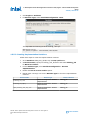
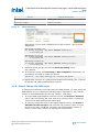
1.5.9. Step 9: Program the Board
Follow these steps to connect and program the Intel Agilex F-Series FPGA
development board.
1. Connect the power supply to the Intel Agilex F-Series FPGA development board.
2. Connect a USB cable between your PC USB port and the USB programming
hardware on the development board.
3. Open the Intel Quartus Prime software, and then click Tools ➤ Programmer.
Refer to Programming a Development Board.
4. In the Programmer, click Hardware Setup, and then select USB-Blaster.
5. Click Auto Detect, and then select the AGFB014R24B device.
6. Click OK. The Intel Quartus Prime software detects and updates the Programmer
with the three FPGA devices on the board.
7. Select the AGFB014R24B device, click Change File, and load the
blinking_led_default.sof file.
8. Enable Program/Configure for the blinking_led_default.sof file.
9. Click Start and wait for the progress bar to reach 100%.
10. Observe the LEDs on the board blinking.
11. To program only the PR region, right-click the blinking_led_default.sof file
in the Programmer and click Add PR Programming File.
12. Select the blinking_led_slow.pr_partition.rbf file.
13. Disable Program/Configure for the blinking_led_default.sof file.
14. Enable Program/Configure for the blinking_led_slow.pr_partition.rbf
file, and then click Start. On the board, observe LED[0] and LED[1] continuing
to blink. When the progress bar reaches 100%, LED[2] and LED[3] blink slower.
15. To re-program the PR region, right-click the .rbf file in the Programmer, and then
click Change PR Programing File.
16. Select the .rbf files for the other two personas to observe the behavior on the
board. Loading the blinking_led_default.pr_partition.rbf file causes
the LEDs to blink at the original frequency, and loading the
blinking_led_empty.pr_partition.rbf file causes the LEDs to stay ON.
17. To change the SUPR logic, repeat step 7 above to select the
impl_blinking_led_supr_new.sof. After changing this file, led [0:1] now
blinks at a faster rate than before. The other PR .rbf files are also compatible
with the new .sof.
Note: The Assembler generates an .rbf file for the SUPR region. However, you
should not use this file to reprogram the FPGA at runtime because the SUPR
partition does not instantiate the freeze bridge, PR region controller, and
other logic in the overall system. When you make changes to the SUPR
partition logic, you must reprogram the full .sof file from the SUPR
implementation revision compilation.
1. Static Update Partial Reconfiguration Tutorial for Intel® Agilex™ F-Series FPGA Development
Board
749443 | 2022.10.24
AN 987: Static Update Partial Reconfiguration Tutorial: for Intel Agilex F-
Series FPGA Development Board Send Feedback
18

Figure 12. Programming a Development Board
Starts Download of
Configuration Data
Adds SOF File
Adds RBF to Program
PR region
Enables Program or Configuration
1.5.9.1. Troubleshooting PR Programming Errors
Ensuring proper setup of the Intel Quartus Prime Programmer and connected
hardware helps to avoid any errors during PR programming.
If you face any PR programming errors, refer to "Troubleshooting PR Programming
Errors" in the Intel Quartus Prime Pro Edition User Guide: Partial Reconfiguration for
step-by-step troubleshooting tips.
Related Information
Troubleshooting PR Programming Errors
1.5.10. Modifying the SUPR Partition
You can modify an existing SUPR partition. After modifying the SUPR partition, you
must compile it, generate the .sof file, and program the board, without compiling the
other personas. For example, follow these steps to change the
top_counter_fast.sv module to count faster:
1. Set impl_blinking_led_supr_new as the current revision.
2. In the top_counter_fast.sv file, replace the count_d + 2 statement with
count_d + 4.
3. Run the following commands to re-synthesize the SUPR block and generate the
new .sof file:
quartus_sh --flow compile blinking_led \
-c impl_blinking_led_supr_new
1. Static Update Partial Reconfiguration Tutorial for Intel® Agilex™ F-Series FPGA Development
Board
749443 | 2022.10.24
Send Feedback AN 987: Static Update Partial Reconfiguration Tutorial: for Intel Agilex F-
Series FPGA Development Board
19

The resulting .sof now contains the new SUPR region, and uses blinking_led
for the default (power-on) persona.
1.6. Document Revision History of AN 987: Static Update Partial
Reconfiguration Tutorial Revision History
Document Version Intel Quartus Prime
Version
Changes
2022.10.24 22.3 Initial release of the document.
1. Static Update Partial Reconfiguration Tutorial for Intel® Agilex™ F-Series FPGA Development
Board
749443 | 2022.10.24
AN 987: Static Update Partial Reconfiguration Tutorial: for Intel Agilex F-
Series FPGA Development Board Send Feedback
20
-
 1
1
-
 2
2
-
 3
3
-
 4
4
-
 5
5
-
 6
6
-
 7
7
-
 8
8
-
 9
9
-
 10
10
-
 11
11
-
 12
12
-
 13
13
-
 14
14
-
 15
15
-
 16
16
-
 17
17
-
 18
18
-
 19
19
-
 20
20


Ask a question and I''ll find the answer in the document
Finding information in a document is now easier with AI
Related papers
-
Intel 750856 User guide
-
Intel 23.2 User guide
-
Intel AN 903 User guide
-
-
Intel Mailbox Client Intel FPGA IP User guide
-
Intel Quartus Prime Design Software User guide
-
Intel Low Latency User guide
-
Intel Interlaken User guide
-
Intel F Tile Serial Lite IV User guide
-
Intel Triple-Speed User guide
Other documents
-
 Terasic DE10-Agilex User manual
-
 Terasic DE10-Agilex User manual
-
 Terasic DE10-Agilex User manual
-
Altera UG-01080 User manual
-
-
 Terasic Agilex-SOM User manual
-
 Terasic A7SK User manual
-
 Terasic A7SK User manual
-
-
Altera Stratix III Design Manuallines


