Page is loading ...


Contents
Introduction to the Protocol-Specific and Native Transceiver PHYs............... 1-1
Protocol-Specific Transceiver PHYs.........................................................................................................1-1
Native Transceiver PHYs ...........................................................................................................................1-2
Non-Protocol-Specific Transceiver PHYs................................................................................................1-4
Transceiver PHY Modules..........................................................................................................................1-4
Transceiver Reconfiguration Controller...................................................................................................1-5
Resetting the Transceiver PHY..................................................................................................................1-5
Running a Simulation Testbench.............................................................................................................. 1-6
Unsupported Features.................................................................................................................................1-9
Getting Started Overview....................................................................................2-1
Installation and Licensing of IP Cores......................................................................................................2-1
Design Flows.................................................................................................................................................2-2
MegaWizard Plug-In Manager Flow.........................................................................................................2-3
Specifying Parameters..................................................................................................................... 2-3
Simulate the IP Core........................................................................................................................2-4
10GBASE-R PHY IP Core...................................................................................3-1
10GBASE-R PHY Release Information.................................................................................................... 3-6
10GBASE-R PHY Device Family Support................................................................................................3-6
10GBASE-R PHY Performance and Resource Utilization for Stratix IV Devices..............................3-7
10GBASE-R PHY Performance and Resource Utilization for Arria V GT Devices.......................... 3-7
10GBASE-R PHY Performance and Resource Utilization for Arria V GZ and Stratix V
Devices.....................................................................................................................................................3-8
Parameterizing the 10GBASE-R PHY.......................................................................................................3-8
General Option Parameters........................................................................................................................3-9
Analog Parameters for Stratix IV Devices..............................................................................................3-12
10GBASE-R PHY Interfaces.....................................................................................................................3-13
10GBASE-R PHY Data Interfaces...........................................................................................................3-14
10GBASE-R PHY Status, 1588, and PLL Reference Clock Interfaces................................................3-17
Optional Reset Control and Status Interface......................................................................................... 3-18
10GBASE-R PHY Clocks for Arria V GT Devices................................................................................3-19
10GBASE-R PHY Clocks for Arria V GZ Devices................................................................................3-20
10GBASE-R PHY Clocks for Stratix IV Devices...................................................................................3-21
10GBASE-R PHY Clocks for Stratix V Devices.....................................................................................3-22
10GBASE-R PHY Register Interface and Register Descriptions.........................................................3-23
10GBASE-R PHY Dynamic Reconfiguration for Stratix IV Devices.................................................3-28
10GBASE-R PHY Dynamic Reconfiguration for Arria V and Stratix V Devices.............................3-29
1588 Delay Requirements.........................................................................................................................3-30
10GBASE-R PHY TimeQuest Timing Constraints.............................................................................. 3-30
10GBASE-R PHY Simulation Files and Example Testbench..............................................................3-32
TOC-2
Altera Transceiver PHY IP Core User Guide
Altera Corporation

Backplane Ethernet 10GBASE-KR PHY IP Core with Early Access FEC
Option..............................................................................................................4-1
10GBASE-KR PHY Release Information................................................................................................. 4-3
Device Family Support................................................................................................................................4-3
10GBASE-KR PHY Performance and Resource Utilization..................................................................4-3
Parameterizing the 10GBASE-KR PHY....................................................................................................4-4
10GBASE-KR Link Training Parameters .................................................................................... 4-5
10GBASE-KR Auto-Negotiation and Link Training Parameters.............................................4-7
10GBASE-R Parameters..................................................................................................................4-7
1GbE Parameters..............................................................................................................................4-9
Speed Detection Parameters.........................................................................................................4-10
PHY Analog Parameters...............................................................................................................4-10
10GBASE-KR PHY IP Core Functional Description........................................................................... 4-10
10GBASE-KR PHY Arbitration Logic Requirements...........................................................................4-14
10GBASE-KR PHY State Machine Logic Requirements......................................................................4-15
Forward Error Correction (Clause 74)................................................................................................... 4-15
10BASE-KR PHY Interfaces.....................................................................................................................4-19
10GBASE-KR PHY Clock and Reset Interfaces.................................................................................... 4-20
10GBASE-KR PHY Data Interfaces............................................................................................ 4-22
10GBASE-KR PHY Control and Status Interfaces....................................................................4-25
Daisy-Chain Interface Signals......................................................................................................4-27
Embedded Processor Interface Signals.......................................................................................4-28
Dynamic Reconfiguration Interface Signals.............................................................................. 4-29
Register Interface Signals..........................................................................................................................4-32
10GBASE-KR PHY Register Definitions................................................................................................4-32
PMA Registers............................................................................................................................................4-47
PCS Registers..............................................................................................................................................4-48
Creating a 10GBASE-KR Design.............................................................................................................4-49
Editing a 10GBASE-KR MIF File ........................................................................................................... 4-50
Design Example..........................................................................................................................................4-52
SDC Timing Constraints.......................................................................................................................... 4-53
Acronyms....................................................................................................................................................4-53
1G/10 Gbps Ethernet PHY IP Core.....................................................................5-1
1G/10GbE PHY Release Information....................................................................................................... 5-2
Device Family Support................................................................................................................................5-3
1G/10 GbE PHY Performance and Resource Utilization.......................................................................5-3
Parameterizing the 1G/10GbE PHY..........................................................................................................5-4
1GbE Parameters..........................................................................................................................................5-4
Speed Detection Parameters.......................................................................................................................5-5
PHY Analog Parameters.............................................................................................................................5-6
1G/10GbE PHY Interfaces..........................................................................................................................5-7
1G/10GbE PHY Clock and Reset Interfaces............................................................................................ 5-8
1G/10GbE PHY Data Interfaces................................................................................................................ 5-9
XGMII Mapping to Standard SDR XGMII Data.................................................................................. 5-11
Serial Data Interface.................................................................................................................................. 5-12
Altera Transceiver PHY IP Core User Guide
TOC-3
Altera Corporation

1G/10GbE Control and Status Interfaces...............................................................................................5-12
Register Interface Signals..........................................................................................................................5-14
1G/10GbE PHY Register Definitions .....................................................................................................5-15
PMA Registers............................................................................................................................................5-16
PCS Registers..............................................................................................................................................5-17
1G/10 GbE GMII PCS Registers..............................................................................................................5-18
PMA Registers............................................................................................................................................5-20
1G/10GbE Dynamic Reconfiguration from 1G to 10GbE...................................................................5-21
1G/10GbE PHY Arbitration Logic Requirements.................................................................................5-22
1G/10GbE PHY State Machine Logic Requirements............................................................................5-23
Editing a 1G/10GbE MIF File ................................................................................................................. 5-23
Creating a 1G/10GbE Design...................................................................................................................5-24
Dynamic Reconfiguration Interface Signals.......................................................................................... 5-25
1G/10 Gbps Ethernet PHY IP Core.........................................................................................................5-27
Design Example..........................................................................................................................................5-29
Simulation Support....................................................................................................................................5-30
TimeQuest Timing Constraints...............................................................................................................5-30
Acronyms....................................................................................................................................................5-30
XAUI PHY IP Core............................................................................................. 6-1
XAUI PHY Release Information............................................................................................................... 6-2
XAUI PHY Device Family Support...........................................................................................................6-2
XAUI PHY Performance and Resource Utilization for Stratix IV Devices.........................................6-3
XAUI PHY Performance and Resource Utilization for Arria V GZ and Stratix V Devices............. 6-3
Parameterizing the XAUI PHY..................................................................................................................6-3
XAUI PHY General Parameters................................................................................................................ 6-4
XAUI PHY Analog Parameters..................................................................................................................6-6
XAUI PHY Analog Parameters for Arria II GX, Cyclone IV GX, HardCopy IV and Stratix IV
Devices.....................................................................................................................................................6-6
Advanced Options Parameters.................................................................................................................. 6-8
XAUI PHY Configurations........................................................................................................................ 6-9
XAUI PHY Ports........................................................................................................................................6-10
XAUI PHY Data Interfaces...................................................................................................................... 6-11
SDR XGMII TX Interface.............................................................................................................6-12
SDR XGMII RX Interface.............................................................................................................6-13
Transceiver Serial Data Interface.................................................................................................6-13
XAUI PHY Clocks, Reset, and Powerdown Interfaces.........................................................................6-13
XAUI PHY PMA Channel Controller Interface....................................................................................6-15
XAUI PHY Optional PMA Control and Status Interface....................................................................6-16
XAUI PHY Register Interface and Register Descriptions....................................................................6-18
XAUI PHY Dynamic Reconfiguration for Arria II GX, Cyclone IV GX, HardCopy IV GX, and
Stratix IV GX.........................................................................................................................................6-25
XAUI PHY Dynamic Reconfiguration for Arria V, Arria V GZ, Cyclone V and Stratix V
Devices...................................................................................................................................................6-25
Logical Lane Assignment Restriction..........................................................................................6-26
XAUI PHY Dynamic Reconfiguration Interface Signals......................................................... 6-26
SDC Timing Constraints.......................................................................................................................... 6-27
Simulation Files and Example Testbench...............................................................................................6-27
TOC-4
Altera Transceiver PHY IP Core User Guide
Altera Corporation

Interlaken PHY IP Core......................................................................................7-1
Interlaken PHY Device Family Support...................................................................................................7-2
Parameterizing the Interlaken PHY..........................................................................................................7-3
Interlaken PHY General Parameters.........................................................................................................7-3
Interlaken PHY Optional Port Parameters.............................................................................................. 7-5
Interlaken PHY Analog Parameters..........................................................................................................7-5
Interlaken PHY Interfaces.......................................................................................................................... 7-6
Interlaken PHY Avalon-ST TX Interface................................................................................................. 7-7
Interlaken PHY Avalon-ST RX Interface...............................................................................................7-10
Interlaken PHY TX and RX Serial Interface..........................................................................................7-14
Interlaken PHY PLL Interface..................................................................................................................7-14
Interlaken Optional Clocks for Deskew..................................................................................................7-15
Interlaken PHY Register Interface and Register Descriptions............................................................ 7-16
Why Transceiver Dynamic Reconfiguration.........................................................................................7-20
Dynamic Transceiver Reconfiguration Interface..................................................................................7-20
Interlaken PHY TimeQuest Timing Constraints..................................................................................7-21
Interlaken PHY Simulation Files and Example Testbench..................................................................7-21
PHY IP Core for PCI Express (PIPE) .................................................................8-1
PHY for PCIe (PIPE) Device Family Support..........................................................................................8-3
PHY for PCIe (PIPE) Resource Utilization..............................................................................................8-3
Parameterizing the PHY IP Core for PCI Express (PIPE).....................................................................8-3
PHY for PCIe (PIPE) General Options Parameters................................................................................8-3
PHY for PCIe (PIPE) Interfaces.................................................................................................................8-6
PHY for PCIe (PIPE) Input Data from the PHY MAC..........................................................................8-7
PHY for PCIe (PIPE) Output Data to the PHY MAC..........................................................................8-11
PHY for PCIe (PIPE) Clocks....................................................................................................................8-13
PHY for PCIe (PIPE) Clock SDC Timing Constraints for Gen3 Designs.........................................8-13
PHY for PCIe (PIPE) Optional Status Interface....................................................................................8-14
PHY for PCIe (PIPE) Serial Data Interface............................................................................................8-14
PHY for PCIe (PIPE) Register Interface and Register Descriptions...................................................8-15
PHY for PCIe (PIPE) Link Equalization for Gen3 Data Rate..............................................................8-21
Phase 0.............................................................................................................................................8-22
Phase 1.............................................................................................................................................8-22
Phase 2 (Optional).........................................................................................................................8-22
Phase 3 (Optional).........................................................................................................................8-23
Recommendations for Tuning Link Partner’s Transmitter.....................................................8-23
Enabling Dynamic PMA Tuning for PCIe Gen3.................................................................................. 8-23
PHY for PCIe (PIPE) Dynamic Reconfiguration..................................................................................8-24
Logical Lane Assignment Restriction..........................................................................................8-25
PHY for PCIe (PIPE) Simulation Files and Example Testbench........................................................8-25
Custom PHY IP Core.......................................................................................... 9-1
Device Family Support................................................................................................................................9-2
Performance and Resource Utilization.....................................................................................................9-2
Altera Transceiver PHY IP Core User Guide
TOC-5
Altera Corporation

Parameterizing the Custom PHY.............................................................................................................. 9-3
General Options Parameters.......................................................................................................... 9-3
Word Alignment Parameters.........................................................................................................9-7
Rate Match FIFO Parameters.........................................................................................................9-9
8B/10B Encoder and Decoder Parameters.................................................................................9-10
Byte Order Parameters..................................................................................................................9-11
PLL Reconfiguration Parameters.................................................................................................9-14
Analog Parameters.........................................................................................................................9-16
Presets for Ethernet........................................................................................................................9-16
Interfaces.....................................................................................................................................................9-19
Data Interfaces................................................................................................................................9-19
Clock Interface............................................................................................................................... 9-23
Optional Status Interface.............................................................................................................. 9-24
Optional Reset Control and Status Interface............................................................................. 9-26
Register Interface and Register Descriptions.............................................................................9-27
Custom PHY IP Core Registers...................................................................................................9-29
SDC Timing Constraints.............................................................................................................. 9-33
Dynamic Reconfiguration............................................................................................................ 9-33
Low Latency PHY IP Core.................................................................................10-1
Device Family Support..............................................................................................................................10-2
Performance and Resource Utilization...................................................................................................10-2
Parameterizing the Low Latency PHY....................................................................................................10-3
General Options Parameters....................................................................................................................10-4
Additional Options Parameters...............................................................................................................10-7
PLL Reconfiguration Parameters...........................................................................................................10-10
Low Latency PHY Analog Parameters..................................................................................................10-12
Low Latency PHY Interfaces..................................................................................................................10-13
Low Latency PHY Data Interfaces.........................................................................................................10-13
Optional Status Interface........................................................................................................................10-15
Low Latency PHY Clock Interface........................................................................................................ 10-15
Optional Reset Control and Status Interface.......................................................................................10-16
Register Interface and Register Descriptions.......................................................................................10-17
Dynamic Reconfiguration...................................................................................................................... 10-19
SDC Timing Constraints........................................................................................................................ 10-20
Simulation Files and Example Testbench.............................................................................................10-21
Deterministic Latency PHY IP Core.................................................................11-1
Deterministic Latency Auto-Negotiation...............................................................................................11-2
Achieving Deterministic Latency............................................................................................................ 11-3
Deterministic Latency PHY Delay Estimation Logic............................................................................11-4
Deterministic Latency PHY Device Family Support............................................................................ 11-7
Parameterizing the Deterministic Latency PHY................................................................................... 11-8
General Options Parameters for Deterministic Latency PHY................................................ 11-8
Additional Options Parameters for Deterministic Latency PHY ........................................ 11-10
PLL Reconfiguration Parameters for Deterministic Latency PHY.......................................11-13
Deterministic Latency PHY Analog Parameters.....................................................................11-15
TOC-6
Altera Transceiver PHY IP Core User Guide
Altera Corporation

Interfaces for Deterministic Latency PHY...........................................................................................11-15
Data Interfaces for Deterministic Latency PHY..................................................................................11-16
Clock Interface for Deterministic Latency PHY................................................................................. 11-19
Optional TX and RX Status Interface for Deterministic Latency PHY............................................11-20
Optional Reset Control and Status Interfaces for Deterministic Latency PHY..............................11-21
Register Interface and Descriptions for Deterministic Latency PHY.............................................. 11-22
Dynamic Reconfiguration for Deterministic Latency PHY...............................................................11-27
Channel Placement and Utilization for Deterministic Latency PHY ............................................. 11-28
SDC Timing Constraints........................................................................................................................ 11-29
Simulation Files and Example Testbench for Deterministic Latency PHY ....................................11-30
Stratix V Transceiver Native PHY IP Core.......................................................12-1
Device Family Support for Stratix V Native PHY.................................................................................12-2
Performance and Resource Utilization for Stratix V Native PHY......................................................12-3
Parameter Presets.......................................................................................................................................12-3
Parameterizing the Stratix V Native PHY..............................................................................................12-4
General Parameters for Stratix V Native PHY ..........................................................................12-4
PMA Parameters for Stratix V Native PHY...............................................................................12-6
Standard PCS Parameters for the Native PHY........................................................................12-13
10G PCS Parameters for Stratix V Native PHY ......................................................................12-29
Interfaces for Stratix V Native PHY .....................................................................................................12-46
Common Interface Ports for Stratix V Native PHY............................................................... 12-46
Standard PCS Interface Ports.....................................................................................................12-53
10G PCS Interface........................................................................................................................12-58
×6/×N Bonded Clocking.........................................................................................................................12-69
xN Non-Bonded Clocking......................................................................................................................12-73
SDC Timing Constraints of Stratix V Native PHY ............................................................................12-74
Dynamic Reconfiguration for Stratix V Native PHY......................................................................... 12-75
Simulation Support..................................................................................................................................12-76
Slew Rate Settings.................................................................................................................................... 12-76
Arria V Transceiver Native PHY IP Core.........................................................13-1
Device Family Support..............................................................................................................................13-2
Performance and Resource Utilization...................................................................................................13-3
Parameterizing the Arria V Native PHY................................................................................................13-3
General Parameters....................................................................................................................................13-3
PMA Parameters........................................................................................................................................13-4
TX PMA Parameters..................................................................................................................... 13-5
TX PLL Parameters........................................................................................................................13-6
RX PMA Parameters..................................................................................................................... 13-8
Standard PCS Parameters.......................................................................................................................13-10
Phase Compensation FIFO.........................................................................................................13-12
Byte Ordering Block Parameters............................................................................................... 13-13
Byte Serializer and Deserializer..................................................................................................13-14
8B/10B........................................................................................................................................... 13-15
Rate Match FIFO..........................................................................................................................13-15
Word Aligner and BitSlip Parameters...................................................................................... 13-18
Altera Transceiver PHY IP Core User Guide
TOC-7
Altera Corporation

Bit Reversal and Polarity Inversion...........................................................................................13-20
Interfaces...................................................................................................................................................13-23
Common Interface Ports............................................................................................................ 13-23
Standard PCS Interface Ports.....................................................................................................13-29
SDC Timing Constraints........................................................................................................................ 13-34
Dynamic Reconfiguration...................................................................................................................... 13-35
Simulation Support..................................................................................................................................13-36
Arria V GZ Transceiver Native PHY IP Core...................................................14-1
Device Family Support for Arria V GZ Native PHY............................................................................ 14-2
Performance and Resource Utilization for Arria V GZ Native PHY.................................................14-3
Parameter Presets.......................................................................................................................................14-3
Parameterizing the Arria V GZ Native PHY......................................................................................... 14-3
General Parameters for Arria V GZ Native PHY .....................................................................14-4
PMA Parameters for Arria V GZ Native PHY.......................................................................... 14-6
Standard PCS Parameters for the Native PHY........................................................................14-13
10G PCS Parameters for Arria V GZ Native PHY .................................................................14-29
Interfaces for Arria V GZ Native PHY ................................................................................................ 14-46
Common Interface Ports for Arria V GZ Native PHY...........................................................14-46
Standard PCS Interface Ports.....................................................................................................14-53
10G PCS Interface........................................................................................................................14-58
SDC Timing Constraints of Arria V GZ Native PHY ....................................................................... 14-70
Dynamic Reconfiguration for Arria V GZ Native PHY.....................................................................14-71
Simulation Support..................................................................................................................................14-72
Cyclone V Transceiver Native PHY IP Core Overview.................................... 15-1
Cyclone Device Family Support...............................................................................................................15-2
Cyclone V Native PHY Performance and Resource Utilization.........................................................15-2
Parameterizing the Cyclone V Native PHY...........................................................................................15-2
General Parameters....................................................................................................................................15-3
PMA Parameters........................................................................................................................................15-4
TX PMA Parameters..................................................................................................................... 15-5
TX PLL Parameters........................................................................................................................15-6
RX PMA Parameters..................................................................................................................... 15-7
Standard PCS Parameters.........................................................................................................................15-9
Phase Compensation FIFO.........................................................................................................15-11
Byte Ordering Block Parameters............................................................................................... 15-12
Byte Serializer and Deserializer..................................................................................................15-14
8B/10B........................................................................................................................................... 15-14
Rate Match FIFO..........................................................................................................................15-15
Word Aligner and BitSlip Parameters...................................................................................... 15-18
Bit Reversal and Polarity Inversion...........................................................................................15-20
Interfaces...................................................................................................................................................15-22
Common Interface Ports............................................................................................................ 15-22
Cyclone V Standard PCS Interface Ports................................................................................. 15-28
SDC Timing Constraints........................................................................................................................ 15-32
Dynamic Reconfiguration...................................................................................................................... 15-33
TOC-8
Altera Transceiver PHY IP Core User Guide
Altera Corporation

Simulation Support..................................................................................................................................15-34
Transceiver Reconfiguration Controller IP Core Overview............................ 16-1
Transceiver Reconfiguration Controller System Overview.................................................................16-2
Transceiver Reconfiguration Controller Performance and Resource Utilization............................16-5
Parameterizing the Transceiver Reconfiguration Controller IP Core............................................... 16-5
Parameterizing the Transceiver Reconfiguration Controller IP Core in Qsys................................. 16-6
General Options Parameters........................................................................................................16-6
Transceiver Reconfiguration Controller Interfaces..............................................................................16-8
MIF Reconfiguration Management Avalon-MM Master Interface........................................16-8
Transceiver Reconfiguration Interface....................................................................................... 16-9
Reconfiguration Management Interface...................................................................................16-10
Transceiver Reconfiguration Controller Memory Map.....................................................................16-12
Transceiver Reconfiguration Controller Calibration Functions.......................................................16-13
Offset Cancellation...................................................................................................................... 16-13
Duty Cycle Calibration............................................................................................................... 16-13
Auxiliary Transmit (ATX) PLL Calibration............................................................................ 16-14
Transceiver Reconfiguration Controller PMA Analog Control Registers.......................................16-14
Transceiver Reconfiguration Controller EyeQ Registers...................................................................16-16
EyeQ Usage Example...................................................................................................................16-19
Transceiver Reconfiguration Controller DFE Registers.................................................................... 16-20
Controlling DFE Using Register-Based Reconfiguration.................................................................. 16-22
Turning on DFE Continuous Adaptive mode.........................................................................16-22
Turning on Triggered DFE Mode............................................................................................. 16-23
Setting the First Tap Value Using DFE in Manual Mode......................................................16-23
Transceiver Reconfiguration Controller AEQ Registers....................................................................16-24
Transceiver Reconfiguration Controller ATX PLL Calibration Registers.......................................16-26
Transceiver Reconfiguration Controller PLL Reconfiguration.........................................................16-28
Transceiver Reconfiguration Controller PLL Reconfiguration Registers........................................16-30
Transceiver Reconfiguration Controller DCD Calibration Registers..............................................16-31
Transceiver Reconfiguration Controller Channel and PLL Reconfiguration.................................16-32
Channel Reconfiguration............................................................................................................16-33
PLL Reconfiguration................................................................................................................... 16-33
Transceiver Reconfiguration Controller Streamer Module Registers..............................................16-34
Mode 0 Streaming a MIF for Reconfiguration ....................................................................... 16-36
Mode 1 Avalon-MM Direct Writes for Reconfiguration.......................................................16-36
MIF Generation....................................................................................................................................... 16-37
Creating MIFs for Designs that Include Bonded or GT Channels...................................................16-37
MIF Format.............................................................................................................................................. 16-38
xcvr_diffmifgen Utility............................................................................................................................16-39
Reduced MIF Creation............................................................................................................................16-42
Changing Transceiver Settings Using Register-Based Reconfiguration..........................................16-42
Register-Based Write...................................................................................................................16-42
Register-Based Read.................................................................................................................... 16-43
Changing Transceiver Settings Using Streamer-Based Reconfiguration.........................................16-43
Direct Write Reconfiguration....................................................................................................16-44
Streamer-Based Reconfiguration...............................................................................................16-45
Pattern Generators for the Stratix V and Arria V GZ Native PHYs.................................................16-46
Altera Transceiver PHY IP Core User Guide
TOC-9
Altera Corporation

Enabling the Standard PCS PRBS Verifier Using Streamer-Based Reconfiguration.........16-46
Enabling the Standard PCS PRBS Generator Using Streamer-Based Reconfiguration ....16-47
Enabling the 10G PCS PRBS Generator or Verifier Using Streamer-Based
Reconfiguration......................................................................................................................16-48
Disabling the Standard PCS PRBS Generator and Verifier Using Streamer-Based
Reconfiguration .....................................................................................................................16-50
Understanding Logical Channel Numbering...................................................................................... 16-50
Two PHY IP Core Instances Each with Four Bonded Channels.......................................... 16-53
One PHY IP Core Instance with Eight Bonded Channels.....................................................16-54
Two PHY IP Core Instances Each with Non-Bonded Channels...................................................... 16-55
Transceiver Reconfiguration Controller to PHY IP Connectivity....................................................16-56
Merging TX PLLs In Multiple Transceiver PHY Instances...............................................................16-57
Sharing Reconfiguration Interface for Multi-Channel Transceiver Designs..................................16-58
Loopback Modes......................................................................................................................................16-58
Transceiver PHY Reset Controller IP Core......................................................17-1
Device Family Support for Transceiver PHY Reset Controller...........................................................17-3
Performance and Resource Utilization for Transceiver PHY Reset Controller ...............................17-3
Parameterizing the Transceiver PHY Reset Controller IP...................................................................17-4
Transceiver PHY Reset Controller Parameters..................................................................................... 17-4
Transceiver PHY Reset Controller Interfaces........................................................................................17-6
Timing Constraints for Bonded PCS and PMA Channels.................................................................17-10
Transceiver PLL IP Core for Stratix V, Arria V, and Arria V GZ Devices...... 18-1
Parameterizing the Transceiver PLL PHY............................................................................................. 18-3
Transceiver PLL Parameters.....................................................................................................................18-3
Transceiver PLL Signals............................................................................................................................18-4
Analog Parameters Set Using QSF Assignments..............................................19-1
Making QSF Assignments Using the Assignment Editor....................................................................19-1
Analog Settings for Arria V Devices....................................................................................................... 19-2
Analog Settings for Arria V Devices........................................................................................... 19-2
Analog Settings Having Global or Computed Values for Arria V Devices...........................19-4
Analog Settings for Arria V GZ Devices...............................................................................................19-11
Analog Settings for Arria V GZ Devices...................................................................................19-11
Analog Settings Having Global or Computed Default Values for Arria V GZ Devices ...19-14
Analog Settings for Cyclone V Devices................................................................................................ 19-26
XCVR_IO_PIN_TERMINATION............................................................................................19-26
XCVR_REFCLK_PIN_TERMINATION.................................................................................19-26
XCVR_TX_SLEW_RATE_CTRL............................................................................................. 19-27
XCVR_VCCR_ VCCT_VOLTAGE..........................................................................................19-27
Analog Settings Having Global or Computed Values for Cyclone V Devices....................19-27
Analog Settings for Stratix V Devices...................................................................................................19-34
Analog PCB Settings for Stratix V Devices .............................................................................19-34
Analog Settings Having Global or Computed Default Values for Stratix V Devices ........19-38
TOC-10
Altera Transceiver PHY IP Core User Guide
Altera Corporation

Migrating from Stratix IV to Stratix V Devices Overview...............................20-1
Differences in Dynamic Reconfiguration for Stratix IV and Stratix V Transceivers.......................20-2
Differences Between XAUI PHY Parameters for Stratix IV and Stratix V Devices.........................20-3
Differences Between XAUI PHY Ports in Stratix IV and Stratix V Devices.....................................20-5
Differences Between PHY IP Core for PCIe PHY (PIPE) Parameters in Stratix IV and Stratix
V Devices...............................................................................................................................................20-7
Differences Between PHY IP Core for PCIe PHY (PIPE) Ports for Stratix IV and Stratix V
Devices...................................................................................................................................................20-8
Differences Between Custom PHY Parameters for Stratix IV and Stratix V Devices....................20-11
Differences Between Custom PHY Ports in Stratix IV and Stratix V Devices................................20-13
Additional Information for the Transceiver PHY IP Core..............................21-1
Revision History for Previous Releases of the Transceiver PHY IP Core..........................................21-6
How to Contact Altera............................................................................................................................21-42
Altera Transceiver PHY IP Core User Guide
TOC-11
Altera Corporation

Introduction to the Protocol-Specific and
Native Transceiver PHYs
1
2015.01.19
UG-01080
Subscribe
Send Feedback
The Arria V, Cyclone V, and Stratix V support three types of transceiver PHY implementations or
customization.
The three types of transceiver PHY implementations are the following:
• Protocol-specific PHY
• Non-protocol-specific PHY
• Native transceiver PHY
The protocol-specific transceiver PHYs configure the PMA and PCS to implement a specific protocol. In
contrast, the native PHY provides broad access to the low-level hardware, allowing you to configure the
transceiver to meet your design requirements. Examples of protocol-specific PHYs include XAUI and
Interlaken.
You must also include the reconfiguration and reset controllers when you implement a transceiver PHY
in your design.
Protocol-Specific Transceiver PHYs
The protocol-specific transceiver PHYs configure many PCS to meet the requirements of a specific
protocol, leaving fewer parameters for you to specify.
Altera offers the following protocol-specific transceiver PHYS:
• 1G/10 Gbps Ethernet
• 10GBASE-R
• Backplane Ethernet 10GBASE-KR PHY
• Interlaken
• PHY IP Core for PCI Express (PIPE)
• XAUI
These transceiver PHYs include an Avalon
®
Memory-Mapped (Avalon-MM) interface to access control
and status registers and an Avalon Streaming (Avalon-ST) interface to connect to the MAC for data
transfer.
The following figure illustrates the top level modules that comprise the protocol-specific transceiver PHY
IP cores. As illustrated, the Altera Transceiver Reconfiguration Controller IP Core is instantiated
separately.
©
2015 Altera Corporation. All rights reserved. ALTERA, ARRIA, CYCLONE, ENPIRION, MAX, MEGACORE, NIOS, QUARTUS and STRATIX words and logos are
trademarks of Altera Corporation and registered in the U.S. Patent and Trademark Office and in other countries. All other words and logos identified as
trademarks or service marks are the property of their respective holders as described at www.altera.com/common/legal.html. Altera warrants performance
of its semiconductor products to current specifications in accordance with Altera's standard warranty, but reserves the right to make changes to any
products and services at any time without notice. Altera assumes no responsibility or liability arising out of the application or use of any information,
product, or service described herein except as expressly agreed to in writing by Altera. Altera customers are advised to obtain the latest version of device
specifications before relying on any published information and before placing orders for products or services.
ISO
9001:2008
Registered
www.altera.com
101 Innovation Drive, San Jose, CA 95134

Figure 1-1: Transceiver PHY Top-Level Modules
To MAC
To HSSI Pins
Transceiver PHY
PMA PCS
Customized functionality for:
10GBASE-R
10GBASE-KR
1G/10GBASE-R
XAUI
Interlaken
PCI Express PIPE
Avalon-ST
TX and RX
Avalon-MM
Control &
Status
PCS & PMA
Control & Status
Register Memory Map
S
Reset
Controller
S
Altera Transceiver
Reconfiguration
Controller
Offset Cancellation
Analog Settings
Avalon-MM PHY
Management
Read & Write
Control & Status
Registers
M
Avalon-MM master interface
M
S
Avalon-MM slave interface
S
PLL CDR
Rx Deserializer
Tx Serializer
Embedded
Controller
Related Information
• 10GBASE-R PHY IP Core on page 3-1
• Backplane Ethernet 10GBASE-KR PHY IP Core Overview
• 1G/10 Gbps Ethernet PHY IP Core on page 5-1
• XAUI PHY IP Core on page 6-1
• Interlaken PHY IP Core on page 7-1
• PHY IP Core for PCI Express (PIPE) on page 8-1
Native Transceiver PHYs
Each device family, beginning with Series V devices offers a separate Native PHY IP core to provide low-
level access to the hardware. There are separate IP Cores for Arria V, Arria V GZ, Cyclone V, and Stratix
V devices.
The Native PHYs allow you to customize the transceiver settings to meet your requirements. You can also
use the Native PHYs to dynamically reconfigure the PCS datapath. Depending on protocol mode selected,
built-in rules validate the options you specify. The following figure illustrates the Stratix V Native PHY.
1-2
Native Transceiver PHYs
UG-01080
2015.01.19
Altera Corporation
Introduction to the Protocol-Specific and Native Transceiver PHYs
Send Feedback

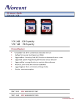
Figure 1-2: Stratix V Transceiver Native PHY IP Core
PLLs
PMA
altera _xcvr_native_ <dev>
Transceiver Native PHY
Transceiver
Reconfiguration
Controller
Reconfiguration to XCVR
Reconfiguration from XCVR
TX and RX Resets
Calilbration Busy
PLL and RX Locked
RX PCS Parallel Data
TX PCS Parallel Data
CDR Reference Clock
(when neither PCS is enabled)
TX PLL Reference Clock
Serializer/
Clock
Generation
Block
RX Serial Data
to
FPGA fabric
Transceiver
PHY Reset
Controller
TX PMA Parallel Data
RX PMA Parallel Data
TX Serial Data
Serializer
Deserializer
Standard
PCS
(optional)
10G PCS
(optional)
As shown, the Stratix V Native PHY connects to the separately instantiated Transceiver Reconfiguration
Controller and Transceiver PHY Reset Controller.
Table 1-1: Native Transceiver PHY Datapaths
Datapaths Stratix V Arria V Arria V GZ Cyclone V
PMA Direct:
This datapath connects the
FPGA fabric directly to the
PMA, minimizing latency.
You must implement any
required PCS functions in the
FPGA fabric.
(1)
Yes Yes Yes -
(1)
PMA Direct mode is supported for Arria V GT, ST, and GZ devices, and for Stratix V GT devices only.
UG-01080
2015.01.19
Native Transceiver PHYs
1-3
Introduction to the Protocol-Specific and Native Transceiver PHYs
Altera Corporation
Send Feedback

Datapaths Stratix V Arria V Arria V GZ Cyclone V
Standard:
This datapath provides a
complete PCS and PMA for
the TX and RX channels. You
can customize the Standard
datapath by enabling or
disabling individual modules
and specifying data widths.
Yes Yes Yes Yes
10G:
This is a high performance
datapath. It provides a
complete PCS and PMA for
the TX and RX channels. You
can customize the 10G
datapath by enabling or
disabling individual modules
and specifying data widths.
Yes - Yes -
Related Information
• Analog Settings for Arria V Devices on page 19-2
• Analog Settings for Arria V GZ Devices on page 19-11
• Analog Settings for Cyclone V Devices on page 19-26
• Analog Settings for Stratix V Devices on page 19-34
Non-Protocol-Specific Transceiver PHYs
Non-protocol specific transceiver PHYs provide more flexible settings than the protocol-specific
transceiver PHYs. They include the Custom PHY, Low Latency PHY, and Deterministic Latency PHY IP
Cores.
These PHYs include an Avalon
®
Memory-Mapped (Avalon-MM) interface to access control and status
registers and an Avalon Streaming (Avalon-ST) interface to connect to the MAC for data transfer.
Related Information
• Custom PHY IP Core on page 9-1
• Deterministic Latency PHY IP Core on page 11-1
• Low Latency PHY IP Core on page 10-1
Transceiver PHY Modules
The following sections provide a brief introduction to the modules included in the transceiver PHYs.
1-4
Non-Protocol-Specific Transceiver PHYs
UG-01080
2015.01.19
Altera Corporation
Introduction to the Protocol-Specific and Native Transceiver PHYs
Send Feedback

PCS
The PCS implements part of the physical layer specification for networking protocols. Depending upon
the protocol that you choose, the PCS may include many different functions. Some of the most commonly
included functions are: 8B/10B, 64B/66B, or 64B/67B encoding and decoding, rate matching and clock
compensation, scrambling and descrambling, word alignment, phase compensation, error monitoring,
and gearbox.
PMA
The PMA receives and transmits differential serial data on the device external pins. The transmit (TX)
channel supports programmable pre-emphasis and programmable output differential voltage (VOD). It
converts parallel input data streams to serial data. The receive (RX) channel supports offset cancellation to
correct for process variation and programmable equalization. It converts serial data to parallel data for
processing in the PCS. The PMA also includes a clock data recovery (CDR) module with separate CDR
logic for each RX channel.
Avalon-MM PHY Management Interface
You can use the Avalon-MM PHY Management module to read and write the control and status registers
in the PCS and PMA for the protocol-specific transceiver PHY. The Avalon-MM PHY Management
module includes both Avalon-MM master and slave ports and acts as a bridge. It transfers commands
received from an embedded controller on its slave port to its master port. The Avalon-MM PHY
management master interface connects the Avalon-MM slave ports of PCS and PMA registers and the
Transceiver Reconfiguration module, allowing you to manage these Avalon-MM slave components
through a simple, standard interface. (Refer to Transceiver PHY Top-Level Modules.)
Transceiver Reconfiguration Controller
Altera Transceiver Reconfiguration Controller dynamically reconfigures analog settings in Arria V,
Cyclone V, and Stratix V devices.
Reconfiguration allows you to compensate for variations due to process, voltage, and temperature (PVT)
in 28-nm devices. It is required for Arria V, Cyclone V, and Stratix V devices that include transceivers.
For more information about the Transceiver Reconfiguration Controller, refer to Transceiver Reconfigu‐
ration Controller IP Core. The reset controller may be included in the transceiver PHY or may be a
separately instantiated component as described in Transceiver PHY Reset Controller.
Related Information
Transceiver Reconfiguration Controller IP Core Overview on page 16-1
Resetting the Transceiver PHY
This section provides an overview of the embedded reset controller and the separately instantiated
Transceiver PHY Reset Controller IP Core.
The embedded reset controller ensures reliable transceiver link initialization. The reset controller initial‐
izes both the TX and RX channels. You can disable the automatic reset controller in the Custom, Low
Latency Transceiver, and Deterministic Latency PHYs. If you disable the embedded reset controller, the
powerdown, analog and digital reset signals for both the TX and RX channels are top-level ports of the
transceiver PHY. You can use these ports to design a custom reset sequence, or you can use the Altera-
provided Transceiver Reset Controller IP Core.
UG-01080
2015.01.19
Transceiver Reconfiguration Controller
1-5
Introduction to the Protocol-Specific and Native Transceiver PHYs
Altera Corporation
Send Feedback

The Transceiver PHY Reset Controller IP Core handles all reset sequencing of the transceiver to enable
successful operation. Because the Transceiver PHY Reset Controller IP is available in clear text, you can
also modify it to meet your requirements. For more information about the Transceiver PHY Reset
Controller, refer to Transceiver Reconfiguration Controller IP Core.
To accommodate different reset requirements for different transceivers in your design, instantiate
multiple instances of a PHY IP core. For example, if your design includes 20 channels of the Custom PHY
IP core with 12 channels running a custom protocol using the automatic reset controller and 8 channels
requiring manual control of RX reset, instantiate 2 instances of the Custom PHY IP core and customize
one to use automatic mode and the other to use your own reset logic. For more information, refer to
“Enable embedded reset control” in Custom PHY General Options.
For more information about reset control in Stratix V devices, refer to Transceiver Reset Control in Stratix
V Devices in volume 3 of the Stratix V Device Handbook. For Stratix IV devices, refer to Reset Control and
Power Down in volume 4 of the Stratix IV Device Handbook. For Arria V devices, refer to Transceiver
Reset Control and Power-Down in Arria V Devices. For Cyclone V devices refer to Transceiver Reset
Control and Power Down in Cyclone V Devices.
Related Information
• General Options Parameters on page 9-3
• Transceiver PHY Reset Controller IP Core on page 17-1
• Transceiver Reset Control in Stratix V Devices
• Reset Control and Power Down
• Transceiver Reset Control and Power-Down in Arria V Devices
• Transceiver Reset Control and Power Down in Cyclone V Devices
Running a Simulation Testbench
When you generate your transceiver PHY IP core, the Quartus
®
II software generates the HDL files that
define your parameterized IP core. In addition, the Quartus II software generates an example Tcl script to
compile and simulate your design in ModelSim.
1-6
Running a Simulation Testbench
UG-01080
2015.01.19
Altera Corporation
Introduction to the Protocol-Specific and Native Transceiver PHYs
Send Feedback

Figure 1-3: Directory Structure for Generated Files
<instance_name> _sim/synopsys -
Simulation files for Synopsys simulation tools
<project_dir>
<project_dir>/<instance_name> - includes PHY IP Verilog HDL and
SystemVerilog design files for synthesis
<instance_name>. v or .vhd - the parameterized transceiver PHY IP core
<instance_name> .qip - lists all files used in the transceiver PHY IP design
<instance_name> .bsf - a block symbol file for you transceiver PHY IP core
<instance_name> _sim/altera_xcvr <PHY_IP_name> - includes plain text
files that describe all necessary files required for a successful simulation. The
plain text files contain the names of all required files and the correct order
for reading these files into your simulation tool.
<instance_name> _sim/aldec -
Simulation files for Riviera-PRO simulation tools
<instance_name> _sim/cadence -
Simulation files for Cadence simulation tools
<instance_name> _sim/mentor -
Simulation files for Mentor simulation tools
The following table describes the key files and directories for the parameterized transceiver PHY IP core
and the simulation environment which are in clear text.
Table 1-2: Transceiver PHY Files and Directories
File Name Description
<project_dir> The top-level project directory.
<instance_name> .v or .vhd The top-level design file.
<instance_name> .qip A list of all files necessary for Quartus II compila‐
tion.
<instance_name> .bsf A Block Symbol File (.bsf) for your transceiver
PHY.
<project_dir>/<instance_name>/ The directory that stores the HDL files that define
the protocol-specific PHY IP core. These files are
used for synthesis.
UG-01080
2015.01.19
Running a Simulation Testbench
1-7
Introduction to the Protocol-Specific and Native Transceiver PHYs
Altera Corporation
Send Feedback

File Name Description
sv_xcvr_native.sv Defines the transceiver. It includes instantiations of
the PCS and PMA modules and Avalon-MM PHY
management interface.
stratixv_hssi_ <module_name> _rbc. sv These files perform rule based checking for the
module specified. For example, if the PLL type, data
rate, and FPGA fabric transceiver interface width
are not compatible, the checker reports an error.
altera_wait_generate.v Generates waitrequest for protocol-specific
transceiver PHY IP core that includes backpressure.
alt_reset_ctrl_tgx_cdrauto.sv Includes the reset controller logic.
<instance_name> _phy_assignments.qip Includes an example of the PLL_TYPE assignment
statement required to specify the PLL type for each
PLL in the design. The available types are clock
multiplier unit (CMU) and auxiliary transmit
(ATX).
<project_dir>/<instance_name> _sim/ altera_xcvr_
<PHY_IP_name>/
The simulation directory.
<project_dir>/<instance_name>_sim/ aldec Simulation files for Riviera-PRO simulation tools.
<project_dir>/<instance_name>_sim/ cadence Simulation files for Cadence simulation tools.
<project_dir>/<instance_name>_sim/ mentor Simulation files for Mentor simulation tools.
<project_dir>/<instance_name>_sim/ synopsys Simulation files for Synopsys simulation tools.
The Verilog and VHDL transceiver PHY IP cores have been tested with the following simulators:
• ModelSim SE
• Synopsys VCS MX
• Cadence NCSim
If you select VHDL for your transceiver PHY, only the wrapper generated by the Quartus II software is in
VHDL. All the underlying files are written in Verilog or System Verilog. To enable simulation using a
VHDL-only ModelSim license, the underlying Verilog and System Verilog files for the transceiver PHY
are encrypted so that they can be used with the top-level VHDL wrapper without using a mixed-language
simulator.
For more information about simulating with ModelSim, refer to the Mentor Graphics ModelSim Support
chapter in volume 3 of the Quartus II Handbook.
The transceiver PHY IP cores do not support the NativeLink feature in the Quartus II software.
Generating Custom Simulation Scripts for Multiple Transceiver PHYs with ip-make-simscript
Use the ip-make-simscript utility to generate simulation command scripts for multiple transceiver
PHYs or Qsys systems. Specify all Simulation Package Descriptor files (.spd). The .spd files list the
required simulation files for the corresponding IP core. The MegaWizard Plug-In Manager and Qsys
generate the .spd files.
1-8
Running a Simulation Testbench
UG-01080
2015.01.19
Altera Corporation
Introduction to the Protocol-Specific and Native Transceiver PHYs
Send Feedback

When you specify multiple .spd files, the ip-make-simscript utility generates a single simulation script
containing all required simulation information. The default value of TOP_LEVEL_NAME is the
TOP_LEVEL_NAME defined in the IP core or Qsys .spd file. If this is not the top-level instance in your
design, specify the top-level instance of your testbench or design.
You can set appropriate variables in the script or edit the variable assignments directly in the script. If the
simulation script is a Tcl file that can be sourced in the simulator, set the variables before sourcing the
script. If the simulation script is a shell script, pass in the variables as command-line arguments to shell
script.
To run ip-make-simscript , type the following at the command prompt:
<ACDS installation path>\quartus\sopc_builder\bin\ip-make-simscript
The following tables lists some of the options available with this utility.
Table 1-3: Options for the ip-make-simscript Utility
Option Description Status
--spd=<file>
Describes the list of compiled files and
memory model hierarchy. If your design
includes multiple IP cores or Qsys systems
that include .spd files, use this option for each
file. For example:
ip-make-simscript --spd=ip1.spd --
spd=ip2.spd
Require
d
--output-
directory=<directory>
Directory path specifying the location of
output files. If unspecified, the default setting
is the directory from which ip-make-
simscript is run.
Option
al
--compile-to-work
Compiles all design files to the default work
library. Use this option only if you encounter
problems managing your simulation with
multiple libraries.
Option
al
--use-relative-paths Uses relative paths whenever possible Option
al
To learn about all options for the ip-make-simscript , type the following at the command prompt:
<ACDS installation path>\quartus\sopc_builder\bin\ip-make-simscript --help
Related Information
• Mentor Graphics ModelSim Support
• Simulating Altera Designs
Unsupported Features
The protocol-specific and native transceiver PHYs are not supported in Qsys in the current release.
UG-01080
2015.01.19
Unsupported Features
1-9
Introduction to the Protocol-Specific and Native Transceiver PHYs
Altera Corporation
Send Feedback
/