Page is loading ...

Recirculating KIT
PRO Hoods
Applicable models:
PRO001MX 30
PRO001MX 36
LI295A
1

WARNING:
• Read and Save These Instructions.
• Approved for Residential Appliances only.
• PLEASE READ ENTIRE INSTRUCTIONS BEFORE PROCEEDING.
• INSTALLER: Please leave these Instructions with this unit for the owner.
• OWNER: Please retain these instructions for future reference.
• Turn off power circuit at service panel and lock out panel before installing this kit to the appliance.
• Installation must comply with all local codes.
PACKAGING CONTENTS
• Air deflector
• 3 Charcoal Filters
• 12 springs
• Mounting hardware
BEFORE INSTALLING THE RECIRCULATING KIT
The recirculation kit installation affects the hood installation, so take in consideration the following steps.
Cabinet or ceiling preparation when installing the recirculation kit
For cabinet or ceiling preparation take in consideration that there is no need to provide cutouts on walls for
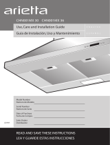
vertical or rear air discharge, since there is no need to install any duct work. See the figure 1 for conduit
passage cut-out. See figure 2 for air passage cut-out on hood.
Cabinet
front
3-1/8” x 2-1/3”
Cut out for
conduit
passage
A
Bottom of
cabinet or
soffit
12” min
27/32”
Real
wall
Center
line
Hood width min.
Figure 1. Conduit Passage Cutout
Note: The height of the hood with the recirculation kit installed, increases from 18" to 22“. Check that
there is enough clearance and that minimum height from the countertop to the bottom of the hood is
24” minimum for electric ranges to 30” minimum for gas ranges.
2

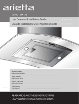
Figure 2.
Air passage cut-out on hood
Hood Preparation
• The hood transition must not be installed, since no ductwork is necessary, if it is installed, remove
the transitions.
• Attach two pins B on top of the hood. See Figure 2. Make sure a Gap exists between the hood and
the hood surface.
Wall Mount Installation
First install the deflector on top of the hood, then install to the wall:
1) Attach four screws C on bottom of the deflector, do not tight completely, and leave approximately ¼”
from the bottom of the air deflector to the screw head. See Figure 2.
2) Install the deflector on top of the hood so that screws C and pins B go respectively into the existing side
slots at the top of the hood and the existing side slots at the bottom of the deflector (See Figure 2), slide
deflector frontward until it mechanically stops.
3) Tighten the four screws C from the inside of the hood.
4) Attach screws D from inside the hood through points E to attach the air deflector to the hood (see
Figure 2, number depends on hood size).
5) Proceed to install hood as described on the hood manual.
Installation under Cabinet
First install the deflector under the cabinet, and then install Hood to the air deflector:
1) Find the centerline at the bottom of the cabinet. Draw a line along this centerline from rear to the front of
the cabinet.
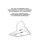
2) Draw two lines, one at a 1-1/2” of distance from the wall, then other at a 9-1/16“ distance from the
previous line. Identify and mark 4 points for the screw locations, divide by two the distance W, and
measure the obtained distance from the center line to the left and right sides, mark the points (see
Figure 3).
3) Attach 4 screws at the bottom of the cabinet (screws not supplied) do not tight completely; leave a
space of 1/2” from cabinet bottom surface and screw heads. Note: the screws must be able to support
the hood and deflector weight, and must be the right type according with the bottom cabinet surface.
4) Hang the deflector at the screws through the side slots present in the deflector top. Tight the four
screws through slots F. See Figure 2.
5) Attach four screws C at the bottom of the deflector, do not tight completely. See Figure 2.
6) Install the hood at the bottom of the air deflector so that screws C and pins B go respectively into the
existing side slots at the top of the hood and the existing side slots at the bottom of the air deflector
(See Figure 2), slide the hood rearward until it stops.
7) Remove 1 of 2 knockouts and install 1/2“conduit connector in j-box.
8) Attach screws, from inside of the hood through point E to final assembly Deflector to the hood (see
Figure 2, number depends on hood size).
3

Proceed to install hood as described in the Installation manual.
W
9-1/16”
1-1/2”
Center
Line
Screw for
cabinet bottom
installation
Figure 3. Marks in the cabinet
CHARCOAL FILTER INSTALLATION
• Position the charcoal filter over the grease filter and insert the 4 springs (to prevent the movement).
• Reinstall the grease filter onto the bottom of the hood.
Note: After 120 functional hours the charcoal filter must be replaced.
4
/