Page is loading ...

MAN102 Rev Date 8/19/2008
a
SERIMUX-TERM-CS-16/8
Terminal Converter with
Console Switch
Installation and Operation Manual
SERIMUX
®
Series

i
TRADEMARK
SERIMUX is a registered trademark of Network Technologies Inc in the U.S. and other countries.
COPYRIGHT
Copyright © 2003, 2008 by Network Technologies Inc. All rights reserved. No part of this publication may be reproduced, stored
in a retrieval system, or transmitted, in any form or by any means, electronic, mechanical, photocopying, recording, or otherwise,
without the prior written consent of Network Technologies Inc, 1275 Danner Drive, Aurora, Ohio 44202.
CHANGES
The material in this guide is for information only and is subject to change without notice. Network Technologies Inc reserves the
right to make changes in the product design without reservation and without notification to its users.

ii
TABLE OF CONTENTS
INTRODUCTION.............................................................................................................................................................1
Terminal Converter ...................................................................................................................................................... 1
Console Switch ............................................................................................................................................................ 2
MATERIALS.................................................................................................................................................................... 3
FEATURES AND FUNCTIONS ...................................................................................................................................... 4
1. INSTALLATION .......................................................................................................................................................... 5
1.1 Rack Mounting Instructions ................................................................................................................................... 5
1.2 TERMINAL vs. SERIMUX Cable Connections...................................................................................................... 6
1.3 Connect Devices, Hosts, and Power..................................................................................................................... 6
1.4 Connect the SERIMUX and TERMINAL to a Network .........................................................................................7
1.5 Connect the Monitor and Keyboard....................................................................................................................... 7
1.6 Power Up The SERIMUX-TERM-CS-16 ............................................................................................................... 7
2. GETTING STARTED .................................................................................................................................................. 8
2.1 Setup The TERMINAL........................................................................................................................................... 8
2.1.1 Entering TERMINAL Setup.............................................................................................................................. 8
2.1.2 Setup Directory ................................................................................................................................................ 8
2.1.3 Changing The TERMINAL Operating Parameters .......................................................................................... 8
F2- Genrl SETUP Menu ........................................................................................................................................ 9
F4- Comm SETUP Menu....................................................................................................................................... 9
2.1.4 Saving and Exiting Setup................................................................................................................................. 9
2.2 Connect to the SERIMUX......................................................................................................................................9
3. USING THE SERIMUX CONSOLE SWITCH ........................................................................................................... 11
3.1 Administrator Controls ........................................................................................................................................ 12
3.1.1 Login as the administrator ............................................................................................................................. 12
3.1.2 Port List..........................................................................................................................................................13
3.1.3 Port Settings ..................................................................................................................................................14
3.1.3.1 Port serial settings ................................................................................................................................... 16
3.1.3.2 Modem settings ....................................................................................................................................... 18
3.1.3.3 Port data buffer........................................................................................................................................ 19
3.1.3.4 Clear Port data buffer .............................................................................................................................. 19
3.1.4 User List.........................................................................................................................................................20
3.1.5 User Settings .................................................................................................................................................21
3.1.5.1 Port access.............................................................................................................................................. 22
3.1.5.2 Copy User Settings.................................................................................................................................. 22
3.1.6 Advanced Settings.........................................................................................................................................23
3.1.6.1 Change administrator password.............................................................................................................. 23
3.1.6.2 Firmware.................................................................................................................................................. 24
3.2. User Controls...................................................................................................................................................... 26
3.2.1 User "Accessible host list" screen .................................................................................................................26
3.2.2 User main menu ............................................................................................................................................ 27
3.2.3 Port List screen..............................................................................................................................................28
3.2.4 User Terse mode ...........................................................................................................................................29
3.2.4.1 Terse mode commands........................................................................................................................... 29
3.2.5 System Reset button ..................................................................................................................................... 30
3.3 Firmware Upgrade ............................................................................................................................................... 31
KEYPAD CONTROL..................................................................................................................................................... 33
Functions of the Keypad............................................................................................................................................ 33
Login the administrator ........................................................................................................................................... 33
Disconnect the administrator or a user with administrative privileges.................................................................... 34
Login a user to the administrator main menu .........................................................................................................34
Login user to a port.................................................................................................................................................34
Login user to a port and connect the user port to a host port................................................................................. 35
Disconnect and logout a user ................................................................................................................................. 35
Connect 2 host ports............................................................................................................................................... 35

iii
Disconnect 2 ports .................................................................................................................................................. 36
Attach or detach a modem......................................................................................................................................36
Reset SERIMUX Console Switch to default settings.................................................................................................36
4. USING THE TERMINAL ........................................................................................................................................... 37
4.1 How To Setup The TERMINAL ........................................................................................................................... 37
4.1.1 Entering TERMINAL Setup............................................................................................................................37
4.1.2 Saving and Exiting Setup...............................................................................................................................37
4.1.3 Setup Directory .............................................................................................................................................. 37
4.2 Changing The TERMINAL Operating Parameters .............................................................................................. 38
F1- Disp SETUP Menu .......................................................................................................................................... 38
F2- Genrl SETUP Menu..........................................................................................................................................38
F3- Keybd SETUP Menu ........................................................................................................................................ 39
F4- Comm SETUP Menu........................................................................................................................................ 39
F5- Misc SETUP Menu ...........................................................................................................................................40
F6-Tabs SET-UP Menu ..........................................................................................................................................40
F7- FKeys SET-UP Definition Setup Menu ............................................................................................................ 40
F8- Ansbk SET-UP Menu ....................................................................................................................................... 41
F9- Lan Setup Menu ...............................................................................................................................................41
F10- Colr1 Set-up Menu ......................................................................................................................................... 41
F11- Colr2 Set-up Menu ......................................................................................................................................... 42
4.3 Local Keyboard Commands ................................................................................................................................ 45
4.4 TERMINAL Command Guide .............................................................................................................................. 46
4.4.1 Commands Supported in ASCII Personalities............................................................................................... 46
4.4.2 Variable Values for Table 8 Commands........................................................................................................ 53
4.5 ANSI Command Guide ....................................................................................................................................... 57
4.5.1 VT100, VT220 and Console ANSI Command Guide .................................................................................... 57
4.5.2 VT52 Command Guide ..................................................................................................................................64
4.6 Using Printer Server via Ethernet Connection..................................................................................................... 65
4.6.1 Basic Setup....................................................................................................................................................65
4.6.2 Setup for LPD ................................................................................................................................................66
4.6.3 LPD printing ................................................................................................................................................... 67
4.6.4 Setup for TFTP .............................................................................................................................................. 67
4.6.5 TFTP Printing................................................................................................................................................. 67
5. HARDWARE INFORMATION...................................................................................................................................68
5.1 Hardware Specifications: TERMINAL..................................................................................................................68
5.2 Hardware Specifications: SERIMUX ................................................................................................................... 68
5.3 CPU-to-RACKMUX Ethernet Crossover Cable ................................................................................................... 69
5.4 Serial Port Cabling...............................................................................................................................................69
5.5 Serial Port Pinouts ............................................................................................................................................... 69
5.6 Cable Adapters.................................................................................................................................................... 70
5.7 TERMINAL Connector Pin Assignments ............................................................................................................. 72
INDEX............................................................................................................................................................................74
WARRANTY INFORMATION ....................................................................................................................................... 74

iv
TABLE OF FIGURES
Figure 1- Mount Switch in a Rack ......................................................................................................................................................5
Figure 2- Distinction of connections between TERMINAL and SERIMUX .........................................................................................6
Figure 3- Connect serial devices, printer, and power cord.................................................................................................................6
Figure 4- Connect to a Local Area Network (LAN).............................................................................................................................7
Figure 5- Connect User's Monitor and Keyboard ..............................................................................................................................7
Figure 6- Fields in the Setup menu display which function keys to press for submenus ...................................................................8
Figure 7- Startup- Accessible host list .............................................................................................................................................10
Figure 8- Administrator main menu..................................................................................................................................................12
Figure 9- The Port list displays the status of all ports ......................................................................................................................13
Figure 10- The Port settings menu ..................................................................................................................................................14
Figure 11- Control Codes for in-band disconnect sequence ............................................................................................................15
Figure 12- Port serial settings menu ................................................................................................................................................16
Figure 13- Modem settings menu ....................................................................................................................................................18
Figure 14- Port data buffer...............................................................................................................................................................19
Figure 15- User List .........................................................................................................................................................................20
Figure 16- User settings menu......................................................................................................................................................... 21
Figure 17- Port access list for User 01............................................................................................................................................. 22
Figure 18- Administrator's Advanced settings menu........................................................................................................................23
Figure 19- Firmware menu............................................................................................................................................................... 24
Figure 20- The SERIMUX is waiting to save its firmware.................................................................................................................25
Figure 21- A user with limited host port access ...............................................................................................................................26
Figure 22- User main menu .............................................................................................................................................................27
Figure 23- A limited user accessible Port list ...................................................................................................................................28
Figure 24- User port in Terse mode.................................................................................................................................................29
Figure 25- Location of Restore Defaults button ............................................................................................................................... 30
Figure 26- Firmware upload window ................................................................................................................................................31
Figure 27- Type "AT" to auto-detect baud rate ................................................................................................................................31
Figure 28- Last confirmation before firmware update ......................................................................................................................32
Figure 29- File transfer in progress..................................................................................................................................................32
Figure 30- Keypad and LEDs...........................................................................................................................................................33
Figure 31- Fields in the Setup menu display which function keys to press for submenus ............................................................... 37
List of Tables
Table 1- Main Setup Menu (F12) Exit Functions................................................................................................................................9
Table 2- Main Setup Menu (F12) Exit Functions..............................................................................................................................37
Table 3- Programmable Keys .......................................................................................................................................................... 41
Table 4- Color Setup Menu.............................................................................................................................................................. 42
Table 5- Color Palettes ....................................................................................................................................................................43
Table 6- Local Keyboard Commands in Native Mode...................................................................................................................... 45
Table 7- Commands Supported in ASCII Personalities ...................................................................................................................46
Table 8- VT52 Mode Escape Sequences ........................................................................................................................................64

NTI RACK MOUNT CONSOLE TERMINAL WITH CONSOLE SWITCH
1
INTRODUCTION
The SERIMUX-TERM-CS-x (x=8 or 16) combines a 8 or 16 port Console Switch (SERIMUX) and a VT100/ANSI Terminal
Converter (TERMINAL) in a single package controlled by a PS/2 keyboard and VGA monitor. The Console Switch uses menu-
driven integrated software. The SERIMUX-TERM-CS-16 can control of up to 16 serial devices including servers, switches,
routers, and telecom gear. Additional control methods include front panel keypad, LAN or dial-up modem connections. It enables
unlimited access to remote network management, providing optimum system performance and availability.
Terminal Converter
The Terminal Converter (TERMINAL) is easy to install and configure for either of the following communication modes:
¾ RS232 Terminal (using an RS-232 port for serial console connection). Use this configuration of the Console Terminal with
the Console Switch to control multiple servers.
¾ Telnet Terminal (using an RJ45 10/100 Base-T network port for Ethernet telnet console connection). The Ethernet
connection can be used with any 10/100Mbps-compatible Ethernet host adapter, but is most suited for use with SUN RSC
(Remote System Control) Ethernet ports, since these provide the same functionality as serial (ttya) console ports. This
connection supports up to 12 telnet sessions to different servers. The state of each server session is preserved by the
terminal. Terminal sessions can be switched via hot-keys. When using the Ethernet telnet connection, the Terminal Drawer
can be connected to multiple servers via an Ethernet switch. However, it is advisable that the network used to connect the
server consoles remains private for security reasons.
Note: Both RS232 serial and Ethernet telnet connections cannot be active at the same time.
The TERMINAL is a general purpose character terminal converter offering full transaction capabilities and is largely pre-configured
for most applications. It was designed in conjunction with SUN Microsystems to ensure flawless compatibility with all SUN servers.
Features
• High-quality metal construction (ideal for most industrial and commercial settings)
• Supports RSC capabilities.
• Supports parallel and RS232 serial printers
• Printer server capability.
• Converts the RS232 port of a serial device to PS/2 keyboard and VGA ports so the device can be operated by an NTI
KVM switch.
• ASCII text is displayed on the VGA monitor.
• Supports color display functions in 80 and 132 column mode.
• 1RU rackmount case is standard.
• Connects to 10BaseT Ethernet port
Multiple RS-232 Emulations:
• ADDS A2 • TV1925 • WY-60
• PC TERM • VT52 • WY-100
• PCG Alpha • VT100 • WY-120
• Console ANSI • VT220 • WY-325
• TVI910+ • WY-50+

NTI RACK MOUNT CONSOLE TERMINAL WITH CONSOLE SWITCH
2
Console Switch
The Console Switch (SERIMUX) includes a text-based menu for easy connection management for administrators. Using a
terminal emulator the menu provides a quick means for user serial connection changes and device control.
The Console Switch (SERIMUX) is a serial port router that allows links (or connections) between multiple pairs of RS-232
asynchronous serial ports. The main purpose of the switch is to enable users to manage several serial devices from local or
remote locations (using external modems). Devices include routers, DSU's, servers, switches or any other equipment allowing
serial operation using RS232 interface. Users can work locally (using the integral TERMINAL) or from remote locations.
Each SERIMUX port has to be configured for serial communication (baud rate, parity, etc) within the specifications of the attached
serial device, but the configurations of the two devices linked by the SERIMUX do not need to match. Various parameters
(communication speed, hardware and/or software flow control, timeout, etc) can be selected for each SERIMUX port. Devices
may be either locally connected or connected through attached modems.
Each SERIMUX port can be configured as either a host or user port. Serial hosts (such as servers, switches etc.) are connected to
host ports, while serial user devices (such as a terminal or serial console) are connected to user ports.
The SERIMUX Console Switch supports two operator levels: user and administrator. Users login at user ports and connect to
serial devices attached at host ports. The administrator (logged in at any user port) and users with administrative privileges can
connect to serial devices attached to host ports and see and/or modify various port or user parameters.
Features
The SERIMUX provides secure, flexible management of servers, routers, switches, and other networked devices. Key features
include:
• Eliminates the need to connect each device to an ASCII terminal or PC
• Connect up to 16 devices with different baud rates, parity, and character length.
• Provides out-of-band access to network devices (servers, routers, network switches, and any other network devices
allowing console operation using RS232)
• No inadvertent "break" signals are generated to cause unintentional rebooting of SUN computers
• Two operator levels (administrator and user)
• Switching is simplified with programmable device names and menu-driven device selection
• Built-in data buffers save the most recent RS232 console output from each connected device, which simplifies
troubleshooting failures
• The SERIMUX can be power cycled without halting a SUN host computer
• Gain access to servers without interrupting service to end-users; maintain optimal up-time
• Manage server farms or data centers via serial ports and standard external modems
• Connects to console serial ports using standard CAT5/5e/6 cables and cable adapters.
o Maximum cable length is 100 feet.

NTI RACK MOUNT CONSOLE TERMINAL WITH CONSOLE SWITCH
3
MATERIALS
Materials Supplied with the NTI SERIMUX-TERM-CS16 Terminal Converter with Console Switch:
+6
Manual CD
Materials Not Supplied, but REQUIRED:
Serial cable with at least one RJ45 male end for connection to the Console Switch from each device to be connected. See “Serial
Port Pinouts” on page 69 for cable pinout.
IEC Powercord (country specific)
DB25M-RJ45F-C
Modem Adapter
DB9F-RJ45F
Serial Adapter
RJ45F-T
–
DB25M
Console Adapter
DB25F- RJ45F
Console Adapter
4- #10-32x3/4” screws
and cage nuts

NTI RACK MOUNT CONSOLE TERMINAL WITH CONSOLE SWITCH
4
FEATURES AND FUNCTIONS
1. Power LED- indicates operation status
Green=Power-On, Video Input Signal OK
Red = Suspend / Stand-by, or no Video Input Signal
2. Port LEDs- LEDs will illuminate to indicate active administrator port and data traffic; also used to indicate port or user number
when entering commands from the keypad.
3. Command LEDs- LEDs will illuminate to indicate functions being performed
4. Keypad- for manual control of switch functions
5. Power- IEC Power Socket- for connection of AC power cord
6. Switch- for powering the SERIMUX On/Off
7. RJ45 Connectors- for attaching CAT5 cables from serial devices
8. Keyboard- for connecting the user keyboard
9. Monitor- for connecting the user monitor
10. Serial -Male DB9 connector- for attaching a local printer serially
11. Parallel- Female DB25 connector- for attaching local printer with parallel printer cable
12. Terminal-10/100 Base T-RJ45 Connector for 10/100 Mbps communications- for TERMINAL connection to Ethernet
13. System Reset- button to cycle power to the SERIMUX and TERIMINAL without powering down the SERIMUX
14. ISP Button- For use when restoring the firmware in the SERIMUX (factory use only)
RESET
9
101112
131415
123
4
5
6
78
NTI
NETWORK
TECHNOLOGIES
INCORPORATED
Te l: 33 0- 5 62- 70 70
Fax:330-562-1999
1275 Danner Dr
Aurora, OH 44202
www.networktechinc.com
R
MONI TOR
KEYBOARD
TERMINAL-
10 BASE T
ISP
PARALLEL
SERIAL
PRINTER
16
Front and Rear Views of SERIMUX-TERM-CS-16
2
3
4
1
0 234 5678
9
1
10 11 12 13 14 15 16
PWR
18 19 20 21 22 23
24 25
17
26 27 28 29 30 31
32
ESC
ADMIN USER
PORT
6
12345ENTER
DISCON
7890Discon
User
Admin
Port
SERIMUX
R
NTI
R
Network Techn ologies I nc
56
7
8
910 11 12 1314

NTI RACK MOUNT CONSOLE TERMINAL WITH CONSOLE SWITCH
5
1. INSTALLATION
1.1 Rack Mounting Instructions
This NTI switch was designed to be directly mounted in a rack and includes a mounting flange to make attachment easy.
Install 4 cage nuts (supplied) to the rack in locations that line up with the holes (or slots) in the mounting flange on the NTI switch.
Then secure the NTI switch to the rack using four #10-32 x3/4” screws (supplied). Each screw should be of sufficient length to
go completely through the NTI mounting flange, rack frame and fully engage all threads in the captive nut. Be sure to tighten all
mounting screws securely.
Do not block power supply vents in the NTI switch chassis (if provided). Be sure to enable adequate airflow in front of and
behind the NTI switch.
Attach all cables securely to the switch and where necessary supply adequate means of strain relief for cables.
Figure 1- Mount Switch in a Rack
Cage Nuts
Rack Screws
Rack
(supplied)
#10-32x3/4"
(supplied)

NTI RACK MOUNT CONSOLE TERMINAL WITH CONSOLE SWITCH
6
1.2 TERMINAL vs. SERIMUX Cable Connections
The connectors on the rear of the SERIMUX-TERM-CS-16 are split between those for the TERMINAL connections, and those for
the SERIMUX connections (see Figure 2).
Figure 2- Distinction of connections between TERMINAL and SERIMUX
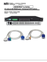
1.3 Connect Devices, Hosts, and Power
1. Connect each serial device (or host) to be connected by the SERIMUX to any port labeled "1" through "16" using a DTE
or DCE type serial cable. It may be necessary to add one of the cable adapters (supplied) detailed in "Cable Adapters"
(page 70) between the device port on the serial device (or host) and the RJ45 connector.
Note: There are two types of serial devices, 1) data communication equipment (DCE)(i.e. modem) and 2) data terminal
equipment (DTE) (i.e. CPU), each having different connector pin assignments. The cable adapters (see “Materials” on
page 3) make the proper connections.
2. If connecting a printer, connect either a serial printer cable to the remaining male DB9 connector or a parallel printer
cable to the female DB25 connector (see Figure 3).
3. Connect the powercord to the IEC power connector.
Figure 3- Connect serial devices, printer, and power cord
ET HERN ET
RESET
9
10
1112
131415 1234
5
6
78
NTI
NETWORK
TECHNOLOGIES
INCORPORATED
Tel: 3 30-562 - 7070
Fax: 330 -562- 1 999
1275 Dan ner Dr
Auro ra, OH 4420 2
www.networktechinc.com
R
MONI T OR
KEYBOARD
TE RMI NAL-
10 BASE T
ISP
PARALLEL
SERIAL
PRINTER
16
Rear View of SERIMUX-TERM-CS-16
SERVER
ROUTER
FIREWALL
RJ45
Male
Connector
Ethernet cable
Attach local printer
either by parallel cable to "Parallel"
or by serial cable to "Serial"
PBX
IEC Power Connector
Powercord
RESET
9
10
1112
131415 1234
5
6
78
NTI
NETWORK
TECHNOLOGIES
INCORPORATED
Tel: 3 30-562 - 7070
Fax: 330 -562- 1 999
1275 Dan ner Dr
Auro ra, OH 4420 2
www.n etwor ktechin c.com
R
MONI T OR
KEYBOARD
TE RMI NAL-
10 BASE T
ISP
PARALLEL
SERIAL
PRINTER
16
Terminal Converter
(TERMINAL)
Console Switch
(SERIMUX)
Rear View of SERIMUX-TERM-CS-16

NTI RACK MOUNT CONSOLE TERMINAL WITH CONSOLE SWITCH
7
1.4 Connect the SERIMUX and TERMINAL to a Network
To control the SERIMUX and TERMINAL through a network connected PC, connect a CAT5 Ethernet network cable to the
connector marked "TERMINAL-10 BASE T". Then connect the other end of the Ethernet cable to a Local Area Network (LAN)
through a 10/100 BaseT switch or hub (see Figure 4).
Figure 4- Connect to a Local Area Network (LAN)
Alternatively, the TERMINAL may be directly connected to a PC using a CAT5 Crossover cable. See page 69 for specifications.
1.5 Connect the Monitor and Keyboard
Connect a VGA monitor and PS/2 keyboard to the connectors marked “MONITOR” and “KEYBOARD”.
Figure 5- Connect User's Monitor and Keyboard
1.6 Power Up The SERIMUX-TERM-CS-16
1. Connect the powercord to a power source and power-ON the SERIMUX using the switch on the rear of the
SERIMUX-TERM-CS-16.
2. Power-ON the connected VGA monitor.
RESET
9101112
131415
123
4
5
6
78
NTI
NETWORK
TECHNOLOGIES
INCORPORATED
Tel: 3 30-562 - 7070
Fax: 330 -562- 1 999
1275 Dan ner Dr
Auro ra, OH 4420 2
www.n etwor ktechin c.com
R
MONI T OR
KEYBOARD
TE RMI NAL-
10 BASE T
ISP
PARALLEL
SERIAL
PRINTER
16
PS/2 Keyboard
VGA
Multi-Scan
Monitor
VGA
Monitor
6 miniDIN
male connector
15HD male
video connector
Rear View of SERIMUX-TERM-CS-16
RJ45
Male
Connector
LAN
Ethernet cable
RESET
9
101112131415 1234
5
6
78
NTI
NETWORK
TECHNOLOGIES
INCORPORATED
Tel: 3 30-562 - 7070
Fax: 330 -562- 1 999
1275 Dan ner Dr
Auro ra, OH 4420 2
www.n etwor ktechin c.com
R
MONI T OR
KEYBOARD
TE RMI NAL-
10 BASE T
ISP
PARALLEL
SERIAL
PRINTER
16
Rear View of SERIMUX-TERM-CS-16
Network
Server
VGA
Multi-Scan
Monitor
Control Terminal

NTI RACK MOUNT CONSOLE TERMINAL WITH CONSOLE SWITCH
8
2. GETTING STARTED
Introduction
This chapter covers basic configuration topics. Included is information on setting up the TERMINAL to control the SERIMUX.
1. Using the instruction under “Setup The TERMINAL” below (or more detailed instruction on page 37), setup the TERMINAL to
make connection to the SERIMUX. Configure the terminal as follows:
• Ethernet Mode set to OFF (F4 menu)
• Baud rate at 9600 bps (F4 menu)
• 8 bits (F4 menu)
• no parity (F4 menu)
• 1 stop bit (F4 menu)
• no flow control (F4 menu)
• ANSI or VT100 terminal mode (F2 menu).
Within the SERIMUX firmware, the "CONSOLE" port is the internal connection between the TERMINAL and the
SERIMUX. For consistency, when Port 0 is mentioned within this manual, it refers to the connection made by the
TERMINAL.
2.1 Setup The TERMINAL
To control the SERIMUX some initial settings must be configured in the TERMINAL.
2.1.1 Entering TERMINAL Setup
Hold down the [ ALT] key and press the [ Esc] key to enter Setup mode. When entering Setup, any text on the screen temporarily
disappears, and the main SETUP directory appears (See Figure 6). When leaving the Setup mode, the main SETUP directory
disappears, and any text that was on the screen will reappear.
2.1.2 Setup Directory
The fields at the bottom of the screen show the various setup menus where the terminal's operating parameters can be changed
and the function key to press to immediately display any menu.
Figure 6- Fields in the Setup menu display which function keys to press for submenus
2.1.3 Changing The TERMINAL Operating Parameters
To select one of the setup menus shown, press the indicated function key.
- The screen for that menu appears with the name highlighted.
- The fields at the middle of the screen indicate the parameters that can be changed in that menu.
- The top line identifies the keys to press to highlight the parameter fields and change the settings.
The procedure is: (1) Use arrow key to highlight the parameter field to be changed.
(2) Use the Spacebar to change the parameter.
Pressing [F12> always returns the user to the top menu.

NTI RACK MOUNT CONSOLE TERMINAL WITH CONSOLE SWITCH
9
The following lists only what is necessary to connect to SERIMUX. For a complete list of features, see page 37.
F2- Genrl SETUP Menu
Personality set to Digital Equipment VT-100 or Console ANSI
F4- Comm SETUP Menu
Baud Rate set to 9600
Ethernet Mode set to OFF to set the communication routing by Serial Port.
Data / Stop Bits set to send and receive 8-bits data with one stop bit
Xmt Handshake set to None
Parity set to none
2.1.4 Saving and Exiting Setup
The first menu seen when entering Setup serves as a directory to the other Setup menus. To exit Setup or any submenu, press
[ F12]. Pressing [ F12] will return the display to the main Setup directory and with another press of [ F12] the user will exit
Setup.
The highlighted field at the right of the screen gives the user the choice of saving or not saving parameter changes into
memory before returning the TERMINAL to the normal operating mode. Settings changed will effect the operating environment
until the TERMINAL is powered-down. Setting changes will only be restored at power-up if they are saved before exiting Setup.
Note: If settings are not saved before exiting Setup, any new selections will be lost when the SERIMUX is powered-
down.
To save Setup selections
, depress the Spacebar to change the save field at the right side of the screen from NO to YES before
exiting Setup. (Table 1 describes your options for exiting Setup.)
Press [ F12] to leave Setup and return to the normal display mode.
Table 1- Main Setup Menu (F12) Exit Functions
Option Function
No Returns terminal to normal operating mode without saving parameters changes for power up
Yes
Saves all changes (operating parameter, tabs, key definition, and answerback message); returns terminal
To its normal operating mode.
Shift + Esc
Restores all setting (operating parameters, tabs, key definitions, and answerback message) to their factory
default values.
For changes to the TERMINAL settings to take effect, the RACKMUX must be power cycled. Disconnect power from the AC
adapter and reconnect.
2.2 Connect to the SERIMUX
1. Press [ Enter] on the keyboard to be recognized as the default SERIMUX user. The "Accessible host list" for "User01",
logged in at "Port00" will be displayed (see Figure 7). By default, all ports are configured as Host ports and all are accessible.
Note: If the user menu does not display, re-initialize the SERIMUX following the "Reset SERIMUX Console Switch to
default settings" instructions on page 36.

NTI RACK MOUNT CONSOLE TERMINAL WITH CONSOLE SWITCH
10
2. To connect to an attached CPU, enter the number of the port the CPU is connected to and press [ Enter].
Figure 7- Startup- Accessible host list

NTI RACK MOUNT CONSOLE TERMINAL WITH CONSOLE SWITCH
11
3. USING THE SERIMUX CONSOLE SWITCH
The SERIMUX-TERM-CS-16 is controlled using
• Terminal Control- using a connected keyboard, VGA Monitor and the built-in TERMINAL
• Serial Control- from a "dumb" terminal- locally-connected
- through an external modem from a remote location
• Keypad Control (reduced set of commands)
Terminal Control
The TERMINAL built-in to the SERIMUX-TERM-CS-16 can quickly provide access to the Console Switch (see page 8).
Serial Control
The SERIMUX Console Switch can be easily configured using serial communications from either a locally-connected “dumb”
terminal or from a terminal remotely connected through a modem. Using a keyboard-controlled menu, the user can modify
various parameters and options for each port. The administrator menu can be accessed by the administrator for full feature
control, or the user menu, by any user, for more restricted control of port connections.
Keypad Control
The keypad has direct control over basic SERIMUX functions. The keypad can be used to make changes to port connections
regardless of any menu control taking place. Command LEDs on the front panel of the SERIMUX Console Switch indicate the
status of the switch and what function is being performed. For more on Keypad Control, see page 33.
Note: The keypad will only work after first entering the assigned PIN number. See page 33 for more info.
The default keypad PIN number is 9999.
The SERIMUX can be easily configured using the TERMINAL with a keyboard-controlled menu to modify various parameters and
options for each port to be connected to a device. The administrator menu can be accessed by the administrator for full feature
control, or the user menu, by any user, for more restricted control of port connections.
The SERIMUX supports 2 operator levels, administrator and user, each with separate password protection for security.
• The administrator logs in using an administrator password (see next page for login procedure)
administrator name : [root] (all lowercase letters)
administrator password : [nti] (all lowercase letters)
• Users login using a password set by the administrator
FYI: Users may be granted administrative access rights by the administrator.
The administrator and any user with administrative rights is able to:
• view / modify port parameters;
• view / modify user parameters and user access rights to ports;
• disconnect ports, logout users etc.
• connect to host ports
The administrator name cannot be
changed.
To change the administrator
password, see page 23.

NTI RACK MOUNT CONSOLE TERMINAL WITH CONSOLE SWITCH
12
3.1 Administrator Controls
3.1.1 Login as the administrator
1. The TERMINAL must first be configured (and is typically delivered preconfigured) as described on page 8 under "Getting
Started”.
2. Press [ Enter ] on the keyboard, wait three (3) seconds, and the port will open to the "Accessible host list" for "User01",
logged in at "Port00".
3. Press [ Esc] to logout, and [Y] to confirm. A message will be displayed "Disconnecting user now"
4. Press [Spacebar] or [ Enter]. A prompt requesting a Username will appear.
5. Enter
[root] (all lowercase letters) and press [ Enter]. A prompt for a password will appear.
6. Enter
[nti] (all lowercase letters) and press [ Enter]. The “Administrator main menu” will appear for user ROOT on
port 1.
Note: This will only enter the administrator mode if the administrator password has not yet been changed from "nti".
FYI: If SERIMUX is not at initial power-ON, omit steps 2 and 3 above to login.
Figure 8- Administrator main menu
FYI: The Administrator main menu will also appear if a user with administrative privileges presses [4] from the User main
menu.
From the Administrator main menu, the following options are possible
:
Function Description Keystroke
Port List Display the port list [1]
Port settings View or modify any port settings [2]
Port disconnect Disconnect any port and logout the user logged in or connected to the port [3] + [port #]
Port Connect Connect to any port . [4] + [port #]
User list Display the user list [5]
User settings View or modify user settings [6]
User disconnect/logout Disconnect and logout any user connected to a port [7]
Advanced settings View or modify advanced administrative settings (pg 17) [8]
Return to user menu Leave the administrative menu and return to the User main menu (only
listed when a user with administrative rights is logged in)
[9]
Logout Logout from SERIMUX [0]

NTI RACK MOUNT CONSOLE TERMINAL WITH CONSOLE SWITCH
13
3.1.2 Port List
From the Administrator main menu, press [1] to display the Port List.
Figure 9- The Port list displays the status of all ports
The Port list displays the following information:
Column Heading Description
Port Port number and name
Log Index number of the user logged in at the port
Con The number of another port (Pxx) connected to that port . If the administrator is
logged in, "Adm" will be displayed
U/H Port type- User or Host
Mdm Modem connection status: Y if modem is connected , - if not
BaudRate Port transmitter and receiver speed
Serial Character size, parity, and stop bit number
Flow Flow control method- hard (RTS/CTS), soft (Xon/Xoff), both, or none
Xon/Xoff Special characters used as soft flow control sequence
Discon In-band disconnect sequence (1 character, 3 character, or none)
DscTime Remaining time until self-disconnection due to port receiver inactivity (see
below)

NTI RACK MOUNT CONSOLE TERMINAL WITH CONSOLE SWITCH
14
FYI: RE: DscTime ( Disconnect Time)
The value shown in the Port list is derived from various sources depending on the type of connection active at the time.
- If a user is logged into a port as just a user, the time shown will be the remaining time based on the user's
timeout setting.
- If a user is logged in with administrative privileges and performing administrative tasks, the time will be based
on the administrator's timeout setting, not based on the user's timeout setting.
- If two ports are connected to each other, and one port has a lower timeout setting than the other, the lower
setting will be shown in the DscTime column and control the connection.
- Press [N] to display port information for ports greater than 16, and then [P] to see the previous page.
- Press [R] to refresh the information displayed
- Press [Esc] or [Spacebar] to return to the Administrator main menu
3.1.3 Port Settings
From the Administrator main menu, press [2]-[x]-[Enter]] where x is the number of the port to display the port settings for.
Figure 10- The Port settings menu

NTI RACK MOUNT CONSOLE TERMINAL WITH CONSOLE SWITCH
15
From the Port settings menu, the configuration of each port can be viewed and changed.
Setting Description Value
Port name Change the port name Max. 15 characters
Port type Host or User H or U
In-band disconnect
sequence
Select characters to use for in-
band disconnect sequence
1 + code for 1-character sequence (see Fig. 6 below)
3 + desired characters for 3-character sequence
0- for no disconnect sequence
T- display Control code list
Connection
Timeout
Time left before connection will be
broken due to receiver inactivity
0-90 minutes. If 0 is selected, the connection will
never timeout.
Serial settings Display serial settings menu N/a
Modem settings Display modem settings menu N/a
View port data
buffer
View the last 508 characters
received and transmitted to/from
the port
N/a
Clear port data
buffer
Clear the data buffer for the
selected port
N/a
VT100 displaying
delay
Modify the displaying extra delay 0 = None,1 = normal, 2 = double, or 3 = triple
"None" value can be used if the display is faster (i.e. with a
terminal emulator, like HyperTerminal, running on a PC); the
other values are useful if real terminals or slower serial
devices are used as user/administrator consoles.
Reset Port settings
to default
Restores factory default port
settings
A confirmation "Y" will be required
When [3] is pressed to change the in-band disconnect sequence, the choices provided are 0, 1, 3, or T. Pressing a [T] will bring
up a Control code list containing key sequences used for 1-character sequences, and the ASCII codes associated with each.
(See Fig. 10) To set a 1-character sequence, press [1], then the code from the table associated with the desired sequence.
Note: If the 3-character disconnect sequence is enabled, the string: [CR][LF]<3-char sequence>[CR][LF] has to be
received to break the connection (7 characters). The [CR] and [LF] ASCII characters stand for 13 and 10 decimal codes
(ASCII Carriage Return and Line Feed) respectively.
FYI: If the 1-character sequence is
selected, the connected device will
not receive the disconnect character.
If the 3-character sequence is
selected, it will be sent to the
connected device, prior to breaking
the connection.
Figure 11- Control Codes for in-band disconnect sequence
- When selecting each new port setting values, press [Esc] or [Spacebar] to cancel, or press [Enter] to save.
- Press [>] (greater than symbol) to display the current settings for the next port.
- Press [<] (less than symbol) to display the current settings for the previous port
- Press [Esc] or [Spacebar] to return to the "Administrator main menu"
/