Page is loading ...

ST-C5KVM-600-CE
PS/2 KVM EXTENDER
Installation and Operation Manual
Manual 073-C Rev. 4/29/03
XTENDEX
TM
Series
NTI
NETWORK
TECHNOLOGIES
INCORPORATED
Tel:330-562-7070
Fax:330-562-1999
1275 Danner Dr
Aurora, OH 44202
www.nti1.com
R

WARRANTY INFORMATION
The warranty period on this product (parts and labor) is one (1) year from the date of purchase. Please
contact Network Technologies Inc at (800) 742-8324 (800-RGB-TECH) or (330) 562-7070 or visit our
website at http://www.nti1.com for information regarding repairs and/or returns. A return authorization
number is required for all repairs/returns.
COPYRIGHT
Copyright © 2003 by Network Technologies Inc, all rights reserved. No part of this publication may be
reproduced, stored in a retrieval system, or transmitted, in any form or by any means, electronic,
mechanical, photocopying, recording, or otherwise, without the prior written consent of Network
Technologies Inc, 1275 Danner Drive, Aurora, Ohio 44202. For more information please contact Network
Technologies Inc at (800) 742-8324 (800-RGB-TECH) or (330) 562-7070.
CHANGES
The material in this guide is for information only and is subject to change without notice. Network
Technologies Inc reserves the right to make changes in the product design without reservation and without
notification to its users.
WARNING: Never connect the ST-C5KVM-600 Extender to an ethernet card, ethernet router,
hub or switch or other ethernet RJ45 connector of an ethernet device. Damage to devices connected
to the ethernet may result.
!

Table of Contents
Introduction..............................................................................................................................................................1
Materials..................................................................................................................................................................1
Features and Functions...........................................................................................................................................2
Limitations ...............................................................................................................................................................3
Preparation for Installation ......................................................................................................................................3
Installation ...............................................................................................................................................................4
The Local Unit......................................................................................................................................................4
The Remote Unit..................................................................................................................................................6
Plug-in and Boot Up................................................................................................................................................7
Video Quality...........................................................................................................................................................8
Technical Specifications..........................................................................................................................................8
Interconnection Cable Wiring Method.....................................................................................................................8
Troubleshooting.......................................................................................................................................................9
Table of Figures
Figure 1- Connect the Local Unit to the CPU..........................................................................................................4
Figure 2- Connect Local User Components to Local Unit.......................................................................................5
Figure 3- Connect the Extended Components to the Remote Unit.........................................................................6
Figure 4- Connect the AC adapter to the Remote Unit...........................................................................................7
Figure 5- View looking into RJ45 female.................................................................................................................8
CE remark
This equipment has been tested and found to comply with the limits for Information Technology Equipment of
the European Community.

1
Introduction
The XTENDEX Series ST-C5KVM-600 PS/2 KVM Extender is designed to enable one PS/2 CPU to be
controlled by two users, one local and one remote. The remote user can be located as much as 600 feet away
from a PS/2 CPU via Category 5 shielded twisted-pair cable. The local user will be located near the PS/2 CPU.
The XTENDEX Series ST-C5KVM-600 PS/2 KVM Extender is extremely simple to install and has been
thoroughly tested to insure reliable performance. Through the use of Category 5 shielded twisted-pair cable it is
possible to economically increase the flexibility of a computer system. Here are some of the features and ways
this can benefit any workplace:
• Allows the placement of a monitor, keyboard, and mouse in a location where only these parts are
needed without having the CPU there too, taking up valuable space
• Allows a PS/2 CPU to be accessed by both a local and remote user (up to 600 feet away)
• Compatible with XGA, VGA, and SVGA systems
• Provides crisp and clear resolution up to 1280 x 1024 @ 600 feet
• Compatible with all NTI PS/2 switches and splitters, enabling the joining of products to create a
system that satisfies all networking needs
• Video quality adjustment, for varying lengths of cable, is automatic providing optimum image quality
Materials
Materials Included with this kit:
9 NTI ST-C5KVM-600 PS/2 KVM Extender Local Unit
9 NTI ST-C5KVM-600 PS/2 KVM Extender Remote Unit
9 2- 120VAC or 240VAC at 50 or 60Hz-5VDC/2.0A AC Adapters
9 2- Line cords, country specific
9 This owner's manual
Additional materials may need to be ordered, depending upon the configuration:
¾ VKMEXT-xx if the Local Unit will be located further than 15" from the CPU
¾ CAT5 shielded twisted-pair cable(s) terminated with RJ45 connectors wired straight thru- pin 1 to pin 1, etc.
(see pg. 8 for proper EIA/TIA 568 B wiring method)
Contact your nearest NTI distributor or NTI directly for all of your KVM needs at 800-RGB-TECH (800-742-8324)
in US & Canada or 330-562-7070 (Worldwide) or at our website at http://www.nti1.com and we will be happy to
be of assistance.
Introduction
Materials

2
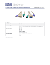
Features and Functions
1. Green LED- traffic indicator- illuminates when there is communication between the local and remote units.
2. Yellow LED- power indicator- illuminates when power has been supplied to the unit
3. Cat 5- RJ45 female- for connecting the CAT 5 cable
4. Video Connector- 15HD female- for connecting the local user's monitor
5. Mouse Connector- green female 6 miniDIN- for connecting the local user's mouse
6. Keyboard Connector- purple female 6 miniDIN- for connecting the local user's keyboard
7. Video Connector- blue 15HD male- for connecting to the video port on the CPU or KVM switch
8. Mouse Connector- green male 6 miniDIN- for connecting to the mouse port on the CPU or KVM switch
9. Keyboard Connector- purple male 6 miniDIN- for connecting to the keyboard port on the CPU or KVM switch
10. Keyboard Connector- purple female 6 miniDIN- for connecting the remote user's keyboard
11. Mouse Connector- green female 6 miniDIN- for connecting the remote user's mouse
12. 5VDC- 2.0A- connection jack for the TUV/CE approved AC adapter
13. Video Connector- 15HD female- for connecting the remote user's monitor
Features and Functions
7 8 9
1
3
S T - C 5 K V M - 6 0 0 L o c a l U n i t
2
4
5
6
F E A T U R E S A N D F U N C T I O N S
N T I
R
N e t w o r k T e c h n o l o g i e s I n c
X T E N D E X
-
+
N T I
R
N e t w o r k T e c h n o l o g i e s I n c
X T E N D E X
-
+
1 2
( F r o n t V i e w ) ( R e a r V i e w )
1 3
S T - C 5 K V M - 6 0 0 R e m o t e U n i t
1 11 0
1
3
2
1 2
-
+
N T I
R
N e t w o r k T e c h n o l o g i e s I n c
X T E N D E X
N T I
R
N e t w o r k T e c h n o l o g i e s I n c
X T E N D E X
-
+
( F r o n t V i e w ) ( R e a r V i e w )

3
Limitations
• Hot-plugging of devices is supported provided devices were originally connected at power-up.
• Devices connected to the Local and Remote Units must be identical. Same mice, same keyboards, etc.
• In order for two users to share a PS/2 CPU, the user in control must pause for at least 3 seconds before
another user can take control. After the 3 second pause, either user can take control of the CPU.
Preparation for Installation
• Locations should be chosen for the monitors, mice, and keyboards that also have space to connect the
Remote and Local Units within the distance provided by the cables. If extension cables are needed,
contact NTI for the cables required.
• The CAT5 cables must be run to the locations where the Remote and Local Units will be connected.
NOTE: If CAT5 cable is already installed in the wall and there are RJ45 wall outlets, it will be necessary to
obtain male-to-male straight through connection cables long enough to reach from the wall outlets to the
connection locations of the Remote and Local Units.
• A properly grounded, polarized, and preferably surge-protected 120V or 240V electrical outlet (depending
on the AC adapter being used) must be installed close enough to the connection location of the Remote
and Local Units, monitors, and CPU to plug them into.
• All cables should be installed in such a way that they do not cause stress on their connections to the
equipment. Extended lengths of cable hanging from a connection may interfere with the quality of that
connection. Secure cables as needed to minimize this.
• Properly shut down and disconnect the power from the CPU and monitors to be separated. If other
equipment is involved whose connections are being interrupted, be sure to refer to the instruction manuals
for that equipment for proper disconnection and re-connection procedures before proceeding.
Preparation for Installation
Limitations

4
Installation
The Local Unit
1. Plug the cables of the Local Unit into the back of the CPU. (See Fig. 1.)
a) Connect the purple 6 pin miniDIN cable end with the keyboard symbol
on it to the keyboard port on the back of the CPU.
b) Connect the green 6 pin miniDIN cable end with the mouse symbol
on it to the mouse port on the back of the CPU.
c) Connect the blue 15HD cable end to the VGA port on the back of the CPU.
Figure 1- Connect the Local Unit to the CPU
2. Make connections for a Local User (see Fig. 2)
a) Connect the cable from the local user's VGA monitor to the female 15HD port on the Local Unit.
b) Connect the local user's keyboard to the purple 6 pin miniDIN female port on the Local Unit.
c) Connect the local user's mouse to the green 6 pin miniDIN female port on the Local Unit.
Installation
(Mouse)
(Keyboard)
S T - C 5 K V M - 6 0 0 L o c a l U n i t
( F r o n t V i e w )
1 5 H D F e m a l e
V i d e o C o n n e c t o r
6 p i n m i n i D I N
M a l e C o n n e c t o r
( G R E E N - M O U S E )
( P U R P L E - K E Y B O A R D )
( B L U E - V I D E O )
P S / 2 C P U
6 p i n m i n i D I N
F e m a l e C o n n e c t o r
D E V I C E
C O N N E C T O R S
V I D E O
C O N N E C T O R
1 5 H D M a l e
V i d e o C o n n e c t o r
N T I
R
N e t w o r k T e c h n o l o g i e s I n c
X T E N D E X
-
+

5
Figure 2- Connect Local User Components to Local Unit
3. Connect the CAT5 cable to the “Cat 5” port on the Local Unit. (See Fig. 2.) When properly inserted
the cable end should snap into place.
Note: If an RJ45 wall outlet is being used, connect the other end of the extension cable to the
RJ45 wall outlet.
WARNING: Never connect the ST-C5KVM-600 Extender to an ethernet card, ethernet router,
hub or switch or other ethernet RJ45 connector of an ethernet device. Damage to devices connected
to the ethernet may result.
!
V G A
M u l t i - S c a n
M o n i t o r
P S / 2 K E Y B O A R D P S / 2 M O U S E
1 5 H D F e m a l e
V i d e o C o n n e c t o r
F r o n t V i e w o f
L o c a l U n i t
S T - C 5 K V M - 6 0 0 L o c a l U n i t ( F r o n t a n d R e a r V i e w )
C A T 5 C a b l e t o
R e m o t e U n i t
R e a r V i e w o f L o c a l U n i t
L o c a l U s e r ' s K e y b o a r d , M o n i t o r , a n d M o u s e
G r e e n T r a f f i c L E D
Y e l l o w P o w e r L E D
N T I
R
N e t w o r k T e c h n o l o g i e s I n c
X T E N D E X
-
+
6 p i n m i n i D I N
F e m a l e C o n n e c t o r

6
The Remote Unit
1. Position the Remote Unit such that the CAT5 cable, the monitor cable, device cables, and the AC
adapter power connector can each reach the Remote Unit comfortably.
2. Connect the monitor cable to the female 15HD video connector on the Remote Unit.
3. Connect the device(s) to the Remote Unit (see Fig. 3).
a. Connect the keyboard to the purple female 6 pin miniDIN connector on the Remote Unit.
b. Connect the mouse to the green female 6 pin miniDIN connector on the Remote Unit.
Figure 3- Connect the Extended Components to the Remote Unit
F r o n t V i e w o f
R e m o t e U n i t
S T - C 5 K V M - 6 0 0 R e m o t e U n i t ( F r o n t a n d R e a r V i e w )
R e a r V i e w o f R e m o t e U n i t
V G A
M u l t i - S c a n
M o n i t o r
P S / 2 K E Y B O A R D P S / 2 M O U S E
1 5 H D F e m a l e
V i d e o C o n n e c t o r
C A T 5 C a b l e t o
L o c a l U n i t
R e m o t e U s e r ' s K e y b o a r d , M o n i t o r , a n d M o u s e
6 p i n m i n i D I N
F e m a l e C o n n e c t o r
N T I
R
N e t w o r k T e c h n o l o g i e s I n c
X T E N D E X
-
+

7
4. Make sure the CAT5 cable has been installed in accordance with the “Preparation for Installation”
instructions on page 3. Connect the CAT5 cable to the “Cat 5” port on the Remote Unit. (See Fig. 3.)
When properly inserted the CAT5 cable end should snap into place.
Note: If an RJ45 wall outlet is being used, connect the other end of the extension cable to the RJ45
wall outlet.
WARNING: Never connect the ST-C5KVM-600 Extender to an ethernet card, ethernet router,
hub or switch or other ethernet RJ45 connector of an ethernet device. Damage to devices connected
to the ethernet may result.
Plug-in and Boot Up
1. Plug the power cord from the monitor into the power outlet.
2. Connect each AC adapter power connector to the 5VDC ports on the Remote and Local Units. Make sure
the power connectors go into each port all the way. Plug each AC adapter into a power outlet. The yellow
LED on the RJ45 connector of both the Remote and Local Units should illuminate, indicating that a proper
power connection has been made to them. (See Fig. 4.)
Figure 4- Connect the AC adapter to the Remote Unit
3. Turn ON the CPU and Monitor. They should each react as if they were directly connected to each other.
NOTE: The green LED on each RJ45 connector will illuminate anytime data traffic is passing between
the Local and Remote Units, indicating proper CAT5 cable connection and communication. (See Fig. 4)
Plu
g
-in and Boot Up
!
G r e e n T r a f f i c L E D
5 V D C
A d a p t e r
A D A P T E R
B a r r e l
( I n s i d e
b a r r e l )
( O u t s i d e
b a r r e l )
P o w e r C o n n e c t o r
2 . 1 m m x 5 . 5 m m F e m a l e
5 V D C @ 2 . 0 A O U T P U T
Y e l l o w P o w e r L E D
R e a r V i e w o f R e m o t e / L o c a l U n i t
5 V D C
2 A
-
+
C a t 5
M o n i t o r

8
Video Quality
Video quality adjustment is done automatically to assure the image is as clear as possible.
Note: When the cable is longer than 300 feet some colored lines can be seen at the black-to-white
transitions. This is a normal behavior and is caused by the different twisting rates of each pair of wires
in the CAT5 cable.
Technical Specifications
Maximum Resolution
(refresh frequency 60Hz)
1280 x 1024 - up to 600 feet
Video Compatibility SVGA, XGA, VGA
Video Quality Adjustment Automatic, for up to 600 feet of CAT5 cable
Video Coupling DC
Video Connectors HD15 male to CPU
HD15 female to monitor
Keyboard/Mouse Connectors Female 6 pin miniDIN to Keyboard and Mouse
Male 6 pin miniDIN to CPU device ports
Mouse and Keyboard Compatibility All PS/2 mice and keyboards
Local Keyboard and Mouse Current
Rating
500mA maximum
Remote Keyboard and Mouse Current
Rating
500mA maximum
Sync Types Supported Separate and composite TTL Level and sync on green
Interconnect Cable CAT 5/5e Solid STP EIA/TIA 568 B wiring w/ shielded male RJ45
connectors
Remote and Local Unit Power 120V or 240V at 50 or 60Hz-5VDC/2.0A via AC Adapters (2)
Dimensions 3.1" W x 3.4" D x 1" H
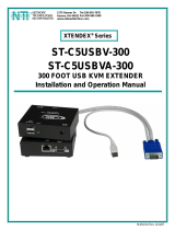
Interconnection Cable Wiring Method
The connection cable between the remote and local is terminated with RJ45 connectors and must be wired
according to the EIA/TIA 568 B industry standard. Wiring is as per the table and drawing below.
Pin Wire Color Pair Function
1 White/Orange 2 T
2Orange 2 R
3 White/Green 3 T
4Blue 1 R
5 White/Blue 1 T
6Green 3 R
7 White/Brown 4 T
8Brown 4 R
SH Drain wire - Shield
Figure 5- View looking into RJ45 female
T
1
+
R
2
-
T
3
+
R
4
-
T
5
+
R
6
-
T
7
+
R
8
-
Pair 2 Pair 1
Pair 4
Pair 3
V
ideo Qualit
y
Technical Specifications
Interconnection Cable Wirin
g
Method

9
Troubleshooting
Each and every piece of every product produced by Network Technologies Inc is 100% tested to exacting
specifications. We make every effort to insure trouble-free installation and operation of our products. If
problems are experienced while installing this product, please look over the troubleshooting chart below to see if
perhaps we can answer any questions that arise. If the answer is not found in the chart, please check the
FAQs (Frequently Asked Questions) at our website at http://www.nti1.com or contact us directly for help at 1-
800-742-8324 (800-RGB-TECH) in US & Canada or 1-330-562-7070 worldwide. We will be happy to assist in
any way we can.
Problem Cause Solution
Remote or Local Unit
yellow power LED does
not illuminate
• Power supply is not connected
or plugged-in.
• Make sure outlet is live and AC adapter is plugged-
in. (one for the Remote and one for the Local)
• Make sure 5VDC jack is fully connected
Local power LED does
not illuminate when the
CPU is powered
• The keyboard connector is not
properly plugged in
• Check keyboard connection
No Video on monitor
• One or more video cables is
loose or disconnected.
• No power to Remote or Local
Units.
• Video Cable was not attached
when CPU was booted.
• CAT5 cable is not connected.
• Check all video cable connections
• Make sure yellow LEDs are illuminated for local
and remote. If not, see solutions for first two
problems above.
• With all the cables properly connected, reboot the
CPU.
• Check cable connections. Make sure they are
snapped-in properly and completely and reboot.
Video Picture is not
sharp or is smeared
• All Video Cables are not firmly
seated.
• CAT5 cable is too long.
• The CAT5 cable is not
properly connected.
• Check all connections. Make sure all cables are
fully seated.
• Verify length is within specified limits-600'.
• Check cable connections. Make sure they are
snapped-in properly and completely.
The picture on the
monitor is black and
white, rather than color
The video cable was not attached
to the CPU when it was booted.
With the cables all properly connected, reboot the
CPU.
Monitor sometimes
loses sync, causing it
to go blank for a
second or two
• The CAT5 cable is not
properly connected.
• Check cable connections. Make sure they are
snapped-in properly and completely.
Wrong or missing
characters from those
typed
The keyboard may be in the wrong
mode.
• Disconnect keyboard at Remote Unit end and
reconnect.
• Reboot the system.
CPU doesn't detect the
keyboard and the
mouse
• Keyboard cable or mouse
cable are loose or reversed
• Cat 5 cable is too long
• Check cable connections
• Cat 5 cable can be no more than 600 feet in length
If the answer to a question is not in our troubleshooting chart or on our website and a call to us is required,
please have the following information available at the time of the call:
Troubleshootin
g

10
1. NTI Model Number and Serial Number (from the bottom) of the Local Unit and the Remote Unit.
Local M/N __________ S/N ______________
Remote M/N __________ S/N ______________
2. The total length of the CAT5 extension cable in use.______
3. Make and Model Numbers of the Monitor, Mouse, and Keyboard.
Monitor ___________________________________
Mouse ___________________________________
Keyboard __________________________________
4. Computer Information:
• Manufacturer ___________________ • BIOS Revision______________________________
• Model _________________________ • Operating System___________________________
• RAM __________________________ • Graphics Card Name and Model _______________
• BIOS Mfr._______________________ • Operating Video Resolution ___________________
5. Make and Model Number of any other equipment connected between the monitor and the CPU.
__________________________________________________________________________
ST-C5KVM-600 ST-C5KVM-600
REMOTE UNIT LOCAL UNIT
CE remark
This equipment has been tested and found to comply with the limits for Information Technology Equipment of
the European Community.
Manual 073-C Rev. 4/29/03
SERIAL NO:
DATE:
INSPECTED BY:
SERIAL NO:___________
DATE:________________
INSPECTED BY:____________
/