Page is loading ...

Step 1: Mount the 734
The back and ends of the 734 housing have wire entrances. The back also contains multiple mounting holes that allow
you to mount the module on a single‑gang switch box. DMP recommends mounting the 734 near the protected door.
1. Remove the PCB from the plastic housing by loosening the clips on
one side and gently lifting it out of the housing base.
2. Insert the included screws in the desired mounting hole locations
and tighten them to secure the housing to the surface.
3. Reinstall the PCB in the housing base.
734 Access Control Module
Quick Start Guide
Full Installation and Programming Guide
To view the full 734 Access Control Module Installation and Programming Guide, scan this QR code
or visit DMP.com.
This quick start guide walks you through installing the access control module.
RED
PROG
RED
KYPD OUT
DATA
XMT LED
WIEGAND
READ LED
RELAY
ON
NC
C
NO
GRN
YEL
RED + –
Piezo
1234 5 6 7 810 11 12 13 14
9
LC ASREDWHTGRN BLK Z1 Z2 Z3 Z4+ Z4–RA GND GND
KYPD IN
RED
ON
1 2 3 4
Reader
Inputs
Status
Indicator
Outputs Zones
To Panel
Keypad Bus
or AX-Bus
Piezo
Address DIP
Switches
Door Relay
Terminal
Indicator
LEDs
Keypad
Programming
Header
To Other
Keypad Bus
or AX-Bus
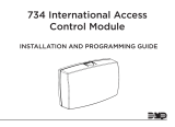
Step 2: Wire the Access Control Lock
The Form C relay draws up to 35 mA of current and contacts are rated for
10 Amps (resistive) at 12/24 VDC. When connecting multiple locks to the
Form C relay, the total current for all locks cannot exceed 10 Amps. The
three relay terminals marked NO C NC allow you to connect the device
wiring to the relay for module control. Use an additional power supply to
power magnetic locks and door strikes.
Model 333
Suppressor
–+
12/24 VDC
Power Supply
Normally Closed
Magnetic Door
Lock
Mag lock positive
to Terminal NC
Power supply positive
to Terminal C
Mag lock negative to
power supply negative
Figure 1: Typical Magnetic Lock Wiring
Model 333
Suppressor
–+
12/24 VDC
Power Supply
Normally Open
Door strike positive
to Terminal NO
Power supply positive
to Terminal C
Door strike negative to
power supply negative
DC Door Strike
Figure 2: Typical Door Strike Wiring
Step 3: Wire the 734
KYPD IN (Keypad In): Receives and transmits data to the panel Keypad bus/AX‑Bus.
KYPD OUT (Keypad Out): Receives and transmits data out to other keypad(s) or module(s). Install a dual‑connector
harness to allow connection to other devices up to the maximum number of devices supported.
Caution: When the 734 is powered from 24 VDC, do not connect devices to KYPD OUT header.

18205
INTRUSION • FIRE • ACCESS • NETWORKS
2500 North Partnership Boulevard
Springfield, Missouri 65803-8877
Domestic: 800.641.4282 | International: 417.831.9362
DMP.com
Designed, engineered, and
manufactured in Springfield, MO
using U.S. and global components.
LT-2612 22165
© 2022
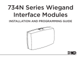
Step 5: Install the 333 Suppressor
Use the included 333 suppressor with the 734 to suppress any surges caused by
energizing a magnetic lock or door strike. Install the 333 across the module’s C
(common) and NO (normally open) or NC (normally closed) terminals.
If the device being controlled by the relay is connected to the NO and C terminals,
install the suppressor on the NO and C terminals. Conversely, if the device is connected
to the NC and C terminals, install the 333 Suppressor on NC and C terminals.
Step 6: Wire the Zone Terminals
Terminals 8 through 12 connect grounded zones 1 through 3. These zones have a grounded side and cannot be used for
fire‑initiating devices. Zones 2 and 3 can also be used for access control with zone 2 providing a bypass feature and zone
3 providing request to exit functionality. Terminals 13 and 14 connect to zone 4. Zone 4 provides a non‑powered Class B
ungrounded zone suitable for connection to fire devices such as heat detectors or pull stations.
Note: You must provide a mechanical means of resetting four‑wire smoke detectors or other latching devices on
zone4. The panel does not drop power to the Keypad Bus or AX‑Bus when a Sensor Reset is performed.
Use the supplied 311 1k Ohm End‑of‑Line (EOL) resistors on each zone. Refer to the panel programming guide for
programming instructions
Step 7: Connect a Card Reader
The 734 provides direct 12/24 VDC output to the reader on the RED terminal connection.
Wiegand Card Reader
The green wire carries Data Zero (D0), and the white wire carries Data One (D1). The red wire connects 12/24 VDC and
the black wire is ground.
OSDP Card Reader
For data transmission, connect the A (485 –) wire to the GRN terminal and the B (485 +) wire to the WHT terminal. For
reader power, connect the red (DC +) wire to the RED terminal and the black (DC –) wire to the BLK terminal.
Step 8: Set the 734 Address
To set the 734 address, move the DIP switches on the PCB to the appropriate positions. For complete address
instructions, scan the QR code at the beginning of the document.
Step 10: Program the Panel and 734
For all programming instructions, scan the QR code at the beginning of the document or refer to the appropriate panel
guide.
RED
PROG
PIEZO
RED KYPD IN RED KYPD OUT
RED
WIEGAND
READ LED
DATA
XMT LED
RELAY
ON
YEL GRN
734
Series
Module
Model 333
Suppressor
+–
NO CNC
Figure 3: 333 Suppressor
Installation on the 734
Step 4: Isolation Relay (Optional)
The Form C relay can control a device that draws less than 10 Amps of current. If a device draws more than 10 Amps of
current, or the sum of all devices controlled by the Form C relay exceeds 10 Amps, an isolation relay must be used.
Step 9: Connect the Power Supply
Power for the 734 can be provided by a 12 or 24 VDC power supply. The 12 VDC power can be provided by the panel
keypad bus or from a separate power supply. The 24 VDC power supply can be connected directly to the relay terminal
block (J1).
Warning: To avoid the risk of equipment damage, do not exceed 750 mA total output current for zones connected
to the module.
/