Page is loading ...

Installation Instructions
Original Instructions
Hiperface-to-DSL Feedback Converter Kit
Catalog Number 2198-H2DCK
Summary of Changes
Added EAC logo to back cover.
About the Feedback Converter Kit
This kit is designed for use with Allen-Bradley® 2090-Series motor feedback cables and provides
wire terminations for 10 Hiperface encoder signals. The Hiperface encoder signals are converted
into compatible digital-servo-link (DSL) feedback signals. You must wire the 10-pin converter
kit connector and assemble the connector housing with the cable shield and cable jacket properly
positioned.
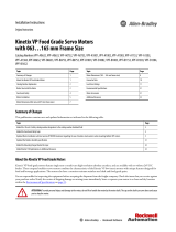
Prepare the Cables
To prepare your existing Bulletin 2090 cables for use with the feedback converter kit, some
preparation is necessary so that the cable shield, conductor lengths, and strip lengths are correct.
Make sure your feedback cable preparation follows these guidelines:
• Trim the shield flush so that no strands can cause a short to adjacent terminals.
• Measure the conductor lengths so they are long enough to provide a service loop.
• Remove just enough insulation from each conductor to provide the proper strip length.
Feedback Cable
12.0 (0.5)
5.0 (0.2)
115 (4.5)
103 (4.0)
Cable Jacket
Cable Shield
Shield Clamp
Cable Positioned Where Cover

2 Rockwell Automation Publication 2198-IN006D-EN-P - October 2019
Hiperface-to-DSL Feedback Converter Kit
Install the Converter Kit
Follow these steps to install the converter kit.
1. Remove the cover and route signal wires to the proper terminals leaving service loops for
each connection.
See Connector Data
on page 3 for the 10-pin terminal pinout.
2. Tighten terminal screws to achieve 0.25 N•m (2.2 lb•in), maximum torque.
3. Apply the shield clamp to the 12 mm (0.5 in.) of exposed cable shield to achieve a high-
frequency bond between the shield braid and clamp.
4. Attach the tie wrap (supplied with the kit) for stress relief.
5. Tighten clamp screws to achieve 0.3 N•m (2.6 lb•in) maximum torque.
6. Replace the cover and install cover screws.
Tighten cover screws to achieve 0.3 N•m (2.6 lb•in) maximum torque.
7. Insert the two-pin DSL connector into the drive connector and attach the mounting
bracket in one of three mounting positions.
– Mounting position depends on the drive family.
– Mounting-hole protective cover on the drive depends on the drive family.
See Additional Resources
on page 4 for access to the user manual for your servo drive.
8. Tighten mounting screws to achieve 0.4 N•m (3.5 lb•in) maximum torque.
IMPORTANT The purpose of the shield clamp is to provide a proper ground and improve system
performance. To achieve this, clamping the exposed braid under the shield clamp is
critical.
14
11
10
7
6
5
4
3
2
1
Clamp Screws (2)
Service Loops
Tie Wrap for Stress Relief
and Wire Management
Mounting Screws (2)
Mounting Bracket in
Top Mounting Position
Middle Mounting Position
Bottom Mounting Position
Attach the mounting bracket in
the mounting position specified
for your Kinetix® drive.
10-pin
Connector
2-pin DSL
Connector
Shield Clamp
1. Place exposed cable shield
in the channel.
2. Place the shield clamp over
the exposed shield.
3. Tighten screws, torque
0.3 N•m (2.6 lb•in).
Exposed Shield Aligned
in the Cable Channel

Rockwell Automation Publication 2198-IN006D-EN-P - October 2019 3
Hiperface-to-DSL Feedback Converter Kit
Connector Data
Converter Kit Specifications
Attribute Value
Cable diameter 6.5…11.9 mm (0.26…0.47 in.)
Screw terminal wire size 0.08…1.5 mm
2
(28…16 AWG)
Recommended feedback wire strip length 5 mm (0.2 in.) single conductor
Recommended torque
Mounting screws
Terminal screws
Clamp and cover screws
0.4 N•m (3.5 lb•in)
0.22…0.25 N•m (1.9…2.2 lb•in)
0.3 N•m (2.6 lb•in)
Kit contents
• Converter kit, mounting and cover screws
•Shield clamp, screws
• Mounting bracket, captive screws
• Clamp spacer (Kinetix 5500 drives)
•Tie wrap
• Spare screws (2)
14
11
10
7
6
5
4
3
2
1
Converter Kit Pinout
Pin
Signal
Wire Color
1SIN+ Black
2SIN–White/Black
3COS+Red
4COS–White/Red
5DATA+ Green
6ECOM
(1)
(1) The ECOM and TS- connections are tied together and connect to
the cable shield.
White/Gray
7EPWR_9V
(2)
(2) The converter kit generates 5V and 9V from a 12V supply coming
from the drive. The 5V supply is used by 5V encoders. The 9V
supply is used by 9V encoders.
Orange
10 DATA– White/Green
11 TS White/Orange
14 EPWR_5V
(2)
Gray

Allen-Bradley, Kinetix, Rockwell Automation, and Rockwell Software are trademarks of Rockwell Automation, Inc.
Trademarks not belonging to Rockwell Automation are property of their respective companies.
Rockwell Otomasyon Ticaret A.Ş., Kar Plaza İş Merkezi E Blok Kat:6 34752 İçerenköy, İstanbul, Tel: +90 (216) 5698400
Rockwell Automation maintains current product environmental information on its website at
http://www.rockwellautomation.com/rockwellautomation/about-us/sustainability-ethics/product-environmental-compliance.page
.
Publication 2198-IN006D-EN-P - October 2019 8016732
Supersedes Publication 2198-IN006C-EN-P - May 2017 Copyright © 2019 Rockwell Automation, Inc. All rights reserved. Printed in the U.S.A.
At the end of its life, this equipment should be collected separately from any unsorted municipal
waste.
Clamp Spacer Installation
A clamp spacer is included with the 2198-H2DCK feedback converter kit for power cable
diameters that are too small for a tight fit within the Kinetix 5500 drive clamp alone.
Additional Resources
You can view or download publications at http://www.rockwellautomation.com/literature.
IMPORTANT In addition to this publication, we strongly recommend that you refer to your drive user
manual for additional information about making feedback connections to the drive.
Resource Description
Kinetix 5700 Servo Drives User Manual, publication 2198-UM002 Provides information to install, configure, start, and
troubleshoot your Kinetix servo drive system. Also includes
drive-specific installation and grounding techniques for the
2198-H2DCK feedback converter kit.
Kinetix 5500 Servo Drives User Manual, publication 2198-UM001
Insert the clamp spacer when
the cable diameter is smaller
than the drive clamp alone.
Kinetix 5500 Servo Drive
(front views)
Clamp Spacer (if needed)
Shield Clamp
Clamp Screws
2.0 N•m (17.7 lb•in.)
Clamp Spacer Added
for Small Diameter Cable
Retention Screw
(remove only to insert
the clamp spacer)
Kinetix 5500 Servo Drive
(side view)
Retention Screw
/