Allen-Bradley MPL-A310, MPL-A320, MPL-A330, MPL-A420, MPL-A430, MPL-A4530, MPL-A4540, MPL-A4560, MPL-A520, MPL-A540, MPL-A560, MPL-B310, MPL-B Installation Instructions Manual
- Type
- Installation Instructions Manual

Installation Instructions
Original Instructions
MP-Series Low-inertia Servo Motor
with 100 mm to 165 mm Frame Size
Catalog Numbers MPL-A310, MPL-A320, MPL-A330, MPL-A420, MPL-A430, MPL-A4530,
MPL-A4540, MPL-A4560, MPL-A520, MPL-A540, MPL-A560, MPL-B310, MPL-B320,
MPL-B330, MPL-B420, MPL-B430, MPL-B4530, MPL-B4540, MPL-B4560, MPL-B520,
MPL-B540, MPL-B560, MPL-B580
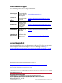
Summary of Changes
This manual contains new and updated information as indicated in the following table.
Topic Page
Catalog Number Explanation 2
About the MP-Series Low-inertia Motors 3
Before You Begin 3
Install the Motor 8
Motor with ATEX Rating Installations 12
Product Dimensions 13
Motor Load Force Ratings 17
Connector Data 19
Remove and Install a Shaft Key 21
Motor Cables and Accessory Kits 22
Specifications 23
Additional Resources 24
Topic Page
Corrected designation of motor bolt circle and hole diameters. 13, 15
Clarified column headings for encoder types. 20

2 Rockwell Automation Publication MP-IN001J-EN-P - June 2018
MP-Series Low-inertia Servo Motor with 100 mm to 165 mm Frame Size
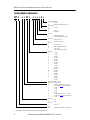
Catalog Number Explanation
MP L -
x
x
10
x
-
x
x
x
x
A
x
Factory Designated Options
A=Standard
H = ATEX protection rating of Group II, Zone 2
Mounting Flange
A=IEC metric
Brake
2=No brake
4=24V DC brake
Connectors
2 = Circular bayonet, facing shaft
7 = Circular DIN, right angle, 180° rotatable
Shaft Key/Seal
J = Shaft key/no shaft seal
K = No shaft key/no shaft seal
Feedback
H=
2000 line encoder
(1)
(1) Not available on catalog number MPL-x5xxx or larger (>165 mm frame sizes).
M = Multi-turn high-resolution encoder
R=
2-pole resolver
(1)
S = Single-turn high-resolution encoder
Rated Speed
A = 500 rpm
B = 1000 rpm
C = 1500 rpm
D = 2000 rpm
E = 2500 rpm
F = 3000 rpm
G = 3250 rpm
H = 3500 rpm
J = 3750 rpm
K = 4000 rpm
L = 4250 rpm
M = 4500 rpm
N = 4750 rpm
P = 5000 rpm
Q = 5250 rpm
R = 5500 rpm
S = 5750 rpm
T = 6000 rpm
Magnetic Stack Length (10 = 1.0 in.)
Frame Size (IEC 72-1 flange number)
15 = 63 mm small frame motors (63…75 mm)
2 = 75 mm refer to page 24
for this product manual
3 = 100 mm
4 = 115 mm
45 = 130 mm
5 = 165 mm
6 = 215 mm large frame motors (215…300 mm)
8 = 265 mm refer to page 24
for this product manual
9 = 300 mm
Voltage Class
A = 200V
B = 400V
Series Type
L = Low inertia
Series
MP = Premium permanent-magnet rotary servo motor

Rockwell Automation Publication MP-IN001J-EN-P - June 2018 3
MP-Series Low-inertia Servo Motor with 100 mm to 165 mm Frame Size
About the MP-Series Low-inertia Motors
MP-Series™ low-inertia (Bulletin MPL) motors feature single-turn or multi-turn high-resolution
encoders, and are available with 24V DC brakes. These compact brushless servo motors meet the
demanding requirements of high-performance motion systems.
Before You Begin
Remove all packing material from within and around the item. After unpacking, verify the
nameplate catalog number against the purchase order.
1. Remove the motor carefully from its shipping container.
2. Visually inspect the motor for any damage.
3. Examine the motor frame, front output shaft, and mounting pilot for any anomalies.
4. Notify the carrier of any shipping damage immediately.
Keep the original packing material in case you must return the product for repair or transport it
to another location. Use both the inner and outer packing cartons to provide adequate
protection for a unit that is returned for service.
Store or operate your motor in a clean and dry location within the environmental conditions that
are listed in Specifications
on page 23.
Removing the Shaft Cap
Use your hand to remove the protective cap that is installed on the motor shaft or pry off the cap
with a screwdriver. Do not use a hammer or other tools as they can damage the motor shaft.
ATTENTION: To avoid personal injury and damage to the motor, do not lift or handle the motor
by the motor shaft. The cap on the shaft can come loose and cause you to drop the motor.
ATTENTION: Do not attempt to open and modify the motor beyond changing the connector
orientation as described in Change the Orientation of the Connectors
on page 8.
Only an authorized Allen-Bradley repair center can service this item. See Rockwell Automation
Support for assistance to locate the nearest repair center.

4 Rockwell Automation Publication MP-IN001J-EN-P - June 2018
MP-Series Low-inertia Servo Motor with 100 mm to 165 mm Frame Size
Prolonging Motor Life
Proper design and maintenance can increase the life of a servo motor. Follow these guidelines to
maximize the life of a servo motor within your environment:
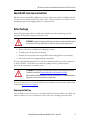
• Always provide a drip loop in each cable to carry liquids away from the connection to the
motor.
• If possible, provide shields that helps protect the motor housing, shaft seals, and their
junctions from contamination by foreign matter or fluids.
• Shaft seals are subject to wear and require periodic inspection and replacement.
Replacement is recommended every 3 months, not to exceed 12 months, depending on
use. See Shaft Seal Kits on page 22 for more information on shaft seals.
• Inspect the motor and seals for damage or wear regularly. If damage or excessive wear is
observed, replace the item.
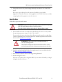
• The brake option on this servo motor is a spring-set holding brake that releases when
voltage is applied to the brake coil. A separate power source is required to disengage the
brake. This power source is applied by a servo motor controller or manual operator
control.
If system main power fails, holding brakes can withstand occasional use as stopping
brakes. However, this creates rotational mechanical backlash that can damage the system,
increase brake wear, and reduce brake life.
IMPORTANT Holding brakes are not designed to stop rotation of the motor shaft, and they are not
intended to be used as a safety device. They are designed to hold a motor shaft at 0 rpm for
up to the rated brake holding torque.
Follow these steps to prevent motor shaft rotation.
1.Command the servo drive to 0 rpm.
2.Verify the motor is at 0 rpm.
3.Engage the brake.
4.Disable the drive.
Disabling the drive removes the potential for brake wear caused by a badly-tuned servo
system oscillating the shaft.
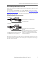
The cable enters beneath the
motor and forms a drip loop.
The cable enters above the
motor and does not form a
drip loop.

Rockwell Automation Publication MP-IN001J-EN-P - June 2018 5
MP-Series Low-inertia Servo Motor with 100 mm to 165 mm Frame Size
Using Shaft Seals
An additional seal is required on the motor shaft near the motor front bearing if the shaft is
exposed to fluids or significant amounts of fine dust. This includes lubricating oil from a
gearbox. An IP66 rating for the motor requires the use of a shaft seal and environmentally sealed
connectors/cables. The additional seal is not recommended in applications where the motor
shaft area is free of liquids or fine dust, and a lower rating is sufficient:
•SeeSpecifications
on page 23 for a brief description of the IP rating for these MP-Series
motors.
•SeeShaft Seal Kits on page 22 to find the catalog numbers of seal kits available for your
motor.
• See Kinetix® Motion Accessories Specifications, publication KNX-TD004
, to find
environmentally sealed connectors and cables compatible with the MP-Series motors.
Using Couplings and Pulleys
Mechanical connections to the motor shaft, such as couplings and pulleys, require a torsionally
rigid coupling or a reinforced timing belt. The high dynamic performance of servo motors can
cause couplings, pulleys, or belts to loosen or slip over time. A loose or slipping connection can
cause system instability and damage the motor shaft. All connections between the system and the
servo motor shaft must be rigid to achieve acceptable response from the system. Periodically
inspect connections to verify their rigidity.
When mounting couplings or pulleys to the motor shaft, be sure that the connections are
properly aligned and that axial and radial loads are within the specifications of the motor.
See Motor Load Force Ratings
on page 17 for guidelines to achieve 20,000 hours of motor
bearing life.
ATTENTION: Damage can occur to the motor bearings and the feedback device if sharp impact
to the shaft is applied during installation of couplings and pulleys. Damage to the feedback
device can result by applying leverage from the motor mounting face to remove devices
mounted on the motor shaft.
Do not strike the shaft, couplings, or pulleys with tools during installation or removal. Use a
wheel puller to apply pressure from the user end of the shaft and remove any friction-fit or
stuck device from the motor shaft.

6 Rockwell Automation Publication MP-IN001J-EN-P - June 2018
MP-Series Low-inertia Servo Motor with 100 mm to 165 mm Frame Size
Preventing Electrical Noise
Electromagnetic interference (EMI), commonly called noise, can cause poor motor performance
by inducing stray signals.
Follow these guidelines to prevent the effects of EMI:
• Isolate the power transformers, or install line filters on all AC input power lines.
• Separate signal cables from motor cabling and power wiring. Do not route signal cables
with motor and power wires, or over the vent openings of servo drives.
• Ground all equipment by using a single-point parallel ground system that employs
ground bus bars or large straps. If necessary, use additional electrical noise reduction
techniques to reduce EMI in noisy environments.
See System Design for Control of Electrical Noise Reference Manual, publication
GMC-RM001
, for additional information on reducing the effects of EMI by improving the
system level electromagnetic compatibility (EMC).
Build and Install the Cables
Correct cable routing and careful cable construction improve system electromagnetic
compatibility (EMC).
Follow these guidelines to build and install the cables:
• Keep the wire lengths as short as possible.
• Route noise sensitive wiring (encoder, serial, and I/O) away from input power and motor
power wiring.
• Separate cables by 0.3 m (1 ft) minimum for every 9 m (30 ft) of parallel run.
• Ground both ends of the encoder cable shield and twist the signal wire pairs to help
prevent EMI from other equipment.
ATTENTION: High voltage can be present on the shield of a power cable, if the shield is not
grounded.
Verify that there is a connection to ground for any power cable shield.
ATTENTION: MP-Series motors produce leakage current in the protective earthing conductor
that exceeds 3.5 mA AC and/or 10 mA DC.
Be sure to properly ground the motor cables per the drive installation instructions.

Rockwell Automation Publication MP-IN001J-EN-P - June 2018 7
MP-Series Low-inertia Servo Motor with 100 mm to 165 mm Frame Size
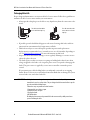
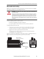
Ground Shielded Signal Wires Within a Power Cable
Always connect the shield on any signal wire pair that is routed inside a power cable to the overall
machine ground.
If you are installing a 2090-XXNPMF-xxSxx or 2090-CPBM4DF-xxAFxx power with brake
cable, loop the signal wire pairs to the overall cable shield as shown in Grounding of Signal Wire
Shields in a Power Cable on page 7. Then clamp all shields together in the power cable (chassis)
ground connection on the drive.
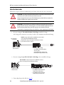
Grounding of Signal Wire Shields in a Power Cable
The signal wire pairs within a power cable often carry a 24V DC brake signal, but can also carry
logic signals. Grounding the shield that surrounds the signal wires dissipates an induced voltage
and reduces the effects of EMI.
Shielded Signal Wires (two pairs) within Power Cable
Overall Power Cable Shield
Signal Wire Shield (one of two) Contacts Overall Power
Cable Shield
Factory Supplied
Field Modified
All power and signal wire shields must connect to machine ground.
The diagram shows one of the two signal wires in the correct
position. Connect both signal wire shields and the overall power
cable shield to machine ground.
2090-XXNPMF-xxSxx (shown) contains two signal wire pairs.
2090-CPBM4DF-xxAFxx contains one signal wire pair.

8 Rockwell Automation Publication MP-IN001J-EN-P - June 2018
MP-Series Low-inertia Servo Motor with 100 mm to 165 mm Frame Size
Install the Motor
MP-Series motors include a mounting pilot for aligning the motor on the machine. Preferred
fasteners are stainless steel. The installation must comply with all local regulations and use
equipment and installation practices that promote safety and electromagnetic compatibility.
Change the Orientation of the Connectors
MP-Series motors use two styles of connectors. The connector style is identified by a 2 or a 7 as
the connector variable in the motor catalog number. For example, MPx-xxxxx-xx2xxx or
MPx-xxxxx-xx7xxx:
• A 2 indicates a circular bayonet connector, facing the shaft.
• A 7 indicates a circular DIN, right angle, rotatable connector.
Rotatable Circular DIN Connector (catalog number MPL-xxxxx-xx7xxx)
The circular DIN connector housing can be rotated up to 180° in either direction.
Follow these steps to turn the DIN connectors.
1. Mount and fully seat a mating cable on the connector.
ATTENTION: Unmounted motors, disconnected mechanical couplings, loose shaft keys, and
disconnected cables are dangerous if power is applied.
Lock-out and tag-out disassembled equipment (restrict electrical power).
Before applying power to the motor, remove the shaft key and other mechanical couplings that
can be thrown from the shaft.
ATTENTION: Make sure that cables are installed and restrained to help prevent uneven tension
or flexing at the cable connections.
Excessive and uneven lateral force on the cable can inhibit environmental sealing as the cable
flexes.
ATTENTION: Connectors are designed to be rotated into a fixed position during motor
installation, and remain in that position without further adjustment. Do not rotate the
connector multiple times, and do not use tools or excessive force to rotate the connector.
Excessive rotation or force can damage the connector seal and reduce the international
protection (IP) rating of the motor as outlined in Specifications
on page 23.

Rockwell Automation Publication MP-IN001J-EN-P - June 2018 9
MP-Series Low-inertia Servo Motor with 100 mm to 165 mm Frame Size
2. Grasp both connectors by their housings and slowly rotate them to the outside of the
motor.
If necessary, repeat this step for each connector (feedback or power/brake).
Apply force to only the connectors; do not apply force to the cable. Do not use tools (for
example, pliers and vise-grips) to rotate the connector.
Mount the Motor
Follow these steps to mount the motor.
1. Provide sufficient clearance, heatsink mass, and airflow for the motor so it stays within
the operating temperature range of 0…40 °C (32…104 °F).
Do not enclose the motor unless forced air is blown across the motor for cooling. Keep
other heat producing devices away from the motor. Heatsink requirements are listed in a
footnote to the Specifications
on page 23.
2. Verify the axial and radial shaft loads of your application do not exceed those listed in
the Motor Load Force Ratings
on page 17.
3. Place the motor with the connector housing pointing downward.
4. Mount and align the motor.
Electronic zero (index pulse or Stegmann ABS = 0) occurs when the shaft key or dimple
is aligned with the connectors.
ATTENTION: Damage can occur to the motor bearings and the feedback device if sharp impact
to the shaft is applied during installation of couplings and pulleys.
Do not strike the shaft, couplings, or pulleys with tools during installation or removal.
ATTENTION: Outer surfaces of the motor can reach high temperatures of
125 °C (257 °F) during operation.
Take precautions to help prevent accidental contact with hot surfaces. Consider
motor surface temperature when selecting motor mating connections and cables.

10 Rockwell Automation Publication MP-IN001J-EN-P - June 2018
MP-Series Low-inertia Servo Motor with 100 mm to 165 mm Frame Size
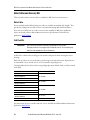
Attach the Motor Cables
Follow these steps to attach the feedback and power/brake cables after the motor is mounted.
1. If you are using the Threaded DIN (M4) Cable Plugs, install the O-rings.
An O-ring on the connector is necessary to achieve the maximum environmental rating.
2. If you are using the SpeedTec DIN (M7) Cable Plugs, do not install the O-rings.
3. Form a drip loop in the cable (see page 4
).
ATTENTION: Servo drive power must be turned off before connecting or disconnecting the cables
to the motor, and if a cable is left disconnected at the motor end.
Arcing or unexpected motion can occur if the feedback, power, or brake cables are connected or
disconnected while power is applied to the servo drive.
ATTENTION: Be sure that cables are installed and restrained to help prevent uneven tension or
flexing at the cable connectors. Provide support at 3 m (10 ft) intervals throughout the cable run.
Excessive and uneven lateral force at the cable connectors can result in the connector’s
environmental seal opening and closing as the cable flexes, or wires separating at the cable gland.
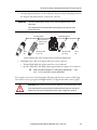
SpeedTec-ready DIN
Motor Connector
Threaded DIN (M4) Cable Plug
• 2090-XXNxMF-Sxx standard feedback
and power cables
• 2090-CxxM4DF-xxAFxx continuous-flex
feedback, power, and power/brake cables
Install the O-ring on the SpeedTec-ready DIN motor connector when
you are using the threaded DIN (M4) cable plugs.
Verify that the O-ring is not damaged, not twisted, and rests in the
groove near the rear of the connector.
Groove Reserved
for Cable Plug
Do not install the O-ring on the SpeedTec-ready DIN motor connector
when you are using the SpeedTec DIN (M7) cable plugs.
SpeedTec DIN (M7) Cable Plug
• 2090-CFBM7Dx-xxAxxx standard and
continuous-flex feedback cables
• 2090-CPxM7DF-xxAxxx standard and
continuous-flex power/brake cables
SpeedTec-ready DIN
Motor Connectors

Rockwell Automation Publication MP-IN001J-EN-P - June 2018 11
MP-Series Low-inertia Servo Motor with 100 mm to 165 mm Frame Size
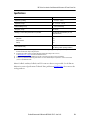
4. Carefully align the flat surface on the feedback or the power/brake cable plug (shown in
the diagram) with the flat surface on the motor connector.
5. Hand tighten the collar on the plug to fully seat it on the connector:
• Threaded DIN (M4) cable plugs require five to six revolutions.
• SpeedTec DIN (M7) cable plugs require approximately one-quarter of a revolution.
Do not apply excessive force when mating the cable plug with the motor connector. If the plug
and connector do not go together with light hand force, realign the flat surfaces and try again.
IMPORTANT The motor orientation that is shown is used to show the alignment marker on each
cable socket.
The recommended motor orientation when installed positions the connectors at the
bottom of the motor.
TIP A fully-seated threaded plug leaves a small opening, approximately 1…4 mm
(0.04…0.16 in.), between the connector and the plug.
ATTENTION: Align the keyed connectors and hand-tighten the recommended number of turns.
If you cannot tighten the connectors by hand, verify that the keyed connectors are properly
aligned. Do not use tools (for example, pliers and vise-grips) to tighten the connectors.
Flat Surface with
Logo on Top
Feedback Plug Options
Tab on
Side
Power Plug Options
Top of connector is
relative to motor
orientation.
Flat Surface with
Logo on Top
Tab on
Top
Connector plugs have either a tab or a flat surface with a logo to indicate the alignment point.

12 Rockwell Automation Publication MP-IN001J-EN-P - June 2018
MP-Series Low-inertia Servo Motor with 100 mm to 165 mm Frame Size
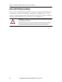
Motor with ATEX Rating Installations
If your motor has an ATEX rating for hazardous environments, complete the following step. The
catalog number on ATEX motor nameplates ends with H, for example MPL-xxxx-xxxxxH.
Verify the continuity and functionality of the thermal switch signals, TS+ and TS-, transmitted
through the feedback cable that connects the motor to its controlling drive.
ATTENTION: It is mandatory that the motion system monitor the thermal switch signals from
a motor requiring an ATEX rating.
The intrinsic safety protection concepts in the ATEX Direction 94/9/EC must be enabled by
connecting the thermal switch signals from the motor to the motion control system.

Rockwell Automation Publication MP-IN001J-EN-P - June 2018 13
MP-Series Low-inertia Servo Motor with 100 mm to 165 mm Frame Size
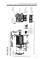
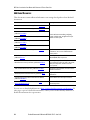
Product Dimensions
This section provides dimensions for the motors.
Dimensions for Bayonet Connectors (catalog number MPL-xxxxx-xx2xxx)
L
P
GE
LA
LB
T
L-LB
LE
AD
HD
N
F
D
S (diameter of holes)
M (diameter of bolt circle)
Shaft End Hole
Thread and Depth
(Pilot Diameter)
Feedback and Power
Connectors
(1)
(left to right)
67.8 (2.67)
Feedback, Power, and Brake
Connectors
(1)
(left to right)
88.9 (3.5)
Shaft Key
MPL-x3xx = 5 x 5 x 25
MPL-x4xx = 6 x 6 x 25
MPL-x45xx = 8 x 7 x 32
MPL-x520, x540, x560 = 8 x 7 x 40
MPL-x580 = 10 x 8 x 59
MPL-xxxxx-xx2xxx
Connector
Add for High-
Resolution End Cap
3.3 (0.13)
(1)Electronic zero (index pulse or Stegmann ABS = 0) occurs when the shaft key or dimple (not shown) is aligned with the connectors (as shown).

14 Rockwell Automation Publication MP-IN001J-EN-P - June 2018
MP-Series Low-inertia Servo Motor with 100 mm to 165 mm Frame Size
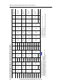
Dimensions for Bayonet Connectors (catalog number MPL-xxxxx-xx2xxx)
Motor Cat. No.
AD
mm (in.)
D
(1)
mm (in.)
HD
mm (in.)
L
(2), (3)
mm (in.)
L-LB
(4)
mm (in.)
LA
mm (in.)
LB
(2),(3)
mm (in.)
LD
(2)
mm (in.)
M
mm (in.)
N
(1)
mm (in.)
P
mm (in.)
S
(5)
mm (in.)
T
mm (in.)
F
(6)
mm (in.)
GE
(7)
mm (in.)
End of Shaft
Thread and Depth
of Hole
MPL-A/B310
80.9
(3.19)
16.0
(0.629)
125.7
(4.95)
164.7
(6.49)
40.0
(1.58)
9.9
(0.39)
124.7
(4.91)
70.7
(2.78)
100.0
(3.937)
80.0
(3.15)
89.4
(3.52)
7.0
(0.283)
2.87
(0.113)
5.0
(0.20)
3.0
(0.12)
M5 x 0.8-6H
12.5 (0.49)
MPL-A/B320
190.1
(7.49)
150.1
(5.91)
96.1
(3.78)
MPL-A/B330
215.5
(8.49)
175.5
(6.91)
121.5
(4.78)
MPL-A/B420
83.9
(3.3)
19.0
(0.748)
132.8
(5.23)
186.5
(7.35)
40.0
(1.575)
10.2
(0.40)
146.5
(5.77)
92.5
(3.64)
115.0
(4.528)
95.0
(3.74)
98.3
(3.87)
10.0
(0.401)
2.87
(0.113)
6.0
(0.24)
3.5
(0.138)
M6 x 1.0-6H
16 (0.63)
MPL-A/B430
211.9
(8.345)
171.9
(6.77)
117.9
(4.64)
MPL-A/B4530
91.5
(3.6)
24.0
(0.945)
148.3
(5.84)
225.2
(8.87)
50.0
(1.97)
12.2
(0.48)
175.2
(6.90)
121.2
(4.77)
130.0
(5.118)
110.0
(4.331)
113.7
(4.48)
10.0
(0.401)
3.38
(0.133)
8.0
(0.31)
4.0
(0.158)
M8 x 1.25 -6H
19 (0.75)
MPL-A/B4540
250.6
(9.87)
200.6
(7.90)
146.6
(5.77)
MPL-A/B4560
304.7
(11.99)
254.7
(10.03)
197.4
(7.77)
MPL-A/B520
106.2
(4.18)
28.0
(1.1)
178.1
(7.01)
233.7
(9.20)
60.0
(2.38)
13.97
(0.55)
173.7
(6.84)
115.8
(4.56)
165.0
(6.496)
130.0
(5.118)
143.5
(5.65)
12.0
(0.481)
3.38
(0.133)
8.0
(0.31)
4.0
(0.158)
M10 x 1.5-6H
22 (0.87)
MPL-A/B540
284.5
(11.20)
224.5
(8.84)
166.9
(6.57)
MPL-A/B560
335.3
(13.20)
275.3
(10.84)
217.7
(8.56)
MPL-B580
(8)
32.0
(1.26)
406.1
(15.99)
80.0
(3.15)
326.1
(12.84)
268.5
(10.57)
10.0
(0.39)
5.0
(0.197)
M12 x 1.75-6H
28 (1.10)
(1) Refer to Kinetix Rotary Motion Specifications Technical Data, publication KNX-TD001
, for tolerances on these measurements.
(2) Motors with brake, add this value to the dimension:
MPL-x310 through -x330: add 34.5 mm (1.36 in.) to L, LB, and LD.
MPL-x420 through -x4560: add 48.5 mm (1.91 in.) to L, LB, and LD.
MPL-x520 through -x580 add 51.6 mm (2.03 in.) to L and LB, and 45.6 mm (1.79 in.) to LD.
(3) Motors with high-resolution feedback, add 3.3 mm (0.13 in.) to L and LB.
(4) Tolerance is ±0.7 (±0.028).
(5) x3xx and x4xx tolerance is +0.36 (±0.0007), x5xx is +0.43 (±0.008).
(6) Tolerance is -0.03 (-0.001).
(7) Tolerance is +0.1 (+0.004).
(8) This motor is available only with 460V windings (catalog number MPL-B580).

Rockwell Automation Publication MP-IN001J-EN-P - June 2018 15
MP-Series Low-inertia Servo Motor with 100 mm to 165 mm Frame Size
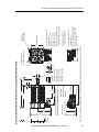
Dimensions for Rotatable Circular DIN Connectors (catalog number MPL-xxxxx-xx7xxx)
AD
HD
L
P
GE
LA
LB
T
L-LB
D
LE
N
LD
F
S (diameter of holes)
M (diameter of bolt circle)
Shaft End Hole
Thread and Depth
(Pilot Diameter)
(1)Electronic zero (index pulse or Stegmann ABS = 0) occurs when the shaft key or dimple (not shown) is aligned with the connectors (as shown).
M23 Power/Brake Connector
(1)
is standard on the
MPL-x3xx = 66.1 (2.60)
MPL-x4xx = 67.7 (2.66)
MPL-x45xx = 67.7 (2.66)
MPL-B520-xx7xxx, MPL-B540-xx7xxx,
and MPL-B560-xx7xxx = 68.2 (2.68)
Shaft Key
MPL-x3xx = 5 x 5 x 25
MPL-x4xx = 6 x 6 x 25
MPL-x45xx = 8 x 7 x 32
MPL-x5xx = 8 x 7 x 40
MPL-x580 = 10 x 8 x 59
M23 Feedback Connector
(1)
is standard on all MPL motors
M40 Power/Brake Connector
(1)
is standard on the
MPL-A520-xx7xxx, MPL-A540-xx7xxx,
MPL-A560-xx7xxx, and MPL-B580x-
xx7xxx = 71.2 (2.80)
MPL-x5xx
End Cap
Dimensions for M40 Power/Brake Connector on the
MPL-A5xxx-xx7xxx and the MPL-B580x-xx7xxx motors.
M23 Feedback
Connector shown for
comparison
HD + 22.95 (9.01)
AD + 22.99 (0.90)
LE - 31 (1.22)
LD + 2.0 (0.07)

16 Rockwell Automation Publication MP-IN001J-EN-P - June 2018
MP-Series Low-inertia Servo Motor with 100 mm to 165 mm Frame Size
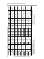
Dimensions for Rotatable Circular DIN Connectors (catalog number MPL-xxxxx-xx7xxx)
Motor Cat. No.
AD
mm (in.)
D
(1)
mm (in.)
HD
mm (in.)
L
(2)
mm (in.)
L-LB
(3)
mm (in.)
LA
mm (in.)
LB
(2)
mm (in.)
LD
(2)
mm (in.)
LE
(2)
mm (in.)
M
mm (in.)
N
(1)
mm (in.)
P
mm (in.)
S
(4)
mm (in.)
T
mm (in.)
F
(5)
mm (in.)
GE
(6)
mm (in.)
End of Shaft
Thread and Depth
of Hole
MPL-A/B310
87.2
(3.44)
16.0
(0.629)
132.0
(5.20)
168.0
(6.62)
40.0
(1.575)
9.90
(0.39)
128.0
(5.04)
102.0
(4.03)
62.0
(2.45)
100.0
(3.937)
80.0
(3.15)
89.4
(3.52)
7.0
(0.283)
2.74
(0.108)
5.0
(0.20)
3.0
(0.12)
M5 x 0.8-6H
12.5 (0.49)
MPL-A/B320
193.0
(7.62)
153.0
(6.04)
128.0
(5.03)
88.0
(3.45)
MPL-A/B330
219.0
(8.62)
179.0
(7.04)
153.0
(6.03)
113.0
(4.45)
MPL-A/B420
90.9
(3.58)
19.0
(0.749)
140.1
(5.52)
190.0
(7.48)
40.0
(1.575)
10.16
(0.40)
150.0
(5.90)
124.0
(4.89)
84.0
(3.31)
115.0
(4.528)
95.0
(3.74)
98.3
(3.87)
10.0
(0.401)
2.74
(0.108)
6.0
(0.234)
3.5
(0.138)
M6 x 1.0-6H
16 (0.63)
MPL-A/B430
215.0
(8.48)
175.0
(6.90)
150.0
(5.89)
110.0
(4.31)
MPL-A/B4530
98.6
(3.88)
24.0
(0.945)
155.4
(6.12)
229.0
(9.0)
50.0
(1.97)
12.19
(0.48)
179.0
(7.03)
153.0
(6.02)
113.0
(4.44)
130.0
(5.118)
110.0
(4.331)
113.7
(4.48)
10.0
(0.401)
2.74
(0.108)
8.0
(0.31)
4.0
(0.158)
M8 x 1.25 -6H
19 (0.75)
MPL-A/B4540
254.0
(10.0)
204.0
(8.03)
178.0
(7.02)
138.0
(5.44)
MPL-A/B4560
305.0
(12.0)
255.0
(10.03)
229.0
(9.02)
189.0
(7.44)
MPL-A520
136.4
(5.37)
28.0
(1.102)
208.1
(8.19)
236.0
(9.28)
60.0
(2.362)
14.0
(0.55)
176.0
(6.92)
151.0
(5.95)
80.0
(3.15)
165.0
(6.496)
130.0
(5.118)
143.5
(5.65)
12.0
(0.481)
3.12
(0.123)
8.0
(0.315)
4.0
(0.158)
M10 x 1.5-6H
22 (0.87)
MPL-A540
287.0
(11.28)
227.0
(8.92)
202.0
(7.95)
131.0
(5.15)
MPL-A560
337.0
(13.28)
277.0
(10.92)
253.0
(9.95)
182.0
(7.15)
MPL-B520
113.4
(4.47)
28.0
(1.102)
185.2
(7.29)
236.0
(9.28)
60.0
(2.362)
14.0
(0.55)
176.0
(6.92)
149.0
(5.88)
109.0
(4.30)
165.0
(6.496)
130.0
(5.118)
143.5
(5.65)
12.0
(0.481)
3.12
(0.123)
8.0
(0.315)
4.0
(0.158)
M10 x 1.5-6H
22 (0.87)
MPL-B540
287.0
(11.28)
227.0
(8.92)
200.0
(7.88)
160.0
(6.30)
MPL-B560
337.0
(13.28)
277.0
(10.92)
251.0
(9.88)
211.0
(8.30)
MPL-B580
(7)
136.4
(5.37)
32.0
(1.259)
208.1
(8.19)
408.0
(16.06)
80.0
(3.15)
328.0
(12.91)
304.0
(11.95)
232.0
(9.13)
10.0
(0.39)
5.0
(0.197)
M12 x 1.75-6H
28 (1.10)
(1) Refer to Kinetix Rotary Motion Specifications Technical Data, publication KNX-TD001, for tolerances on these measurements.
(2) Motors with brake, add this value to the dimension:
MPL-x310 through -x330: add 35.0 mm (1.37 in.) to L, LB, and LD.
MPL-x420 through -x4560: add 48.0 mm (1.89 in.) to L, LB, and LD.
MPL-x520 through -x560 add 51.0 mm (2.03 in.) to L and LB, and LD.
MPL-B580 add 45.6 mm (1.79 in.) to L and LB, and 52.0 mm (2.05 in.) to LD and LE.
(3) Tolerance for this dimension is ±0.7 (±0.028).
(4) x3xx and x4xx tolerance is +0.36 (±0.0007), x5xx is +0.43 (±0.008).
(5) Tolerance for this dimension is -0.03 (-0.001).
(6) Tolerance for this dimension is +0.1 (+0.004).
(7) MPL-B580x is available only with 460V windings.

Rockwell Automation Publication MP-IN001J-EN-P - June 2018 17
MP-Series Low-inertia Servo Motor with 100 mm to 165 mm Frame Size
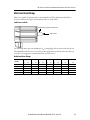
Motor Load Force Ratings
Motors are capable of operating with a sustained shaft load. The radial and axial load force
location is shown in the figure, and maximum values are in the tables.
Load Forces on Shaft
The following tables represent 20,000 hour L
10
bearing fatigue life at various loads and speeds.
This 20,000 hour life does not account for possible application-specific life reduction that can
occur due to bearing grease contamination from external sources.
Radial Load Force Ratings
Motor
Cat. No.
500 rpm 1000 rpm 2000 rpm 3000 rpm 3500 rpm 4000 rpm 5000 rpm
kg (lb) kg (lb) kg (lb) kg (lb) kg (lb) kg (lb) kg (lb)
MPL-A/B4560 151 (332) 119 (263) 95 (209) 83 (183) — — — — — —
MPL-A/B520 — — 127 (280) 100 (222) 88 (194) — — 80 (176) — —
MPL-A/B540 — — 143 (316) 114 (251) 99 (219) — — 90 (199) — —
MPL-A/B560 — — 153 (338) 121 (268) 106 (234) — — — — — —
MPL-B580 — — 153 (338) 121 (268) 106 (234) — — — — — —
Axial load force
Radial load force applied at center of shaft

18 Rockwell Automation Publication MP-IN001J-EN-P - June 2018
MP-Series Low-inertia Servo Motor with 100 mm to 165 mm Frame Size
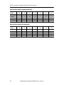
Axial Load Force Ratings (maximum radial load)
Axial Load Force Ratings (zero radial load)
Motor
Cat. No.
500 rpm 1000 rpm 2000 rpm 3000 rpm 3500 rpm 4000 rpm 5000 rpm
kg (lb) kg (lb) kg (lb) kg (lb) kg (lb) kg (lb) kg (lb)
MPL-A/B4560 53 (117) 40 (88) 30 (65) 24 (53) — — ————
MPL-A/B520 — — 42 (94) 30 (68) 26 (58) — — 22 (50) — —
MPL-A/B540 — — 48 (107) 35 (79) 30 (66) — — 26 (58) — —
MPL-A/B560 — — 52 (115) 43 (95) 32 (71) — — ————
MPL-B580 — — 52 (115) 43 (95) 32 (71) — — ————
Motor
Cat. No.
500 rpm 1000 rpm 2000 rpm 3000 rpm 3500 rpm 4000 rpm 5000 rpm
kg (lb) kg (lb) kg (lb) kg (lb) kg (lb) kg (lb) kg (lb)
MPL-A/B4560 69 (152) 51 (112) 38 (83) 31 (69) — —————
MPL-A/B520 — — 67 (149) 49 (109) 41 (92) — — 36 (81) — —
MPL-A/B540 — — 67 (149) 49 (109) 41 (92) — — 36 (81) — —
MPL-A/B560 — — 67 (149) 49 (109) 41 (92) — —————
MPL-B580 — — 67 (149) 49 (109) 41 (92) — —————

Rockwell Automation Publication MP-IN001J-EN-P - June 2018 19
MP-Series Low-inertia Servo Motor with 100 mm to 165 mm Frame Size
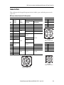
Connector Data
These tables provide the signal descriptions for the feedback, power, and brake pinouts on the
connectors.
MPL-xxxxx-xx2xxx Connector Pin Descriptions
Feedback Connector Power Connector
High-Resolution Encoder for: Pin Signal
2000-line 2-pole
MPL-A3xx Through
MPL-A45xx
MPL-A5xx, and all
MPL-B (460V)
APhase U
Pin Encoder Resolver BPhase V
A AM+ S2 SIN+ SIN+ C Phase W
B AM- S4 SIN- SIN- D Ground
C BM+ S1 COS+ COS+
D BM- S3 COS- COS-
EIM+
Reserved
DATA+ DATA+
FI-M DATA- DATA-
G Ground R1
Reserved
Reserved
HABS R2
JReserved
Reserved
K EPWR_5 V +5 VDC
LECOM Common
M
Reserved Reserved
Brake Connector
N +9 VDC Pin Signal
P Common A MBRK+
R TS+ TS+ TS+ TS+ B Reserved
S TS- TS- TS- TS- C MBRK-
TS1
Reserved Reserved Reserved
D Reserved
US2
VS3
A
B
C
D
ITT Cannon
TNM 16-4 192993-0106
A
B
C
D
ITT Cannon
TNM 10-4 192993-0116
A
B
C
D
E
F
G
H
J
K
L
M
N
P
R
S
T
U
V
ITT Cannon
TNM 16-19 192993-0110

20 Rockwell Automation Publication MP-IN001J-EN-P - June 2018
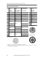
MP-Series Low-inertia Servo Motor with 100 mm to 165 mm Frame Size
MPL-xxxxx-xx7xxxx Pin Descriptions
Pin
High-Resolution
Encoder
High-Resolution
Encoder
Incremental Encoder
Pin
Power/Brake
Connector
MPL-A3xx to
MPL-A45xx (230V)
MPL-A5xx (230V) and
MPL-Bxx (460V)
MPL-A/Bxxxx-Hxxxx
MPL-Axxx and
MPL-Bxxx
1SIN+ SIN+ AM+ A Phase U
(2)
(2) Power pins A, B, C, and D can also be labeled as U, V, W, and GND respectively. Brake pins F and G brake can also be labeled as + and - respectively.
Reserved pins E and H can also be numbered 1 or 2.
2SIN- SIN- AM- BPhase V
(2)
3COS+ COS+ BM+ CPhase W
(2)
4 COS- COS- BM- D Ground
(2)
5 DATA+ DATA+ IM+ E Reserved
(2)
6 DATA- DATA- IM- F MBRK+
(2)
7
Reserved
Reserved
Reserved
GMBRK-
(2)
8H
Reserved
(2)
9EPWR_5V EPWR_5V L
(1)
(1) M23 (BEDC…) connector has nine pins, and the M40 (CEDE…) connector has eight pins.
10 ECOM ECOM
M23 Power/Brake Connector
M40 Power/Brake Connector
11
Reserved
EPWR_9V
Reserved
12 ECOM
13 TS+ TS+ TS+
14 TS- TS- TS-
15
Reserved Reserved
S1
16 S2
17 S3
M23 Feedback Connector
B C
A
G
L
F
E
H
D
V
UW
12
+
-
1
2
3
4
5
6
7
8
9
10
11
12
13
14
17
15
16
Page is loading ...
Page is loading ...
Page is loading ...
Page is loading ...
Page is loading ...
Page is loading ...
-
 1
1
-
 2
2
-
 3
3
-
 4
4
-
 5
5
-
 6
6
-
 7
7
-
 8
8
-
 9
9
-
 10
10
-
 11
11
-
 12
12
-
 13
13
-
 14
14
-
 15
15
-
 16
16
-
 17
17
-
 18
18
-
 19
19
-
 20
20
-
 21
21
-
 22
22
-
 23
23
-
 24
24
-
 25
25
-
 26
26


Allen-Bradley MPL-A310, MPL-A320, MPL-A330, MPL-A420, MPL-A430, MPL-A4530, MPL-A4540, MPL-A4560, MPL-A520, MPL-A540, MPL-A560, MPL-B310, MPL-B Installation Instructions Manual
- Type
- Installation Instructions Manual
Ask a question and I''ll find the answer in the document
Finding information in a document is now easier with AI
Related papers
-
Allen-Bradley MPL-A320 Installation Instructions Manual
-
Allen-Bradley Kinetix 2198-H015-ERS2 User manual
-
Allen-Bradley Kinetix 300 User manual
-
Allen-Bradley Kinetix 5700 User manual
-
Allen-Bradley 2099-BM09-S User manual
-
Allen-Bradley Kinetix 350 User manual
-
-
-
-
Other documents
-
 Rockwell Automation MPL-A320 Installation Instructions Manual
-
Mitsubishi Electric Rotary Servo Motor User manual
-
 Rockwell Automation Allen-Bradley Kinetix 5500 Migration Manual
-
Rockwell Automation MPF-B310 Installation Instructions Manual
-
Easypix 01424 Datasheet
-
-
 Rockwell Automation Allen-Bradley Kinetix 5700 Series Reference guide
-
 Rockwell Automation Allen-Bradley 2198-KTBT Installation guide
-
 Rockwell Automation Allen-Bradley 2198-H2DCK Installation guide
-
 Baldor-Reliance BSM Motor Quick start guide


