Page is loading ...

Kinetix 2000 Multi-axis Servo Drives to Kinetix 5500 Servo
Drives
Migration Guide

Important User Information
Read this document and the documents listed in the additional resources section about installation, configuration, and
operation of this equipment before you install, configure, operate, or maintain this product. Users are required to
familiarize themselves with installation and wiring instructions in addition to requirements of all applicable codes, laws,
and standards.
Activities including installation, adjustments, putting into service, use, assembly, disassembly, and maintenance are required
to be carried out by suitably trained personnel in accordance with applicable code of practice.
If this equipment is used in a manner not specified by the manufacturer, the protection provided by the equipment may be
impaired.
In no event will Rockwell Automation, Inc. be responsible or liable for indirect or consequential damages resulting from the
use or application of this equipment.
The examples and diagrams in this manual are included solely for illustrative purposes. Because of the many variables and
requirements associated with any particular installation, Rockwell Automation, Inc. cannot assume responsibility or
liability for actual use based on the examples and diagrams.
No patent liability is assumed by Rockwell Automation, Inc. with respect to use of information, circuits, equipment, or
software described in this manual.
Reproduction of the contents of this manual, in whole or in part, without written permission of Rockwell Automation,
Inc., is prohibited.
Throughout this manual, when necessary, we use notes to make you aware of safety considerations.
Labels may also be on or inside the equipment to provide specific precautions.
Allen-Bradley, Rockwell Automation, and Kinetix are trademarks of Rockwell Automation, Inc.
Trademarks not belonging to Rockwell Automation are property of their respective companies.
WARNING: Identifies information about practices or circumstances that can cause an explosion in a hazardous environment,
which may lead to personal injury or death, property damage, or economic loss.
ATTENTION: Identifies information about practices or circumstances that can lead to personal injury or death, property
damage, or economic loss. Attentions help you identify a hazard, avoid a hazard, and recognize the consequence.
IMPORTANT
Identifies information that is critical for successful application and understanding of the product.
SHOCK HAZARD: Labels may be on or inside the equipment, for example, a drive or motor, to alert people that dangerous
voltage may be present.
BURN HAZARD: Labels may be on or inside the equipment, for example, a drive or motor, to alert people that surfaces may
reach dangerous temperatures.
ARC FLASH HAZARD: Labels may be on or inside the equipment, for example, a motor control center, to alert people to
potential Arc Flash. Arc Flash will cause severe injury or death. Wear proper Personal Protective Equipment (PPE). Follow ALL
Regulatory requirements for safe work practices and for Personal Protective Equipment (PPE).

Rockwell Automation Publication 2093-AP001A-EN-P - May 2014 3
Table of Contents
Preface
Overview . . . . . . . . . . . . . . . . . . . . . . . . . . . . . . . . . . . . . . . . . . . . . . . . . . . . . . . . . . 7
Kinetix 5500 Servo Drives . . . . . . . . . . . . . . . . . . . . . . . . . . . . . . . . . . . . . . . . . . 8
Kinetix 5500 Servo Drive Features. . . . . . . . . . . . . . . . . . . . . . . . . . . . . . . . . . . 8
Kinetix 5500 Servo Drive Components . . . . . . . . . . . . . . . . . . . . . . . . . . . . . . 9
Kinetix 5500 Servo Drive Selection . . . . . . . . . . . . . . . . . . . . . . . . . . . . . . . . . . 9
Pre-migration . . . . . . . . . . . . . . . . . . . . . . . . . . . . . . . . . . . . . . . . . . . . . . . . . . . . 10
Additional Resources . . . . . . . . . . . . . . . . . . . . . . . . . . . . . . . . . . . . . . . . . . . . . 10
Chapter 1
Servo Drive and System
Considerations
Engineering Effort and Product Liability . . . . . . . . . . . . . . . . . . . . . . . . . . . 13
Communications . . . . . . . . . . . . . . . . . . . . . . . . . . . . . . . . . . . . . . . . . . . . . . . . 13
Controller, Ethernet Cards, and Switches . . . . . . . . . . . . . . . . . . . . . . . . . . 14
Motors . . . . . . . . . . . . . . . . . . . . . . . . . . . . . . . . . . . . . . . . . . . . . . . . . . . . . . . . . . 14
Cable Lengths . . . . . . . . . . . . . . . . . . . . . . . . . . . . . . . . . . . . . . . . . . . . . . . . . . . 15
Physical Dimensions. . . . . . . . . . . . . . . . . . . . . . . . . . . . . . . . . . . . . . . . . . . . . . 15
Control Power . . . . . . . . . . . . . . . . . . . . . . . . . . . . . . . . . . . . . . . . . . . . . . . . . . . 15
Circuit Protection. . . . . . . . . . . . . . . . . . . . . . . . . . . . . . . . . . . . . . . . . . . . . . . . 15
Control Signals . . . . . . . . . . . . . . . . . . . . . . . . . . . . . . . . . . . . . . . . . . . . . . . . . . 16
Safe Torque-off Safety Features. . . . . . . . . . . . . . . . . . . . . . . . . . . . . . . . . . . . 16
Accessories . . . . . . . . . . . . . . . . . . . . . . . . . . . . . . . . . . . . . . . . . . . . . . . . . . . . . . 16
Chapter 2
Servo Drive and System Comparisons
Drive Sizing . . . . . . . . . . . . . . . . . . . . . . . . . . . . . . . . . . . . . . . . . . . . . . . . . . . . . 18
Output Current Comparison. . . . . . . . . . . . . . . . . . . . . . . . . . . . . . . . . . 18
Dimension Comparison . . . . . . . . . . . . . . . . . . . . . . . . . . . . . . . . . . . . . . 19
Dimension Drawings . . . . . . . . . . . . . . . . . . . . . . . . . . . . . . . . . . . . . . . . . . . . . 20
Kinetix 2000 Servo Drive Dimensions – Integrated Axis Module . 20
Kinetix 2000 Servo Drive Dimensions – Axis Module . . . . . . . . . . . 20
Kinetix 5500 Servo Drive Dimensions. . . . . . . . . . . . . . . . . . . . . . . . . . 21
AC Input Power Wiring and Fusing . . . . . . . . . . . . . . . . . . . . . . . . . . . . . . . 22
AC Input Power Wiring . . . . . . . . . . . . . . . . . . . . . . . . . . . . . . . . . . . . . . 22
Circuit Breaker and Fuse Considerations . . . . . . . . . . . . . . . . . . . . . . . 28
Drive Interconnects and Cabling . . . . . . . . . . . . . . . . . . . . . . . . . . . . . . . . . . 32
Motor Power and Feedback . . . . . . . . . . . . . . . . . . . . . . . . . . . . . . . . . . . 32
Kinetix 2000 Servo Drives with MP-Series Low Inertia Motors. . . 32
2090-Series Single Motor Cable Overview . . . . . . . . . . . . . . . . . . . . . . 33
Kinetix 5500 (200V-class operation) Servo Drives with
Kinetix VP Low Inertia Motors . . . . . . . . . . . . . . . . . . . . . . . . . . 33
Kinetix 5500 (400V-class operation) Servo Drives with
Kinetix VP Low Inertia Motors . . . . . . . . . . . . . . . . . . . . . . . . . . 34
Kinetix 5500 Servo Drive Hiperface-to-DSL Feedback
Converter Kit . . . . . . . . . . . . . . . . . . . . . . . . . . . . . . . . . . . . . . . . . . 35
Digital Inputs. . . . . . . . . . . . . . . . . . . . . . . . . . . . . . . . . . . . . . . . . . . . . . . . . . . . 36
Kinetix 2000 Servo Drive Digital Inputs. . . . . . . . . . . . . . . . . . . . . . . . 36
Kinetix 5500 Servo Drive Digital Inputs. . . . . . . . . . . . . . . . . . . . . . . . 37

4 Rockwell Automation Publication 2093-AP001A-EN-P - May 2014
Table of Contents
Typical System Layout . . . . . . . . . . . . . . . . . . . . . . . . . . . . . . . . . . . . . . . . . . . . 38
Kinetix 2000 Servo System Example . . . . . . . . . . . . . . . . . . . . . . . . . . . . 38
Kinetix 5500 Servo Drive System Example . . . . . . . . . . . . . . . . . . . . . . 39
Accessories. . . . . . . . . . . . . . . . . . . . . . . . . . . . . . . . . . . . . . . . . . . . . . . . . . . . . . . 40
Kinetix 2000 Servo Drive Accessories. . . . . . . . . . . . . . . . . . . . . . . . . . . 40
Kinetix 5500 Servo Drive Accessories. . . . . . . . . . . . . . . . . . . . . . . . . . . 41
Appendix A
Connectors and Field Connections
Connector Locations . . . . . . . . . . . . . . . . . . . . . . . . . . . . . . . . . . . . . . . . . . . . . 43
Kinetix 2000 Servo Drive Connector Data. . . . . . . . . . . . . . . . . . . . . . 43
Kinetix 5500 Servo Drive Connector Data. . . . . . . . . . . . . . . . . . . . . . 45
Input Power Connector Pinouts . . . . . . . . . . . . . . . . . . . . . . . . . . . . . . . . . . . 46
Motor Power and Brake Pinouts . . . . . . . . . . . . . . . . . . . . . . . . . . . . . . . . . . . 47
Encoder Connector Pinouts . . . . . . . . . . . . . . . . . . . . . . . . . . . . . . . . . . . . . . . 48
I/O Connector Pinouts . . . . . . . . . . . . . . . . . . . . . . . . . . . . . . . . . . . . . . . . . . . 49
Appendix B
About the Servo Drive System
About the Kinetix 2000 Servo Drive System . . . . . . . . . . . . . . . . . . . . . . . . 51
About the Kinetix 5500 Servo Drive System . . . . . . . . . . . . . . . . . . . . . . . . 52
Appendix C
Specifications
Power Specifications . . . . . . . . . . . . . . . . . . . . . . . . . . . . . . . . . . . . . . . . . . . . . . 53
Kinetix 2000 Servo Drive Converter Power Specifications. . . . . . . . 53
Kinetix 2000 Servo Drive Inverter Power Specifications. . . . . . . . . . 54
Kinetix 5500 Servo Drive Input Power Specifications . . . . . . . . . . . . 55
Kinetix 5500 Servo Drive Output Power Specifications . . . . . . . . . . 56
Control Power Specifications. . . . . . . . . . . . . . . . . . . . . . . . . . . . . . . . . . . . . . 57
Kinetix 2000 Servo Drive Control Power Specifications. . . . . . . . . . 57
Kinetix 5500 Servo Drive Control Power Specifications. . . . . . . . . . 57
Power Dissipation Specifications. . . . . . . . . . . . . . . . . . . . . . . . . . . . . . . . . . . 58
Kinetix 2000 Servo Drive Power Dissipation Specifications . . . . . . 58
Kinetix 5500 Servo Drive Power Dissipation Specifications . . . . . . 58
Cable Lengths. . . . . . . . . . . . . . . . . . . . . . . . . . . . . . . . . . . . . . . . . . . . . . . . . . . . 59
Kinetix 2000 Servo Drive Feedback Cable Lengths . . . . . . . . . . . . . . 59
Kinetix 5500 Servo Drive Single Motor Cable Lengths. . . . . . . . . . . 59
Environmental Specifications. . . . . . . . . . . . . . . . . . . . . . . . . . . . . . . . . . . . . . 60
Kinetix 2000 Servo Drive Environmental Specifications. . . . . . . . . . 60
Kinetix 5500 Servo Drive Environmental Specifications. . . . . . . . . . 60
Certifications . . . . . . . . . . . . . . . . . . . . . . . . . . . . . . . . . . . . . . . . . . . . . . . . . . . . 61
Kinetix 2000 Servo Drive Certifications . . . . . . . . . . . . . . . . . . . . . . . . 61
Kinetix 5500 Servo Drive Certifications . . . . . . . . . . . . . . . . . . . . . . . . 61

Rockwell Automation Publication 2093-AP001A-EN-P - May 2014 5
Table of Contents
Appendix D
Interconnect Diagrams
Kinetix 2000 Servo Drive Examples. . . . . . . . . . . . . . . . . . . . . . . . . . . . . . . . 63
Power Wiring Examples. . . . . . . . . . . . . . . . . . . . . . . . . . . . . . . . . . . . . . . 63
DC Common Bus Wiring Examples . . . . . . . . . . . . . . . . . . . . . . . . . . . 66
Kinetix 5500 Servo Drive Power Wiring Examples . . . . . . . . . . . . . . . . . . 67
Single-axis Drive Wiring Examples . . . . . . . . . . . . . . . . . . . . . . . . . . . . . 67
Bus-sharing Wiring Examples . . . . . . . . . . . . . . . . . . . . . . . . . . . . . . . . . 69
Appendix E
Communication Configurations
Kinetix 5500 Servo Drive Linear Topology . . . . . . . . . . . . . . . . . . . . . . . . . 72
Kinetix 5500 Servo Drive Ring Topology . . . . . . . . . . . . . . . . . . . . . . . . . . 73
Kinetix 5500 Servo Drive Star Topology . . . . . . . . . . . . . . . . . . . . . . . . . . . 74

6 Rockwell Automation Publication 2093-AP001A-EN-P - May 2014
Table of Contents

Rockwell Automation Publication 2093-AP001A-EN-P - May 2014 7
Preface
Overview
The purpose of this migration guide is to provide you with the essential
information to determine what hardware design changes may be necessary when
migrating from a motion system containing Kinetix® 2000 servo drives to one
containing Kinetix 5500 servo drives.
This migration guide contains these chapters and appendices.
IMPORTANT
Migrating from a motion control system that uses Kinetix 2000 servo drives to a
system that uses Kinetix 5500 servo drives requires a comprehensive design
review of the entire motion control system. There are multiple drive
replacement combinations, multiple configurations for how the drives can be
installed, and how software is applied. In addition there are system wide
changes required because of the communication protocol employed.
As a result, this migration guide is not an all-inclusive document. It does not
describe all the redesign steps that may be required, nor does it contain the
detailed product information necessary to finalize the redesign. The
generalities of the replacement process are covered, and the decision-making
steps likely to be encountered in a typical replacement scenario are described.
You will need to review additional product literature (see Additional Resources
on page 10) to understand the technical similarities and differences between
the Kinetix 2000 servo drive and a Kinetix 5500 servo drive, and to help you
determine the proper solution for your migration.
Chapter 1: Servo Drive and System Considerations Describes some of the primary differences and system design
considerations between the drive families.
Chapter 2: Servo Drive and System Comparisons Provides information on drive sizing, dimension comparison,
input wiring / fusing, motor power, cabling, and system layout.
Appendix A: Connectors and Field Connections Provides information on connector locations, and comparisons
for encoder wiring, control wiring, and mains power wiring.
Appendix B: About the Servo Drive System
Provides cut-sheet information about both drive families.
Appendix C: Specifications
Provides comparisons of the power specifications, cable
lengths, environmental specifications, and certifications.
Appendix D: Interconnect Diagrams
Provides interconnect diagrams to assist in comparing power
wiring and drive connections for both drive families.
Appendix E: Communication Configurations
Provides communication topologies for Kinetix 5500 servo
drives.

8 Rockwell Automation Publication 2093-AP001A-EN-P - May 2014
Preface
Kinetix 5500 Servo Drives
The Kinetix 5500 servo drives and
Kinetix VP low-inertia servo motors
provide a cost-effective motion
solution that delivers high
performance and scalability with
motor windings matched to drive
ratings for optimized system sizing.
Enhancing the current midrange
architecture portfolio, this motion
system is designed to connect and
operate with the new family of
CompactLogix 5370 controllers by
using the Studio 5000 environment and supporting Integrated Motion on the
EtherNet/IP network. With the benefits of this motion system, you can now run
motion applications on a single control platform by using a single network—
simplifying the design, operation, and maintenance of equipment.
Kinetix 5500 Servo Drive
Features
The Kinetix 5500 servo drive provides the following features:
• High performance in a smaller footprint and optimized power density
• Single motor cable that includes power, feedback, and brake conductors
with SpeedTec connector
• Single-axis operation for low-cost simplicity
• Flexible power connectivity in multi-axis bus-sharing configurations
– Shared AC
– Shared DC
– Shared AC/DC and hybrid configurations
• Integrated motion on the EtherNet/IP network
• Safe torque-off control, ISO-13849-1 certified, PLd, category 3
• Versatile AC input voltag e range
– 195…264V rms, single-phase
– 195…264V rms, three-phase
– 324…528V rms, three-phase
• Bulletin VPL winding options that match the drive ratings for optimized
system sizing
– 0.2…14.6 kW continuous output power
– 1.4…32.5 A 0-pk, continuous output current (inverter)
• Bulletin 2198 capacitor module and Bulletin 2097 shunt resistor for
energy absorption management
• Digital (DSL) feedback device provides real-time motor performance
information to the control circuitry
– High-resolution absolute, multi-turn, and single-turn encoder feedback
• Capability to run servo and induction motors

Rockwell Automation Publication 2093-AP001A-EN-P - May 2014 9
Preface
Kinetix 5500 Servo Drive
Components
Kinetix 5500 servo drive systems consist of these required components:
• One 2198-H0xx-ERSx servo drive
• One Kinetix VP servo motor, induction motor, or MP-Series rotary motor
or linear actuator
– MP-Series compatibility requires 2198-H2DCK converter kit
• One 2090-CSxM1DF-xxAAxx motor cable for power, feedback, and
brake connections
• One 1606-XLxxx 24V power supply for control and motor brake power
• 1585J-M8CBJM-x (shielded) Ethernet cable
Kinetix 5500 servo drive systems can also include any of these optional
components:
• One 2198-CAPMOD-1300 capacitor module
• One 2198-DBxx-F AC line filter
• One 2097-Rx shunt resistor
• Bulletin 2198 shared-bus connection system
For detailed Kinetix 5500 servo drive system requirements, see the Kinetix 5500
Servo Drive Systems Design Guide, publication GMC-RM009
.
Kinetix 5500 Servo Drive
Selection
For Kinetix 5500 servo drive module specifications not included in this
publication, see the Kinetix Servo Drives Technical Data, publication GMC-
TD003.
Kinetix 5500
Servo Drive
Cat. No.
Frame
Size
Input Voltage Continuous
Output Power
kW
Continuous
Output Current
A 0-pk
2198-H003-ERSx
1
195…264V rms, single-phase
195…264V rms, three-phase
324…528V rms, three-phase
0.2 kW
0.3 kW
0.6 kW
1.4 A
2198-H008-ERSx
0.5 kW
0.8 kW
1.6 kW
3.5 A
2198-H015-ERSx
2
1.0 kW
1.5 kW
3.2 kW
7.1 A
2198-H025-ERSx
195…264V rms, three-phase
324…528V rms, three-phase
2.4 kW
5.1 kW
11.3 A
2198-H040-ERSx
4.0 kW
8.3 kW
18.4 A
2198-H070-ERSx 3
7.0 kW
14.6 kW
32.5 A

10 Rockwell Automation Publication 2093-AP001A-EN-P - May 2014
Preface
Pre-migration
Motion Analyzer software – is a comprehensive motion-application sizing tool
used for analysis, optimization, selection, and validation of your Kinetix motion
control system. This software facilitates the machine design process, letting you
quickly design and validate new machine concepts without purchasing or
installing physical equipment.
The performance capabilities of any replacement drive should be reviewed to be
sure that the replacement drive is capable of delivering the required level of peak
and continuous current to the motor and the Motion Analyzer software can assist
in the correct drive selection.
Download is available at http://ab.rockwellautomation.com/motion-control/
motion-analyzer-software.
Controller Files – Upload and save any network files and programmable logic
controller (PLC) programs.
Electrical Noise Reduction – See the System Design for Control of Electrical
Noise Reference Manual, publication GMC-RM001
, for information on the
concept of high-frequency (HF) bonding, the ground plane principle, and
electrical noise reduction.
Additional Resources
These documents contain additional information concerning related products
from Rockwell Automation.
Resource Description
Integrated Motion on SERCOS and EtherNet/IP Systems - Analysis and Comparison,
publication MOTION-WP001
Compare and contrast Integrated Motion systems using SERCOS and EtherNet/IP with
a ControlLogix® Programmable Automation Controller (PAC).
Ethernet Design Considerations Reference Manual, publication ENET-RM002
Provides information for designing ethernet and EtherNet/IP networks.
Kinetix 5500 Servo Drives User Manual, publication 2198-UM001
Information on installing, configuring, startup, troubleshooting, and applications for
your Kinetix servo drive system.
Kinetix 5500 Drive Systems Design Guide, publication GMC-RM009 System design guide to select the required (drive specific) drive module, power
accessory, feedback connector kit, and motor cable catalog numbers for your
Kinetix 5500 drive and Kinetix VP motor motion control system.
Logix 5000 Control Systems: Connect Kinetix 5500 Drives over an EtherNet/IP Network,
publication IASIMP-QS035
Provides examples and procedures for integrating a Kinetix 5500 servo drive into any
Logix 5000™ control system over an EtherNet/IP network.
Kinetix 5500 Servo Drives Installation Instructions, publication 2198-IN001
Information on mounting and wiring the Kinetix 5500 servo drive.
Kinetix 5500 Feedback Connector Kit Installation Instructions, publication 2198-IN002
Information on installing and wiring the Kinetix 5500 motor feedback connector kit.
Kinetix 5500 AC Line Filter Installation Instructions, publication 2198-IN003
Information on installing and wiring the Kinetix 5500 servo drive AC line filters.
Kinetix 5500 Capacitor Module Installation Instructions, publication 2198-IN004
Information on installing and wiring the Kinetix 5500 servo drive capacitor module.
Kinetix 5500 Shared-bus Connector Kit Installation Instructions, publication 2198-IN005
Information on installing the Kinetix 5500 servo drive shared-bus connector kits.
Kinetix 300 Shunt Resistor Installation Instructions, publication 2097-IN002 Information on installing and wiring Kinetix 300 shunt resistors.
System Design for Control of Electrical Noise Reference Manual, publication GMC-RM001
Information, examples, and techniques designed to minimize system failures caused
by electrical noise.
EMC Noise Management DVD, publication GMC-SP004
Kinetix Motion Control Selection Guide, publication GMC-SG001
Overview of Kinetix servo drives, motors, actuators, and motion accessories designed
to help make initial decisions for the motion control products best suited for your
system requirements.

Rockwell Automation Publication 2093-AP001A-EN-P - May 2014 11
Preface
You can view or download publications at http://www.rockwellautomation.com/
literature. To order paper copies of technical documentation, contact your local
Allen-Bradley® distributor or Rockwell Automation sales representative.
To find your local Rockwell Automation distributor or sales representative, visit
http://www.rockwellautomation.com/locations
.
Kinetix Rotary Motion Specifications Technical Data, publication GMC-TD001 Product specifications for Kinetix VP (Bulletin VPL), MP-Series™ (Bulletin MPL, MPM,
MPF, MPS), Kinetix 6000M (Bulletin MDF), TL-Series™, RDD-Series™, and HPK-Series™
rotary motors.
Kinetix Servo Drives Specifications Technical Data, publication GMC-TD003 Product specifications for Kinetix Integrated Motion over the EtherNet/IP network,
Integrated Motion over sercos interface, EtherNet/IP networking, and component
servo drive families.
Kinetix 2000 Multi-axis Servo Drives User Manual, publication 2093-UM001
Provides information on how to install, configure, startup, and troubleshoot your
Kinetix 2000 servo drive system.
Kinetix 2000 Integrated Axis Module and Axis Module Installation Instructions,
publication 2093-IN001
Information on installing the individual modules that comprise a Kinetix 2000 servo
drive system
Kinetix 2000 Shunt Module Installation Instructions, publication 2093-IN002
Kinetix 2000 Slot Filler Module Installation Instructions, publication 2093-IN003
Kinetix 2000 Power Rail Installation Instructions, publication 2093-IN004
Resource Description

12 Rockwell Automation Publication 2093-AP001A-EN-P - May 2014
Preface
Notes:

Rockwell Automation Publication 2093-AP001A-EN-P - May 2014 13
Chapter
1
Servo Drive and System Considerations
Replacing a Kinetix 2000 servo drive with a Kinetix 5500 servo drive will require
some system design changes as well as drive hardware changes. This chapter
describes some of the primary differences and considerations. Additional chapters
will provide in-depth drive comparisons.
Engineering Effort and
Product Liability
Thoroughly review this document before you begin to evaluate the design
changes required to successfully migrate your Kinetix 2000 servo drive to a
Kinetix 5500 servo drive.
The following sections highlight the major and minor differences between Kinetix
2000 servo drives and Kinetix 5500 servo drives. There may be more differences
beyond these that can impact your application. Read this entire document before
proceeding to qualify the Kinetix 5500 servo drive for your needs.
Communications
The Kinetix 2000 servo drives use the SERCOS network for communications. A
SERCOS interface module serves as a link between the ControlLogix/
CompactLogix platform and the Kinetix 2000 servo drive system.
The communication link uses the IEC 61491 SErial Real-time COmmunication
System (SERCOS) protocol over a fiber-optic media.
The Kinetix 5500 servo drives use the EtherNet/IP network for communicating
to either a ControlLogix or CompactLogix programmable automation controller.
All Kinetix 5500 servo drives include dual-port Ethernet/IP connectivity.
Supported Ethernet topologies include linear, ring, and star.
For more information on Ethernet design considerations, see these publications:
• Scalability - The Best Approach to Change, publication IA-WP002
ATTENTION: Because of the variety of uses for the products described in this
publication, those responsible for the application and use of these products
must satisfy themselves that all necessary steps have been taken to assure that
each application and use meets all performance and safety requirements,
including any applicable laws, regulations, codes, and standards. In no event
will Rockwell Automation be responsible or liable for indirect or consequential
damage resulting from the use or application of these products.

14 Rockwell Automation Publication 2093-AP001A-EN-P - May 2014
Chapter 1 Servo Drive and System Considerations
• EtherNet/IP Design, Commissioning, and Troubleshooting Quick
Reference, publication IASIMP-QR023
• Integrated Motion on EtherNet/IP Configuration Drawing with Notes,
publication IASIMP-QR019
See Appendix
E for communication configurations.
Controller, Ethernet Cards,
and Switches
The following table lists the compatible hardware for Integrated Motion on
EtherNet/IP systems.
Motors
Verify that your existing motor is compatible with the Kinetix 5500 servo drive
family. Kinetix 5500 servo drives are compatible with the following motors:
• Kinetix VP series servo motor
• Induction motors
• MP-Series rotary motors
• MP-Series linear actuators
Note: MP-Series compatibility requires a 2198-H2DCK converter kit, and also
requires drive firmware revision 2.001 or later, and the Kinetix 5500 servo drive
AOP (Add-On Profile) for Studio 5000 Logix Designer™ application, version
21.00.00 or later.
For more information, see Hiperface-to-DSL Feedback Converter Kit
Installation Instructions, publication 2198-IN006
.
For Kinetix 5500 Hiperface-to-DSL Feedback Converter Kit pin-out, see
page 35
.
In most cases encompass partner motors will work with the converter kit. Check
with your local Rockwell sales person or distributor to evaluate compatibility.
Hardware Description
Controllers ControlLogix® 1756 L7x and L6x models
CompactLogix® 5370 L3y, L2y, and L1y models
Ethernet Communication 1756-EN2T, 1756-EN2TR, and 1756-EN3TR
Ethernet Switches Stratix 8300™ Layer 3 Modular Managed Ethernet Switches
Stratix 8000™ Modular Managed Ethernet Switches
Stratix 6000™ Fixed Managed Ethernet Switches
Stratix 5700™ Managed Industrial Ethernet Switches
Stratix 2000™ Unmanaged Ethernet Switches

Rockwell Automation Publication 2093-AP001A-EN-P - May 2014 15
Servo Drive and System Considerations Chapter 1
Cable Lengths
Verify that the feedback cable length in your current Kinetix 2000 servo drive
system does not exceed the maximum cable lengths for the Kinetix 5500 servo
drives. The follow are maximum cable lengths for the Kinetix 5500 servo drives:
• Combined motor power cable length for all axes on the same DC bus must
not exceed 250 m (820 ft). Drive-to-motor cables must not exceed 50 m
(164 ft), however use of continuous-flex cable limits the maximum length.
See the Kinetix 5500 Servo Drives User Manual, publication
2198-UM001
, Table 5 for specifications by frame size.
• Ethernet cable lengths connecting drive-to-drive, drive-to-controller, or
drive-to-switch must not exceed 100 m (328 ft). Complete a careful
evaluation of your Ethernet media when using a CIP motion solution. For
more information, see Guidance for Selecting Cables for EtherNet/IP
Networks, publication ENET-WP007
.
• Registration and digital input cables greater than 30 m (98.4 ft) must be
shielded.
See Drive Interconnects and Cabling
on page 32 for more information.
Physical Dimensions
The physical size of the drive families are different (see Dimension Comparison
on page 19). In most cases, the Kinetix 5500 servo drives are smaller and will fit
into the existing space of the compatible Kinetix 2000 drives; however, you
should verify the physical size of the Kinetix 5500 servo drive.
Control Power
The Kinetix 2000 servo drive integrated axis module (IAM) requires AC input
power (230V AC nominal, single phase) for logic circuitry.
The Kinetix 5500 servo drive requires 24V DC input power for control circuitry.
You need to review your control power scheme including 24V power supply
requirements. See Appendix
C for more information on control power
specifications.
Circuit Protection
Sizing for protective devices, such as fuses and circuit breakers, may be different
between Kinetix 2000 servo drives and Kinetix 5500 servo drives. Verify that you
have chosen the correct sizes when selecting and installing a Kinetix 5500 servo
drive. For more information, see Appendix
C.

16 Rockwell Automation Publication 2093-AP001A-EN-P - May 2014
Chapter 1 Servo Drive and System Considerations
Control Signals
Digital Inputs – It is important to note that the Digital I/O function between
the Kinetix 2000 servo drive and Kinetix 5500 servo drive is different.
The Kinetix 2000 servo drive includes six digital inputs. They are Enable, Home,
Reg1, Reg2, OT+, and OT-. The drive supplies 24V DC @ 300 mA total for the
digital I/O.
The Kinetix 5500 servo drive includes two digital inputs. They are Reg1 and
Reg2. The Reg1 input is capable of dual functionality; it can also be used as the
Home input. Digital inputs require a 24V DC @ 15 mA supply and should be
considered in power supply sizing.
Contactor Enable Relay – The Kinetix 5500 servo drive does not have a
Contactor Enable Relay.
Dual Position Loop / Aux Feedback Port – The Kinetix 5500 servo drive does
not have the ability to accept an auxiliary encoder input for dual-loop operation
or to be used as a Master Input for encoder feedback.
If a Master Encoder input is required, other options are available such as using a
Bulletin 842E-CM Integrated Motion on EtherNet/IP™ Absolute Encoder that
provides a CIP Motion-capable Master Encoder that can be used with the Kinetix
5500 servo drive or investigate using a Kinetix 6200 or 6500 drive.
Motor Brake – Both servo drive families require a customer-supplied 24V power
source for motor-parking brake.
Safe Torque-off Safety
Features
Kinetix 5500 servo drives have the capability to safely turn off the inverter power
transistors in response to a monitored digital input, according to Category 0 Stop
behavior. These drives support parallel input terminals for cascading to adjacent
drives over duplex wiring.
For applications that do not require the safety function, you must install jumper
wires to bypass the safe torque-off feature.
For the Safe Torque-off connector pinout, installation, and wiring information,
see the related chapter in the Kinetix 5500 Servo Drives User Manual,
publication 2198-UM001
.
Accessories
Kinetix 2000 servo drive accessories include the 2093 shunt module, slot-filler
modules, line interface module, and AC line filter.
Kinetix 5500 servo drive accessories include the Bulletin 2198 capacitor module,
AC line filters, and the shared-bus connection system. Kinetix 5500 servo drives
are also compatible with Bulletin 2097 external shunt resistors. See Accessories
on page 40.

Rockwell Automation Publication 2093-AP001A-EN-P - May 2014 17
Chapter
2
Servo Drive and System Comparisons
There are a number of different factors that affect the selection of a replacement
servo drive and the system redesign effort. They include the following:
• Drive Sizing
• Dimension Comparison
• AC Input Power Wiring and Fusing
• Interconnects and Cabling
• Typical System Layout
• Accessories
This chapter provides a side-by-side comparison of both servo drive families to
help in the evaluation and selection of the correct components in the migration
process.

18 Rockwell Automation Publication 2093-AP001A-EN-P - May 2014
Chapter 2 Servo Drive and System Comparisons
Drive Sizing
This section lists the Kinetix 2000 servo drives and the suggested Kinetix 5500
replacement servo drives, along with the output ratings and dimension
differences of the drives. Information in this migration guide is based on the drive
combinations shown in Tab le 1
and Ta b le 2 .
Output Current Comparison
Table 1 - Suggested Kinetix 5500 Replacement Drives by Output Current
IMPORTANT
The performance capabilities of the replacement drive should be reviewed to
be sure that the replacement drive is capable of delivering the required level of
peak and continuous current to the motor.
Kinetix 2000 Servo Drives Kinetix 5500 Servo Drives
Model Voltage Range
(V)
Nominal
Voltage Range
(V)
Output
Current Rating
(0-pk) A
(1)
Recommended Kinetix
5500 Replacement Drive
Voltage Range
(V)
Nominal
Voltage Range
(V)
Output
Current Rating
(0-pk) A
(1)
2093-AC05-MP1 (IAM)
2093-AMP1
170...264, 1-phase
170...264, 3-phase
230, 1-phase
230, 3-phase
1.4 2198-H003-ERSx 195...264, 1-phase
195...264, 3-phase
324...528, 3-phase
240, 1-phase
240, 3-phase
480, 3-phase
1.4
2093-AC05-MP2 (IAM)
2093-AMP2
170...264, 1-phase
170...264, 3-phase
230, 1-phase
230, 3-phase
2.8 2198-H008-ERSx 195...264, 1-phase
195...264, 3-phase
324...528, 3-phase
240, 1-phase
240, 3-phase
480, 3-phase
3.5
2093-AC05-MP5 (IAM)
2093-AMP5
170...264, 1-phase
170...264, 3-phase
230, 1-phase
230, 3-phase
4.2 2198-H015-ERSx 195...264, 1-phase
195...264, 3-phase
324...528, 3-phase
240, 1-phase
240, 3-phase
480, 3-phase
7.1
2093-AM01 N/A N/A 8.5 2198-H025-ERSx 195...264, 3-phase
324...528, 3-phase
240, 3-phase
480, 3-phase
11.3
2093-AM02 N/A N/A 13.4 2198-H040-ERSx 195...264, 3-phase
324...528, 3-phase
240, 3-phase
480, 3-phase
18.4
N/A N/A N/A N/A 2198-H070-ERSx 195...264, 3-phase
324...528, 3-phase
240, 3-phase
480, 3-phase
32.5
(1) Continuous output current ratings are used.

Rockwell Automation Publication 2093-AP001A-EN-P - May 2014 19
Servo Drive and System Comparisons Chapter 2
Dimension Comparison
The following table provides a comparison of the dimensions of the drives.
Table 2 - Suggested Kinetix 5500 Replacement Drives by Dimensions
Kinetix 2000 Servo Drive
(1)
Kinetix 5500 Servo Drive Dimension Differences
Model Height
mm (in)
Width
mm (in)
Depth
mm (in)
Model Height
mm (in)
Width
mm (in)
Depth
mm (in)
Height
(2)
mm
Width
(2)
mm
Depth
(2)
mm
2093-AC05-MP1 (IAM) 225 (8.8) 90 (3.5) 192 (7.5)
2198-H003-ERSx 215 (8.46) 50 (1.97) 226 (8.90)
-10 -40 34
2093-AMP1 225 (8.8) 40 (1.6) 192 (7.5) -10 10 34
2093-AC05-MP2 (IAM) 225 (8.8) 90 (3.5) 192 (7.5)
2198-H008-ERSx 215 (8.46) 50 (1.97) 226 (8.90)
-10 -40 34
2093-AMP2 225 (8.8) 40 (1.6) 192 (7.5) -10 10 34
2093-AC05-MP5 (IAM) 225 (8.8) 90 (3.5) 192 (7.5)
2198-H015-ERSx 265 (10.43) 55 (2.16) 226 (8.90)
40 -35 34
2093-AMP5 225 (8.8) 40 (1.6) 192 (7.5) 40 15 34
2093-AM01 225 (8.8) 80 (3.1) 192 (7.5) 2198-H025-ERSx 265 (10.43) 55 (2.16) 226 (8.90) 40 -25 34
2093-AM02 225 (8.8) 80 (3.1) 192 (7.5) 2198-H040-ERSx 265 (10.43) 55 (2.16) 226 (8.90) 40 -25 34
N/A — — — 2198-H070-ERSx 294 (11.57) 8.52 (3.35) 226 (8.90) N/A N/A N/A
(1) Dimensions include the motor feedback connector.
(2) A minus sign denotes that the height, width, or depth of the Kinetix 5500 servo drive is shorter, narrower, or shallower than the comparable Kinetix 2000 servo drive.

20 Rockwell Automation Publication 2093-AP001A-EN-P - May 2014
Chapter 2 Servo Drive and System Comparisons
Dimension Drawings
This section provides dimensions of the drives to assist you in determining the
space needed to install the drives.
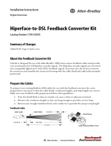
Kinetix 2000 Servo Drive Dimensions – Integrated Axis Module
Kinetix 2000 Servo Drive Dimensions – Axis Module
167.5
(6.6)
90
(3.5)
225
(8.8)
173
(6.8)
192
(7.5)
Power
Rail
Dimensions are in mm (in.)
192
(7.5)
80
(3.1)
40
(1.6)
167.5
(6.6)
225
(8.8)
173
(6.8)
Power
Rail
Dimensions are in mm (in.)
/