Page is loading ...

Industrial Process Controller
Model PC200
CTL-UM-00483-EN-07 (April 2017)
User Manual

Industrial Process Controller, Model PC200
Page ii April 2017CTL-UM-00483-EN-07

CONTENTS
Scope of This Manual . . . . . . . . . . . . . . . . . . . . . . . . . . . . . . . . . . . . . . . . . . . . . . . . . . . . . . . . . . . . . . . . . . . 5
Unpacking the PC200. . . . . . . . . . . . . . . . . . . . . . . . . . . . . . . . . . . . . . . . . . . . . . . . . . . . . . . . . . . . . . . . . . . 5
Safety Considerations. . . . . . . . . . . . . . . . . . . . . . . . . . . . . . . . . . . . . . . . . . . . . . . . . . . . . . . . . . . . . . . . . . . 5
Safety Terminology and Symbols. . . . . . . . . . . . . . . . . . . . . . . . . . . . . . . . . . . . . . . . . . . . . . . . . . . . . . . . . 5
Safety Instructions . . . . . . . . . . . . . . . . . . . . . . . . . . . . . . . . . . . . . . . . . . . . . . . . . . . . . . . . . . . . . . . . . . 6
Disposal . . . . . . . . . . . . . . . . . . . . . . . . . . . . . . . . . . . . . . . . . . . . . . . . . . . . . . . . . . . . . . . . . . . . . . . . 6
Safety Rules and Precautionary Measures . . . . . . . . . . . . . . . . . . . . . . . . . . . . . . . . . . . . . . . . . . . . . . . . . . . 6
PC200 Batch Controller Description. . . . . . . . . . . . . . . . . . . . . . . . . . . . . . . . . . . . . . . . . . . . . . . . . . . . . . . . . . 7
Functions and Features . . . . . . . . . . . . . . . . . . . . . . . . . . . . . . . . . . . . . . . . . . . . . . . . . . . . . . . . . . . . . . . 7
Flow Meter Input. . . . . . . . . . . . . . . . . . . . . . . . . . . . . . . . . . . . . . . . . . . . . . . . . . . . . . . . . . . . . . . . . . . 7
Control Inputs. . . . . . . . . . . . . . . . . . . . . . . . . . . . . . . . . . . . . . . . . . . . . . . . . . . . . . . . . . . . . . . . . . . . . 7
Control Outputs . . . . . . . . . . . . . . . . . . . . . . . . . . . . . . . . . . . . . . . . . . . . . . . . . . . . . . . . . . . . . . . . . . . 7
Power Supply . . . . . . . . . . . . . . . . . . . . . . . . . . . . . . . . . . . . . . . . . . . . . . . . . . . . . . . . . . . . . . . . . . . . . 7
Conguration of the Unit. . . . . . . . . . . . . . . . . . . . . . . . . . . . . . . . . . . . . . . . . . . . . . . . . . . . . . . . . . . . . . 8
Display Information . . . . . . . . . . . . . . . . . . . . . . . . . . . . . . . . . . . . . . . . . . . . . . . . . . . . . . . . . . . . . . . . . 8
Installation. . . . . . . . . . . . . . . . . . . . . . . . . . . . . . . . . . . . . . . . . . . . . . . . . . . . . . . . . . . . . . . . . . . . . . . . . . 9
Installation Conditions . . . . . . . . . . . . . . . . . . . . . . . . . . . . . . . . . . . . . . . . . . . . . . . . . . . . . . . . . . . . . . . 9
Mounting the PC200 . . . . . . . . . . . . . . . . . . . . . . . . . . . . . . . . . . . . . . . . . . . . . . . . . . . . . . . . . . . . . . . . 9
Wiring the PC200 . . . . . . . . . . . . . . . . . . . . . . . . . . . . . . . . . . . . . . . . . . . . . . . . . . . . . . . . . . . . . . . . . . . . 11
Voltage Selection Sensor Supply . . . . . . . . . . . . . . . . . . . . . . . . . . . . . . . . . . . . . . . . . . . . . . . . . . . . . . . . 11
Terminal Connectors . . . . . . . . . . . . . . . . . . . . . . . . . . . . . . . . . . . . . . . . . . . . . . . . . . . . . . . . . . . . . . . 11
Operation . . . . . . . . . . . . . . . . . . . . . . . . . . . . . . . . . . . . . . . . . . . . . . . . . . . . . . . . . . . . . . . . . . . . . . . . . 17
Control Panel . . . . . . . . . . . . . . . . . . . . . . . . . . . . . . . . . . . . . . . . . . . . . . . . . . . . . . . . . . . . . . . . . . . . 17
Operator Information and Functions . . . . . . . . . . . . . . . . . . . . . . . . . . . . . . . . . . . . . . . . . . . . . . . . . . . . . 18
Operator Alarms . . . . . . . . . . . . . . . . . . . . . . . . . . . . . . . . . . . . . . . . . . . . . . . . . . . . . . . . . . . . . . . . . . 20
Conguration. . . . . . . . . . . . . . . . . . . . . . . . . . . . . . . . . . . . . . . . . . . . . . . . . . . . . . . . . . . . . . . . . . . . . . . 21
Programming the Setup Level . . . . . . . . . . . . . . . . . . . . . . . . . . . . . . . . . . . . . . . . . . . . . . . . . . . . . . . . . 21
Transmitter Connections . . . . . . . . . . . . . . . . . . . . . . . . . . . . . . . . . . . . . . . . . . . . . . . . . . . . . . . . . . . . . 27
Transmitter Pulses Per Unit . . . . . . . . . . . . . . . . . . . . . . . . . . . . . . . . . . . . . . . . . . . . . . . . . . . . . . . . . . . 28
Maintenance . . . . . . . . . . . . . . . . . . . . . . . . . . . . . . . . . . . . . . . . . . . . . . . . . . . . . . . . . . . . . . . . . . . . . . . 29
Repair . . . . . . . . . . . . . . . . . . . . . . . . . . . . . . . . . . . . . . . . . . . . . . . . . . . . . . . . . . . . . . . . . . . . . . . . . 29
Technical Specications . . . . . . . . . . . . . . . . . . . . . . . . . . . . . . . . . . . . . . . . . . . . . . . . . . . . . . . . . . . . . . . . 30
General . . . . . . . . . . . . . . . . . . . . . . . . . . . . . . . . . . . . . . . . . . . . . . . . . . . . . . . . . . . . . . . . . . . . . . . . 30
Troubleshooting . . . . . . . . . . . . . . . . . . . . . . . . . . . . . . . . . . . . . . . . . . . . . . . . . . . . . . . . . . . . . . . . . . . . . 32
Record of Conguration Settings . . . . . . . . . . . . . . . . . . . . . . . . . . . . . . . . . . . . . . . . . . . . . . . . . . . . . . . . . . 33
User Manual
Page iii April 2017 CTL-UM-00483-EN-07

Industrial Process Controller, Model PC200
Page iv April 2017CTL-UM-00483-EN-07

SCOPE OF THIS MANUAL
This manual is divided into two main sections:
• The daily use of the unit is described in “Operation” on page17. These instructions are meant for users.
• The remaining chapters provide a detailed description of all software settings and hardware installation guidance. These
instructions and are meant exclusively for electricians/technicians.
This manual describes the standard unit as well as most of the options available. For additional information, please contact
your supplier.
MPORTANTI
Read this manual carefully before attempting any installation or operation.
Keep the manual in an accessible location for future reference.
UNPACKING THE PC200
OTE:N If damage to the shipping container is obvious, request that the carrier be present when the product is unpacked. All
claims for equipment damage during transit are the sole responsibility of the recipient.
After carefully unpacking the unit, check for any visible sign of damage. If found, notify the carrier for insurance purposes and
call the factory for possible replacement. Keep all packing material in the event that the unit must be returned to the factory.
OTE:N Operating temperature is 32…130° F (0…55° C) with a maximum humidity of 85% non-condensing. Always select a
mounting location with proper ventilation and environmental protection.
SAFETY CONSIDERATIONS
Safety Terminology and Symbols
Indicates a hazardous situation, which, if not avoided, is estimated to be capable of causing death or serious personal injury.
Indicates a hazardous situation, which, if not avoided, could result in severe personal injury or death.
Indicates a hazardous situation, which, if not avoided, is estimated to be capable of causing minor or moderate personal
injury or damage to property.
User Manual
Page 5 April 2017 CTL-UM-00483-EN-07

Safety Instructions
• LIFE SUPPORT APPLICATIONS: THE PC200 IS NOT DESIGNED FOR USE IN LIFE SUPPORT APPLIANCES, DEVICES, OR
SYSTEMS WHERE MALFUNCTION OF THE PRODUCT CAN REASONABLY BE EXPECTED TO RESULT IN A PERSONAL
INJURY. CUSTOMERS USING OR SELLING THESE PRODUCTS FOR USE IN SUCH APPLICATIONS DO SO AT THEIR OWN RISK
AND AGREE TO FULLY INDEMNIFY THE MANUFACTURER AND SUPPLIER FOR ANY DAMAGES RESULTING FROM SUCH
IMPROPER USE OR SALE.
• ELECTROSTATIC DISCHARGE INFLICTS IRREPARABLE DAMAGE TO ELECTRONICS! BEFORE INSTALLING OR OPENING THE
UNIT, INSTALLERS MUST DISCHARGE THEMSELVES BY TOUCHING A WELL-GROUNDED OBJECT.
• THIS UNIT MUST BE INSTALLED IN ACCORDANCE WITH THE EMC (ELECTROMAGNETIC COMPATIBILITY) GUIDELINES.
• CONNECT A PROPER GROUNDING TO THE ALUMINUM CASING AS INDICATED.
Disposal
Dispose of this product according to local regulations regarding waste electronic equipment. The separate collection and
recycling of your waste equipment will help to conserve natural resources and ensure that it is recycled in a manner that
protects the environment.
Safety Rules and Precautionary Measures
The manufacturer accepts no responsibility whatsoever if the following safety rules and precaution instructions and the
procedures as described in this manual are not followed.
• Modifications of the PC200 implemented without preceding written consent from the manufacturer will result in the
immediate termination of product liability and warranty period.
• Installation, use, maintenance, and servicing of this equipment must be carried out by authorized technicians.
• Check the mains voltage and information on the manufacturer's plate before installing the unit.
• Check all connections, settings and technical specifications of the various peripheral devices with the PC200 supplied.
• Open the casing only if all leads are free of potential.
• Never touch the electronic components (ESD sensitivity).
• Never expose the system to heavier conditions than allowed according to the casing classification (see manufacturer's
plate and “Installation Conditions” on page9).
• If the operator detects errors or dangers, or disagrees with the safety precautions taken, then inform the owner or
principal responsible.
• Adhere to the local labor and safety laws and regulations.
Industrial Process Controller, Model PC200
Page 6 April 2017CTL-UM-00483-EN-07

PC200 BATCH CONTROLLER DESCRIPTION
Functions and Features
The batch controller model PC200 is a microprocessor-driven instrument designed for batching and filling both small and
large quantities, as well as displaying total, accumulated total and flow rate.
This product is designed with a focus on:
• Ease-of-use with the numerical keyboard.
• Ruggedness for its application with a robust enclosure, keyboard and proper mechanical relays.
• Clear operator information: all relevant data can be monitored in one glance.
• User-friendly installation with quality plug-and-play terminals; suitable for both AC and DC applications (standard).
• A wide range of inputs, outputs and functions for a broad fulfillment in many applications.
Flow Meter Input
One flow meter: a passive or active pulse signal output can be connected to the PC200. The input circuit supports low and
high frequency flow meters. A power supply is available to power the sensor with 8 / 12 or 24V DC.
Control Inputs
The PC200 has six control inputs:
• Start
• Hold
• Resume
• Reset totalizer
• Reset cycle counter
• Lockout the entire keyboard
Control Outputs
The PC200 has five control outputs—two mechanical relay outputs and three transistor outputs. The two mechanical relay
outputs (make and break) are used for batching with two-stage control or one-stage control. Three transistor outputs are for
connection to PLCs or other controlling equipment. The function of relay R2 and the transistor outputs can be configured to:
• Batching
• Two-stage control
• High flow rate alarm
• Low flow rate alarm
• No-flow alarm
• Any alarm
• Scaled pulse output
• Pre-warn or end of batch signal
Power Supply
AC power supply: as standard, the PC200 will operate on 110…230V AC.
DC power supply: as standard, the PC200 can also operate on 24V DC.
User Manual
Page 7 April 2017 CTL-UM-00483-EN-07

Conguration of the Unit
The PC200 is designed for many types of applications. Use the SETUP level to configure your PC200 to your specific
requirements. For details, see “Configuration” on page21 and “Record of Configuration Settings” on page33.
The SETUP level includes several important features, such as K-factors, measurement units and selection of the control
outputs. All settings are stored in EEPROM memory and will not be lost in the event of power failure.
Display Information
The PC200 has a large transflective LCD with a bright LED backlight and displays symbols and digits for measuring units,
status information and keyword messages.
All total, accumulated total and batch counter information is stored in EEPROM memory and will not be lost in the event of
power failure.
Industrial Process Controller, Model PC200
Page 8 April 2017CTL-UM-00483-EN-07

INSTALLATION
• MOUNTING, ELECTRICAL INSTALLATION, STARTUP AND MAINTENANCE OF THIS INSTRUMENT MAY ONLY BE CARRIED
OUT BY TRAINED PERSONNEL AUTHORIZED BY THE OPERATOR OF THE FACILITY. PERSONNEL MUST READ AND
UNDERSTAND THIS OPERATING MANUAL BEFORE CARRYING OUT ITS INSTRUCTIONS.
• THE PC200 MAY ONLY BE OPERATED BY PERSONNEL WHO ARE AUTHORIZED AND TRAINED BY THE OPERATOR OF THE
FACILITY. OBSERVE ALL INSTRUCTIONS IN THIS MANUAL.
• ENSURE THAT THE MEASURING SYSTEM IS CORRECTLY WIRED ACCORDING TO THE WIRING DIAGRAMS. PROTECTION
AGAINST ACCIDENTAL CONTACT IS NO LONGER ASSURED WHEN THE HOUSING COVER IS REMOVED OR THE PANEL
CABINET HAS BEEN OPENED (DANGER FROM ELECTRICAL SHOCK). THE HOUSING MAY ONLY BE OPENED BY
TRAINED PERSONNEL.
• OBEY ALL SAFETY PRECAUTIONS MENTIONED IN “Safety Considerations” on page5.
Installation Conditions
Figure 1: Acceptable installation conditions
Consider the IP classification of the casing (see the manufacturer's plate) when selecting a location for the PC200. An IP65
(NEMA 4X) casing should NEVER be exposed to weather conditions.
When used in very cold surroundings or varying climatic conditions, take the necessary precautions against moisture by
placing a dry sachet of silica gel, or similar material, inside the instrument case.
Mounting the PC200
Mount the PC200 on a solid structure to avoid vibrations. The basic unit is equipped for panel mount. To install:
1. Measure and cut the mounting hole to the dimensions shown in Figure 2 on page 10.
2. Install the gasket around the mounting bezel.
3. Insert the unit through the front panel cutout.
4. Secure the unit to the panel with the mounting clips.
User Manual
Page 9 April 2017 CTL-UM-00483-EN-07

Figure 2: Enclosure dimensions
Figure 3: Grounding location, top view
MPORTANTI
Installations must have a reliable ground connection for the sensor and the metal casing.
Installations must have an effective screened cable for the input signal and grounding of its screen to the ground terminal or at the
sensor itself, whichever is appropriate to the application.
Figure 4: Grounding location, bottom view
Industrial Process Controller, Model PC200
Page 10 April 2017CTL-UM-00483-EN-07

WIRING THE PC200
At installation, be sure to comply with the following requirements:
• Disconnect power to the unit before attempting any connection or service to the unit.
• Avoid using machine power service for AC power. When possible, use a dedicated or lighting circuit.
• Do not bundle or route signal lines with power lines.
• Keep all lines as short as possible.
• Use shielded wire for all input wiring.
• Observe all local electrical codes.
TO PREVENT ACCIDENTS, POWER SHOULD NOT BE APPLIED UNTIL ALL OTHER CONNECTIONS HAVE BEEN COMPLETED.
Voltage Selection Sensor Supply
Sensor supply
8.2…12 or 24V DC
A power supply for the sensor is available. The flow meter can be powered with 8.2, 12 or 24V DC.
Total power consumption
Max. 50 mA @ 24V
The voltage is selected with the two switches at the rear of the enclosure.
Figure 5: Switch setting sensor supply voltage
Switch positions
Voltage Selection
Switch 1 Switch 2 Voltage
on on 24V DC
on off 8.2V DC
off off 12V DC
Table 1: Switch positions
Terminal Connectors
Figure 6: Overview of terminal connectors
User Manual
Page 11 April 2017 CTL-UM-00483-EN-07

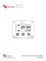
Terminal #01-02; lock keyboard:
Use the LOCK KEYBOARD function to connect a lock or jumper in order to disable the complete keyboard while the functions
from the terminals remain available. Certain keys on the keyboard can be locked-out with SETUP 85 or passcode-protected
with SETUP 84. Terminal #11 can block the batch process.
Terminal #03-07; flow meter input:
• A high or low frequency NPN signal can be connected to the PC200. For low frequency sensors like a reed switch, a low
pass filter on terminal #07 eliminates contact bounce. For higher frequencies, use terminal #06.
• Use terminal #05 for a 12V DC sensor supply. Use terminal #29 for 8.1, 12 or 24V DC.
• The screen of the signal wire must be connected to the common ground terminal #03 (unless earthed at the sensor itself).
Terminal #04 is not used.
• Active signals switching between 0…8V DC, 0…12V DC or 0…24V DC can be connected as well.
INTERNAL EXTERNAL
Reed - switch signal input
7
Common ground unit
SIGNAL
3
GND
shielding
REED
SWITCH
+ 3.2V DC
1M
low-pass lter
selection REED-LP
Figure 7: Reed switch signal input
INTERNAL EXTERNAL
NPN signal input - above 150Hz
6
Common ground unit
SIGNAL
3
GND
shielding NPN
+ 3.2V DC
100K
Figure 8: NPN signal input
INTERNAL EXTERNAL
Active signal input
6
Common ground unit
SIGNAL
3
GND
shielding
5 or 29
(8.1V, 12V, 24V)
Figure 9: Active signal input
Industrial Process Controller, Model PC200
Page 12 April 2017CTL-UM-00483-EN-07

Terminal #08-09; External control start:
Use the EXTERNAL CONTROL START function to remotely start the batch controller. The input must be switched with a
potential-free contact to the GND terminal number #08 for at least 100 msec.
INTERNAL EXTERNAL
External START input
9
Common ground unit
SIGNAL
8
GND
shielding
START
SWITCH
+ 3.2V DC
1M
low-pass lter
Figure 10: External start input
Terminal #08-10; External control hold:
Use the EXTERNAL CONTROL HOLD function to interrupt the batch process and bring it to HOLD status. The input must be
switched with a potential-free contact to the GND terminal #08 for at least 100 msec.
INTERNAL EXTERNAL
External HOLD input
10
Common ground unit
SIGNAL
8
GND
shielding
HOLD
SWITCH
+ 3.2V DC
1M
low-pass lter
Figure 11: External hold input
Terminal #08-11; External control reset batch:
Use the EXTERNAL CONTROL RESET BATCH function to remotely clear the batch process in HOLD status. The input must be
switched with a potential-free contact to the GND terminal #08 for at least 100 msec.
You can also use terminal #11 to block the batch process: as long as this input is switched to terminal 8, it is not possible to
start a batch (the START button on the keyboard is blocked as well).
User Manual
Page 13 April 2017 CTL-UM-00483-EN-07

INTERNAL EXTERNAL
External RESET BATCH input
11
Common ground unit
SIGNAL
8
GND
shielding
RESUME
SWITCH
+ 3.2V DC
1M
low-pass lter
Figure 12: External reset batch input
Terminal #08-12; Reset totalizer:
Use the RESET TOTALIZER function for end-of-shift coordination and control. You can reset the inventory totalizer to zero. The
input must be switched with a potential-free contact to the GND terminal #08 for at least 100 msec.
You can also use terminal #12 to block the RESET function from the keyboard: as long as this input is switched to terminal #08,
it is not possible to clear the actual totalizer. You must release the input to clear the total.
INTERNAL EXTERNAL
External RESET TOTALIZER input
12
Common ground unit
SIGNAL
8
GND
shielding
RESET
TOTALIZER
SWITCH
+ 3.2V DC
1M
low-pass lter
Figure 13: External reset totalizer input
Terminal #13-16; Transistor outputs T1, T2 and T3:
The function of these TRANSISTOR OUTPUTS is determined by SETUP functions 72-79.
The maximum driving capacity is 300 mA @ 50V DC per transistor.
Industrial Process Controller, Model PC200
Page 14 April 2017CTL-UM-00483-EN-07

INTERNAL EXTERNAL
Passive transistor outputs - T1, T2 and T3
+
14
13
T1
Maximum
50V DC - 300mA
Common ground unit
- GND
DEVICE
+
15
T2
DEVICE
+
16
T3
DEVICE
Figure 14: Passive transistor outputs T1, T2 and T3
Terminal #22-24; 80…230V AC power supply:
Connect AC power only after all other wiring has been completed.
The PC200 has an internally mounted line filter and fuse for surge protection. The unit is designed to operate with
85…265V AC power or DC voltages (see terminal #27-28).
Always make sure to connect terminal #24 to the electrical system ground.
Terminal #27-28; 24V DC power supply:
Use these terminals ONLY for DC-operated applications. The supply must be a 24V DC +10%.
For AC applications, use terminals 22-24.
Terminal #30; Reset cycle counter:
Use the RESET CYCLE COUNTER function for end-of-shift coordination and control. The inventory cycle counter can be reset to
zero. The input must be switched with a potential-free contact to the GND terminal #01 or #08 for at least 100 msec.
You can also use terminal #30 to block the RESET function from the keyboard: as long as this input is switched to terminal #1
or #08, it is not possible to clear the actual counter. You must first release the input to clear the COUNT value.
INTERNAL EXTERNAL
External RESET CYCLE COUNTER input
30
Common ground unit
SIGNAL
1 or 8
GND
shielding
RESET
CYCLE
COUNTER
SWITCH
+ 3.2V DC
1M
low-pass lter
Figure 15: External reset cycle counter input
Terminal #42-44; control output R1:
Use the mechanical relay CONTROL OUTPUT R1 to control the batch process. Relay 1 is switched ON during the whole batch
process. The maximum switch power is 240V-3A per output.
User Manual
Page 15 April 2017 CTL-UM-00483-EN-07

INTERNAL EXTERNAL
Mechanic relay output - R1
42 - NO
43- C
44 - NC
maximum
240V AC - 3A
Figure 16: Mechanical relay output R1
Terminal #46-48; control output R2:
The function of the mechanical relay 2 is determined by SETUP function 71.
The maximum switch power is 240V-3A per output.
INTERNAL EXTERNAL
Mechanic relay output - R2
46 - NO
47- C
48 - NC
maximum
240V AC - 3A
Figure 17: Mechanical relay output R2
Industrial Process Controller, Model PC200
Page 16 April 2017CTL-UM-00483-EN-07

OPERATION
THE PC200 MAY BE OPERATED ONLY BY PERSONNEL WHO ARE AUTHORIZED AND TRAINED BY THE OPERATOR OF THE
FACILITY. OBSERVE ALL INSTRUCTIONS IN THIS MANUAL. OBEY ALL SAFETY PRECAUTIONS MENTIONED IN “SAFETY
CONSIDERATIONS” ON PAGE5.
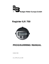
Control Panel
Figure 18: PC200 control panel
Function Keys
Press PROG then use keys 0 to 9 and to enter a PRESET value or configuration value.
Press RATE to display the actual flow rate during batching.
Press TOTAL once to display and reset the actual total.
Press TOTAL twice to display the accumulated total.
Press COUNT to display and reset the number of executed batches.
0
PRINT
Press PRINT to print the currently displayed information.
Press START to begin the batch process or to resume after a HOLD situation.
Press HOLD to interrupt the batch process.
Press RESET after pressing HOLD to completely cancel a batch process.
At the SETUP level, press RESET to reset the totalizers and other values.
Press PROG/ENTER to enter the programming function, to save new PRESET values or other settings and to gain
access to the SETUP level. See “Configuration” on page21.
Press after pressing PROG to enter a decimal value. During configuration, press to select a function or value.
See “Configuration” on page21.
During configuration, press this arrow key to select a function or value. See “Configuration” on page21.
User Manual
Page 17 April 2017 CTL-UM-00483-EN-07

Operator Information and Functions
In general, the PC200 functions at the Operator level. The information displayed and the functional keys available depend on
the SETUP settings and the active function.
A key symbol indicates a particular key or function is locked and not available.
Enter a Batch Quantity
To change the PRESET value:
1. Press PROG. The word "PROGRAM" ashes on the display.
2. Use the numerical keyboard 0-9 and the decimal position to enter the new value.
3. Press ENTER to save the new value or press RESET to cancel the change and keep the PRESET value.
Figure 19: Example display information during programming preset value
Batch Maximum / Minimum
If you try to program a value that is not valid (the batch size is too large or too small), the increase ( ) or decrease ( ) sign
displays. The new value is ignored and the minimum or maximum allowed value is set.
Starting the Batch Process
The batch process can only be started up when "READY" is displayed. The batch process is started up by pressing the START
key. Depending on the SETUP settings, one or two relays will be switched. The arrows at the display indicate if the ACTUAL
value will be counting up or down.
Once the PRESET quantity is reached, the batch outputs will be switched off and the batch process is ended. A next batch can
be started with the same PRESET quantity or a new value can be entered.
The PC200 is equipped with a smart (self learning) overrun correction: at the end of the process, the outputs will be switched
OFF earlier as the PRESET value, taking the overrun quantity of previous batches into account. The result is an accurate batch,
even in slowly varying circumstances. During overrun, a clock will display and "R1 / R2" will be flashing.
Figure 20: Example display information during the process
Industrial Process Controller, Model PC200
Page 18 April 2017CTL-UM-00483-EN-07

Interrupting and Ending the Batch Process
When you press HOLD, the batch process is temporarily interrupted; the actual values are not lost. The word "HOLD" flashes
on the display. From this point, you can press START to resume the batch process.
You can end the batch process entirely at any time by pressing RESET.
OTE:N The actual values are lost and the system returns to steady state. The batch cannot be resumed.
Figure 21: Example display information when interrupted
Additional key functions:
Flow rate indication During batching, the actual flow rate will display after pressing the RATE key. To
return to the main display: press RATE again or wait for 20 seconds.
Display total and accumulated total When the TOTAL key is pressed once, the resettable total will display. After
pressing this key again, accumulated total will display.
The accumulated total cannot be reinitialized. The value will count up to
9,999,999,999. The unit and number of decimals are displayed according to the
configuration settings for preset. To return to the main display: press TOTAL
again or wait for 20 seconds.
Clear total The value for total can be reinitialized. To do so, select TOTAL and press RESET:
the flashing text "PUSH RESET" will display.
To avoid reinitialization at this stage, press a key other than RESET or wait for 20
seconds. If RESET is pressed again, TOTAL will be reset to zero.
Reinitialization of total DOES NOT influence the accumulated total.
OTE:N Total can only be reset if no batch process is active (status: READY).
OTE:N This function might not be available due to configuration settings.
Display batch counter The number of completed batches is displayed after pressing COUNT. To return
to the main display: press COUNT again or wait for 20 seconds.
Clear batch counter The value batch counter can be reinitialized. To do so, select COUNT and press
RESET: the flashing text "PUSH RESET" will display.
To avoid reinitialization at this stage, press a key other than RESET or wait for
20 seconds. If RESET is pressed again, COUNT will be reset to zero.
OTE:N COUNT can only be reset if no batch process is active (status: READY).
OTE:N This function might not be available due to configuration settings.
User Manual
Page 19 April 2017 CTL-UM-00483-EN-07

Operator Alarms
No Flow Alarm
The PC200 offers a no-flow monitoring feature: if the flow meter fails to generate a signal during a certain period of time, the
unit will shut off the control outputs and bring the batch controller in HOLD and alarm mode. A “NO FLOW” alarm message
will display.
To clear the alarm, press RESET once while the batch controller remains in HOLD mode. When in HOLD mode, the batch can
be continued or interrupted. See “Interrupting and Ending the Batch Process” on page19.
Flow Rate Alarm
If during a batch process the actual flow rate is outside the allowed range, a “LO RATE”, or “HI RATE” alarm message will display,
indicating the type of alarm: “LO RATE”, “HI RATE”.
Based on the configuration setting 4.5 Reset Flow Rate Alarm, the following will happen:
• Auto mode: The process is not interrupted, the alarm cannot be cleared and will disappear once the flow rate is within its
limits again.
• Manual mode: Press FLOW RATE followed by RESET to acknowledge the alarm; the alarm will disappear. The alarm will be
cleared automatically in case the batch process is ended.
• Hold mode: The batch process will go on HOLD automatically as soon as the flow rate is outside the allowed range. To clear
the alarm, press RESET once, while the batch controller remains in HOLD mode. When in HOLD mode, the batch can be
continued or cancelled completely. See “Interrupting and Ending the Batch Process” on page19.
Alarm 01-03
If “ALARM” is displayed when no process alarm is present (no flow or flow rate alarm), press the “1” key to display the reason for
the alarm.
See “Troubleshooting” on page32.
Industrial Process Controller, Model PC200
Page 20 April 2017CTL-UM-00483-EN-07
/