Page is loading ...

Model F110
Display /Totalizer
AC_F110_BA_02_1346 (November 2014)
Instruction and operation
manual

Model F110, Display / Totalizer
Page II AC_F110_BA_02_1346 November 2014

User manual
November 2014 AC_F110_BA_02_1346 Page III
CONTENT
1. Safety instructions ................................................................................................................................................................................................................... 1
1.1 Basics ................................................................................................................................................................................................................................ 1
1.2 Safety guidelines and measures ............................................................................................................................................................................ 1
2. Repairs ......................................................................................................................................................................................................................................... 1
3. To the owner ............................................................................................................................................................................................................................. 2
4. Introduction ............................................................................................................................................................................................................................... 3
4.1 System description of the F110 ............................................................................................................................................................................. 3
4.2 Control panel ................................................................................................................................................................................................................ 3
5. Operation.................................................................................................................................................................................................................................... 4
5.1 In general ........................................................................................................................................................................................................................ 4
5.2 Display flow rate / total or flow rate ..................................................................................................................................................................... 4
5.3 Resetting the totalizer ............................................................................................................................................................................................... 4
5.4 Display accumulated total ....................................................................................................................................................................................... 4
5.5 Display of time and date .......................................................................................................................................................................................... 4
5.6 Low battery level ......................................................................................................................................................................................................... 4
6. Configuration / setup ............................................................................................................................................................................................................. 5
6.1 In general ........................................................................................................................................................................................................................ 5
6.2 SETUP level .................................................................................................................................................................................................................... 5
6.3 Scrolling through SETUP .......................................................................................................................................................................................... 6
6.3.1 Selection of functions group and function ........................................................................................................................................ 6
6.3.2 To change or select a value ...................................................................................................................................................................... 6
6.3.3 To return to the operator level ................................................................................................................................................................ 7
6.3.4 Functions overview of the SETUP level ................................................................................................................................................ 7
6.4 Explanations of the SETUP functions ................................................................................................................................................................... 8
6.4.1 Totalizer – 1 ..................................................................................................................................................................................................... 8
6.4.2 Flow rate – 2 ................................................................................................................................................................................................... 9
6.4.3 Display - 3 ..................................................................................................................................................................................................... 10
6.4.4 Power management - 4 ........................................................................................................................................................................... 10
6.4.5 Flow meter - 5 ............................................................................................................................................................................................. 10
6.4.6 Analog output - 6 ...................................................................................................................................................................................... 11
6.4.7 Pulse output - 7 .......................................................................................................................................................................................... 11
6.4.8 Communication (optional) - 8 .............................................................................................................................................................. 12

Model F110, Display / Totalizer
Page IV AC_F110_BA_02_1346 November 2014
6.4.9 Others – 9 ...................................................................................................................................................................................................... 12
7. Installation ............................................................................................................................................................................................................................... 13
7.1 Hints .............................................................................................................................................................................................................................. 13
7.2 Installation / environmental conditions .......................................................................................................................................................... 13
7.3 Housing dimensions ............................................................................................................................................................................................... 14
7.4 Hardware installation ............................................................................................................................................................................................. 14
7.5 Terminal connectors ............................................................................................................................................................................................... 15
7.5.1 Overview ....................................................................................................................................................................................................... 15
7.5.2 Voltage supply flow meter pick up ..................................................................................................................................................... 15
7.5.3 Pulse output ................................................................................................................................................................................................ 16
7.5.4 External power supply 5-30VAC/DC .................................................................................................................................................. 16
7.5.5 Analog output............................................................................................................................................................................................. 16
7.5.6 Inputs ............................................................................................................................................................................................................. 17
7.5.7 Option – communication / printer RS232/RS485.......................................................................................................................... 18
8. Maintenance ........................................................................................................................................................................................................................... 19
8.1 Hints .............................................................................................................................................................................................................................. 19
8.2 Battery lifetime .......................................................................................................................................................................................................... 19
8.3 Maintenance rate ..................................................................................................................................................................................................... 19
9. Appendix A: Technical specifications ........................................................................................................................................................................... 20
10. Appendix B: Troubleshooting ....................................................................................................................................................................................... 21
11. List of actual settings ........................................................................................................................................................................................................ 22
12. Warranty ................................................................................................................................................................................................................................ 23
13. Return of goods for repair / Harmlessness declaration....................................................................................................................................... 24

Safety instructions
November 2014 AC_F110_BA_02_1346 Page 1
1. SAFETY INSTRUCTIONS
1.1 Basics
The manufacturer is not liable for damages that result from improper or not in accordance with the requirements use.
The meters are constructed according to state-of-the-art technology and tested operationally reliable. They have left the
factory in a faultless condition concerning safety regulations.
The mounting, electric installation, taking into operation and maintenance of the meter may only be carried out by suitable
technicians. Furthermore, the operating personnel has to be trained by the operating authority and the instructions of this
manual have to be followed.
Basically, you have to respect the regulations for the opening and repairing of electrical equipment valid in your country.
ELECTROSTATIC DISCHARGE DOES INFLICT IRREPARABLE DAMAGE TO ELECTRONICS! BEFORE
INSTALLING OR OPENING THE UNIT, THE INSTALLER HAS TO DISCHARGE HIMSELF BY TOUCHING
A WELL GROUNDED OBJECT.
1.2 Safety guidelines and measures
• Check mains supply and type plate before installation.
• Check all connections, settings and specifications of the peripheral devices.
• Open the housing only if all leads are free of potential.
• Never touch the electronic components (ESD sensitivity).
• Never expose the system to heavier conditions than allowed according to the housing classification.
2. REPAIRS
If you should send back a flow meter in operation, please take notice of the following points:
- Please enclose a description of the error as well as a precise statement of the measured medium (if necessary a safety
specification sheet).
- The meter has to be in a cleaned condition. Especially with harmful measuring mediums you have to pay attention that
there are no impurities left.
- Please copy and fill in the harmless declaration at the end of this manual and send it back together with the meter to be
repaired.
We reserve the right to repair only cleaned meters. Costs, which result from insufficient cleaning, will be charged to you.

To the owner
Page 2 AC_F110_BA_02_1346 November 2014
3. TO THE OWNER
Thank you for purchasing a MN series flow meter and accessories. Please take a few minutes to read through this manual
before installing and operating your meter. If you have any problems with the meter, refer to the maintenance and
troubleshooting sections of this manual.
This manual contains connection and operating instructions. If you need further assistance, contact us or your local
representative for advice.
This operation manual is divided into two main sections:
• The daily use of the unit is described in chapter "Operation". These instructions are meant for users.
• The following chapters and appendices are exclusively meant for electricians/ technicians. These provide a detailed
description of all software settings and hardware installation guidance.
Three kinds of pictograms appear in this manual:
A "WARNING" INDICATES ACTIONS OR PROCEDURES, WHICH, IF NOT PERFORMED CORRECTLY,
MAY LEAD TO PERSONAL INJURY, A SAFETY HAZARD OR DAMAGE OF THE A130-PPMS OR
CONNECTED INSTRUMENTS.
A "CAUTION" INDICATES ACTIONS OR PROCEDURES, WHICH, IF NOT PERFORMED CORRECTLY,
MAY LEAD TO PERSONAL INJURY OR INCORRECT FUNCTIONING OF THE F110 OR CONNECTED
INSTRUMENTS.
A "NOTE" indicates actions or procedures, which, if not performed correctly, may indirectly affect operation or may lead to an
instrument response, which is not planned.
This operation manual describes the standard unit as well as most of the options available. For additional information, please
contact your supplier.

Introduction
November 2014 AC_F110_BA_02_1346 Page 3
4. INTRODUCTION
4.1 System description of the F110
The display / totalizer F110 is a battery-powered device driven by microprocessors for displaying of the flow rate, total and
accumulated total. For that purpose, one flow meter can be connected to the F110. Two outputs are standardly available:
• Pulse output (open collector): A scaled pulse mirroring the count on the display is generated for use by external
instruments like counters for example.
• The passive analogue output with 10 bits’ resolution has programmable set points according to the flow rate for both
4mA and 20mA.
Furthermore, options are available for full communication RS232/485 (also battery powered) and intrinsically safe.
The F110 is designed to be implemented in many types of applications. For that reason, a SETUP level is available to configure
your display/totalizer best according to your requirements. SETUP includes several important features as K-factors,
measurement units, signal selection, etc. To extend the battery life time, please make use of the power management
functions as described in chapter 6.4.4.
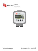
4.2 Control panel
Control panel
PROG / ENTER : This key has no function at operator level. It is used only to configure the unit; please read chapter
"Configuration".
SELECT / : This key is used to SELECT accumulated total, time/date and the main display. The arrow-key is
only used to configure the unit; please read chapter "Configuration".
CLEAR / : Press this key twice to CLEAR the actual value for total. The arrow-key is only used to configure
the unit; please read chapter "Configuration".

Operation
Page 4 AC_F110_BA_02_1346 November 2014
5. OPERATION
5.1 In general
This chapter describes the daily use of the display / totalizer. This instruction is meant for the users/operators.
In general, the display/totalizer will always act at operator level. The information displayed depends on the SETUP settings.
Although the refresh rate of the display might be slow (due to power management functions), each flow meter pulse will be
measured. After pressing a key, the display will be updated very fast for 30 seconds after which it will slow down again.
5.2 Display flow rate / total or flow rate
This is the main display information of the F110. After selecting other information, it will
return to the main display automatically. The actual flow rate is either displayed at the
bottom line or with the 17mm digits at the upper line.
When "-------" are shown, the flow rate value is too high to be displayed. The arrows
indicate the increase/decrease of the flow rate.
5.3 Resetting the totalizer
The value for total can be initialised. To do so, press CLEAR twice. After pressing CLEAR once, the text "PUSH CLEAR" is
displayed while the display information is flashing. To avoid initialisation in that stage, press a different key or wait for 10
seconds. Initialisation of total DOES NOT influence accumulated total.
5.4 Display accumulated total
When the SELECT key is pressed, total and accumulated total are displayed. Accumulated total can never be resetted. The
value will count up to 99,999,999,999. The unit and number of decimals are according to the totalizer.
5.5 Display of time and date
After pressing SELECT twice, the actual time and date is displayed.
5.6 Low battery level
When the battery voltage drops, the battery must be replaced. As soon as "low battery" is
displayed, please order a new battery. The remaining life time after the first moment of
indication is in general several days up to some weeks.

Configuration / setup
November 2014 AC_F110_BA_02_1346 Page 5
6. CONFIGURATION / SETUP
6.1 In general
• Mounting, electrical installation, start-up and maintenance of the instrument may only be carried out by trained
personnel authorized by the operator of the facility. Personnel must read and understand this operating manual before
carrying out its instructions.
• Personnel who are authorized and trained by the operator of the facility may only operate the F110. All instructions in this
manual are to be observed.
• Ensure that the measuring system is correctly wired up according to the wiring diagrams. Only trained personnel may
open the housing.
• Take careful notice of the "Safety rules, instructions and precautionary measures" in the leading chapters of this manual.
This chapter describes the daily use of the F110. These instructions are meant for users / operators.
6.2 SETUP level
Configuration of the F110 is done at SETUP level. SETUP level is reached by pressing the PROG/ENTER key
for 7 seconds; at which time, both arrows will be displayed. In order to return to the operator level,
PROG will have to be pressed for three seconds. Alternatively, if no keys are pressed for 2 minutes, the
unit will exit SETUP automatically. SETUP can be reached at all times while the F110 remains fully
operational.
Press for 7 seconds to enter SETUP.
NOTE: A pass code may be required to enter SETUP. Without this pass code access to SETUP is denied.
Matrix structure SETUP level

Configuration / setup
Page 6 AC_F110_BA_02_1346 November 2014
6.3 Scrolling through SETUP
6.3.1 SELECTION OF FUNCTIONS GROUP AND FUNCTION
SETUP level is divided into several function groups and functions.
Select a function group with
Select a function with
Each function has a unique number, which is displayed below the word "SETUP" at the bottom of the display. The number is a
combination of two figures. The first figure indicates the function group and the second figure the sub function. Additionally,
each function is expressed with a keyword.
After selecting a sub function, the next main function is selected by scrolling through all "active" sub functions (e.g. 1, 11,
12, 13, 14, 1, 2, 3, 31 etc.).
6.3.2 TO CHANGE OR SELECT A VALUE
a) Press briefly; PROGRAM starts flashing
b) Select or enter value with and / or
c) Press, to confirm the value.
To change a value, use to select the digits and to increase that value. To select a setting, both and can be used. If
the new value is invalid, the increase sign or decrease sign will be displayed while you are programming.
When data is altered but ENTER is not pressed, then the alteration can still be cancelled by waiting for 20 seconds or by
pressing ENTER for three seconds: The PROG procedure will be left automatically and the former value reinstated.
NOTE: Alterations will only be set after ENTER has been pressed!

Configuration / setup
November 2014 AC_F110_BA_02_1346 Page 7
6.3.3 TO RETURN TO THE OPERATOR LEVEL
Press for 3 seconds
6.3.4 FUNCTIONS OVERVIEW OF THE SETUP LEVEL
14
Decimals K-factor: 0-6
13
K-factor: 0.000010 - 9,999,999
12
Decimals: 0 - 1 - 2 -3
1
Total
11
Unit: L - m
3
- kg - lb - GAL - USGAL - bbl - no unit
27
Cut-off: 0.1 - 999.9 seconds
26
Calculation: per 1 - 99 pulses
25
Decimals K-factor: 0 – 6
24
K-factor: 0.000010 - 9,999,999
23
Decimals: 0 - 1
22
Time unit: sec - min - hour - day
2
Flow rate
21
Unit: L – m
3
– kg – lb – GAL – ton – bbl – no unit
3
Display
31
Function: total – flow rate
42
Battery mode: operation - shelf
4
Power management
41
LCD update: fast - 1sec - 3sec -15sec - 30sec
52
Maximum frequency: 1 – 9,999 Hz
51
Signal: NPN - NPN_LP - Reed - Reed_LP
5
Flow meter
NAMUR_LP – COIL HI – COIL LO
63
20MA – flow rate: 0.1 – 9,999.9
62
4mA – Flow rate: 0.1 – 9,999.9
6
Analog
61
Output: enable - disable
71
Pulse width: short – long – off
7
Pulse
72
Pulse: X,XXX,XXX quantity
84
Protocol: Modbus – off
83
Mode: ASCII – RTU
82
Address: 0 – 250
8
Communication
81
Speed: 1200 – 2400 – 4800 - 9600
97
Tag number: 0000000 – 9999
96
Date
95
Time
94
Password: 000 – 9999
93
Serial No.
92
Software version
9
Others
91
Type/model

Configuration / setup
Page 8 AC_F110_BA_02_1346 November 2014
6.4 Explanations of the SETUP functions
6.4.1 TOTALIZER – 1
Measurement unit - 11:
SETUP - 11 determines the measurement unit for total and accumulated total. The following units can be selected:
L - m3 - kg - lb - GAL - USGAL - bbl - _ (no unit).
Alterations of the measurement unit will have consequences for operator and SETUP level values. Please note that the K-factor
has to be adapted as well.
Number of decimals displayed - 12:
The decimal point determines for total and accumulated total the number of digits following the decimal point. The following
can be selected:
0000 - 111.1 - 22.22 - 3.333
K-Factor - 13:
With the K-factor, the flow meter pulse signals are converted to a quantity. The K-factor is determined on the basis of the
measurement unit and the number of pulses generated per unit by the flow meter. Enter the number of pulses generated by
the flow meter per selected measurement unit (per cubic meter e.g.). The more accurate the K-factor, the more accurate the
functioning of the system will be.
Number of decimals displayed for K-Factor - 14:
This function determines the number of decimals for the K-factor (see 13). The following can be selected:
0 - 1 - 2 - 3 - 4 - 5 – 6
Please note that this function influences the accuracy of the K-factor indirectly. This setting has NO influence on the displayed
number of digits for total (SETUP 12)!
Example 1: Calculating the K-factor.
Let us assume that the flow meter generates 2.4813 pulses per litre and the selected unit is "cubic metres / m
3
". A cubic metre
consists of 1000 parts of one litre which implies 2,481.3 pulses per m
3
. So, the K-factor is 2,481.3. Enter for SETUP - 13:
"2481300" and for SETUP - 14 - decimals K-factor "3".
Example 2: Calculating the K-factor.
Let us assume that the flow meter generates 6.5231 pulses per gallon and the selected measurement unit is gallons. So, the K-
Factor is 6.5231. Enter for SETUP - 13: "6523100" and for SETUP - 14 decimals K-factor "6".

Configuration / setup
November 2014 AC_F110_BA_02_1346 Page 9
6.4.2 FLOW RATE – 2
The settings for total and flow rate are entirely separated. In this way, different measurement units can be used like cubic
meters for total and liters for flow rate. Please notice that all these settings influence the analog output as well.
Measurement unit - 21:
SETUP - 21 determines the measurement unit for flow rate. The following units can be selected:
L - m
3
- kg - ton - GAL - bbl - lb - _ (no unit).
NOTE: Alterations of the measurement unit will have consequences for operator and SETUP level values. The K-factor
has to be adapted as well.
Time unit - 22:
The actual flow rate can be calculated per second (SEC), minute (MIN), hour (HR) and day (DAY).
Number of decimals displayed - 23:
The decimal point determines for flow rate the number of digits following the decimal point. The following can be selected:
00000 - 1111.1
K-factor - 24:
With the K-factor, the pulse signals of the flow meter are converted to a quantity. The K-factor is determined on the basis of
the measurement unit and the number of pulses generated per unit by the flow meter. Enter here the number of pulses
generated by the flow meter per selected measurement unit (e.g. per litre). The more accurate the K-factor, the more accurate
the functioning of the system will be. For examples, see SETUP 13.
Number of decimals displayed, K-factor - 25:
This function determines the number of decimals for the K-factor (see setup 24). The following can be selected:
0 - 1 - 2 - 3 - 4 - 5 - 6
Please note that this SETUP influences the accuracy of the K-factor indirectly. This setting has NO influence on the displayed
number of digits for "flow rate" (SETUP 23)!
Calculation - 26:
The flow rate is calculated by measuring the time between pulses. As several types of flow meters have an unequal pulse train,
it is advised to calculate the flow rate over several pulses, for example 10 pulses; the maximum value is 99 pulses.
NOTE: The calculation time for very low frequencies (0.1-5Hz) is influenced by this setting as well; so do not program too many pulses!
When the frequency is above 3kHz during normal conditions, it is advised to calculate more than 50 pulses.
Cut-off time - 27:
With this setting, you determine when a flow rate is zero; when during this time less than XX-pulses (see setup 26) are
generated, the flow rate will be displayed as zero.

Configuration / setup
Page 10 AC_F110_BA_02_1346 November 2014
6.4.3 DISPLAY - 3
Function - 31
The large 17 mm digits can be set to display total or flow rate digits at operator level. When total is selected, both total and
flow rate are displayed simultaneously. When flow rate is selected, total will be displayed after pressing select.
6.4.4 POWER MANAGEMENT - 4
As the F110 is normally battery powered, the user will have the concern of reliable measurement over a long period of time.
The F110 has several smart power management functions to extend the battery life time significantly. Two of these functions
can be set:
LCD refresh - 41:
The calculation of the display information influences the power consumption significantly. When the application does not
require a fast display update, we advise you to select a slow refresh rate.
NOTE: No information will be lost; every pulse will be counted and the output signals are not influenced.
The following can be selected:
Fast - 1 sec - 3 sec - 15 sec - 30 sec.
Example: battery life time with a coil pick-up and FAST update: About 3 years. Battery life time with a coil pick-up and 1 sec
update: About 8 years.
Please note that after a button has been pressed by the operator, the display refresh rate will be FAST during the initial 30
seconds.
Battery mode - 42:
The unit has two modes: operational or shelf. When shelf is selected, you can store the unit for several years; it will not count
pulses, the display is switched off but all settings are stored. In this mode, power consumption is extremely low. Normally, the
mode will be operational.
6.4.5 FLOW METER - 5
Signal - 51:
The F110 is able to handle several types of signals. The type of flow meter pickup / signal is selected in software with SETUP
51.
Type of signal
Explanation
Resistance
Power consumption
Remark
NPN
Standard NPN input
100K pull-up
Relative high
(open collector)
NPN – LP
NPN with low pass filter
100K pull-up
Relative high
(open collector) less
sensitive
REED
Reed-switch input
1M pull-up low
REED – LP
Reed-switch with low
pass filter
1M pull-up low
Less sensitive
PNP
Standard PNP input
100K pull-down
Relative high
PNP – LP
PNP input with low pass
filter
100K pull-down
Relative high
Less sensitive
NAMUR
Standard Namur input
1K pull-down
High
External power required
NAMUR – LP
Namur with low pass
filter
1K pull-down
High
Ext. power required; less
sensitive
COIL HI
High sensitive coil input
-
Very low
Sensitive for signal and
disturbance
COIL LO
Low sensitive coil input
-
Very low
Normal sensitivity
Maximum frequency - 52:
Enter here the maximum frequency the flow meter might generate. It is advised to enter a little higher frequency than will
ever be generated.

Configuration / setup
November 2014 AC_F110_BA_02_1346 Page 11
6.4.6 ANALOG OUTPUT - 6
A passive linear 4-20mA output signal is generated according to the flow rate with a 10 bit resolution. The settings for flow
rate (SETUP - 2) influences the analogue output directly. When the analogue output is not used, please make sure that setting
61 is disabled, else the battery lifetime will be decreased significantly! The relationship between rate and analogue output is
set with following functions:
Enable / disable - 61:
As the D/A converter has a relatively high power consumption, it is strongly advised to power the unit externally. When the
analogue output will not be used, select "disable" to switch-off the converter.
Minimum flow - 62:
Enter here the flow rate which the output should generate a 4mA signal (mostly at rate "zero"). The number of decimals
displayed is according to setup 24. The time and measuring units (L/min e.g.) are according setup 21 and 22 but cannot be
displayed.
Maximum flow - 63:
Enter here the flow rate which the output should generate a 20mA (mostly at maximum possible rate). The number of
decimals displayed is according to setup 24. The time and measuring units (L/min e.g.) are according setup 21 and 22 but
cannot be displayed.
6.4.7 PULSE OUTPUT - 7
One open collector output is available to generate a pulse per quantity. This frequency output is programmable and has a
maximum frequency of 20Hz.
Pulse width - 71:
When the pulse is used to drive an electromechanical counter, a long pulse - 100msec - will be required. Consequently, the
maximum output frequency is 5Hz. For electronic counters a frequency of max. 20Hz. is offered with a short pulse of 25msec.
NOTE: When the frequency goes out of range (when the flow rate increases for example) an internal buffer will be used to "store the
pulses": As soon as the flow rate goes down, the buffer will be "emptied". It might be that pulses will be missed due to a buffer
overflow, so it is advised to program setup 71 within its range. It is advised to select "OFF" when the pulse output is not used.
Pulses per – 72:
According to the settings for total, a pulse will be generated every X quantity. Enter here this quantity while taking the
decimal position and measuring unit into account.

Configuration / setup
Page 12 AC_F110_BA_02_1346 November 2014
6.4.8 COMMUNICATION (OPTIONAL) - 8
Functions as described below deal with hardware that is not part of the standard delivery. Programming of these functions
does not have any effect if this hardware has not been installed.
Baud Rate (optional) - 81:
For external control, following communication speeds can be selected: 1200 - 2400 - 4800 - 9600 baud
Bus address (optional) - 82:
For RS485 communication, a unique identity can be attributed to every F110. This address can vary from 1-250 (consult the
description in the protocol).
ASCII / RTU (optional) - 83:
The Modbus communication protocol is executed according ASCII or RTU mode.
Protocol (optional) - 84:
Select here the type of communication protocol to be used.
6.4.9 OTHERS – 9
Type of model - 91:
Serial number - 93:
Version software - 92:
For support and maintenance, it is important to have information about the characteristics of the display/totaliser. Your
supplier will ask for this information in case of a serious breakdown or a desired extension of the system.
Password - 94:
All SETUP-values can be password protected. This protection is disabled with value 0000 (zero). Up to and including 4 digits
can be programmed, e.g. 1234.
Time - 95:
The actual time is available for the operator and communication purposes. The time has to be inserted in accordance with the
24 hours pattern; HH:MM:SS (hours:minutes:seconds).
Date - 96:
The actual date is available for the operator and communication purposes. The date has to be inserted in accordance with this
pattern: YY-MM-DD (year.month.day).
Tag number - 97:
For identification of the unit and communication purposes, a unique tag number of maximum 7 digits can be entered.

Installation
November 2014 AC_F110_BA_02_1346 Page 13
7. INSTALLATION
7.1 Hints
• MOUNTING, ELECTRICAL INSTALLATION, START-UP AND MAINTENANCE OF THIS INSTRUMENT MAY ONLY BE CARRIED
OUT BY TRAINED PERSONNEL AUTHORIZED BY THE OPERATOR OF THE FACILITY. PERSONNEL MUST READ AND
UNDERSTAND THIS OPERATING MANUAL BEFORE CARRYING OUT ITS INSTRUCTIONS.
• PERSONNEL WHO ARE AUTHORIZED AND TRAINED BY THE OPERATOR OF THE FACILITY MAY ONLY OPERATE THE
F110. ALL INSTRUCTIONS IN THIS MANUAL ARE TO BE OBSERVED.
• ENSURE THAT THE MEASURING SYSTEM IS CORRECTLY WIRED UP ACCORDING TO THE WIRING DIAGRAMS.
PROTECTION AGAINST ACCIDENTAL CONTACT IS NO LONGER ASSURED WHEN THE HOUSING COVER IS REMOVED OR
THE PANEL CABINET HAS BEEN OPENED (DANGER FROM ELECTRICAL SHOCK). TRAINED PERSONNEL MAY ONLY OPEN
THE HOUSING.
• TAKE CAREFUL NOTICE OF THE "SAFETY RULES, INSTRUCTIONS AND PRECAUTIONARY MEASURES" AT THE FRONT OF
THIS MANUAL.
7.2 Installation / environmental conditions
Take the relevant IP classification of the casing into account (see
manufacturer’s plate). Even an IP67 (NEMA 4X) casing should NEVER be
exposed to strongly varying (weather) conditions.
When panel mounted, the unit is IP65 (NEMA 4)!
When used in very cold surroundings or varying climatic conditions, take
the necessary precautions against moisture by placing a dry sachet of
silica gel, for example, inside the instrument case.
Mount the F110 on a solid structure to avoid vibrations.

Installation
Page 14 AC_F110_BA_02_1346 November 2014
7.3 Housing dimensions
Standard IP65 (NEMA 4) ABS housing
7.4 Hardware installation
ELECTROSTATIC DISCHARGE DOES INFLICT IRREPARABLE DAMAGE TO ELECTRONICS! BEFORE
INSTALLING OR OPENING THE UNIT, THE INSTALLER HAS TO DISCHARGE HIMSELF BY TOUCHING
A WELL GROUNDED OBJECT.
THIS UNIT MUST BE INSTALLED IN ACCORDANCE WITH THE EMC GUIDELINES
(ELECTROMAGNETIC COMPATIBILITY).
DO GROUND THE ALUMINIUM CASING PROPERLY (OPTION HA / HU) AS INDICATED, IF THE F110
HAS BEEN SUPPLIED WITH THE 115-230 VAC POWER SUPPLY OPTION.
THE GREEN / YELLOW WIRE BETWEEN THE BACK CASING AND REMOVABLE TERMINAL BLOCK
MUST NEVER BE REMOVED.
Grounding Aluminium enclosure with option PM 115-230V AC
Front view
panel cut-out
bottom view
Side view
(panel mount)

Installation
November 2014 AC_F110_BA_02_1346 Page 15
7.5 Terminal connectors
7.5.1 OVERVIEW
For installation, pay special attention to:
• SEPARATED CABLE GLANDS WITH EFFECTIVE IP67 SEALS FOR ALL WIRES.
• NOT USED CABLE ENTRIES: DO PLACE CLOSED IP67 PLUGS.
• A RELIABLE GROUNDING OF THE SEVERAL COMPONENTS, ELECTRONICS AND - IF BE APPLICABLE - METAL CASING.
• AN EFFECTIVE SCREENED CABLE FOR SIGNAL WIRING AND GROUNDING OF THE SCREENING IN TERMINAL 9 (GND). SEE
7.5.6
7.5.2 VOLTAGE SUPPLY FLOW METER PICK UP
Battery powered and loop powered applications:
A supply voltage of 3.2 Volt DC is available for the signal output of the flow meter. This voltage may not be used to power the
flow meters electronics, converters etc. as it is not a power output! All energy used by the flow meters pick-up influences the
battery lifetime directly; it is strongly advised to use a "zero power" pickup as a coil or reed-switch. It is possible to use a NPN
or PNP output signal, but the battery life time will be reduced.
Externally powered applications 5-30 VAC/DC:
When the F110 is powered with 5-30VAC/DC supply, it is possible to power the flow meters electronics with 3.2 Volt DC (max.
50mA). The type of pick-up does not influence the battery life time as long as the external power supply is available.
NAMUR:
For a NAMUR pick-up, an external power supply of 8.2-30VAC/DC is required. The voltage supply to the flow meter should be
according DIN19 234 (8.2VDC) when NAMUR-input is selected (see setup 51).
Pulse-
output
ext. power-
supply
5
-
30 VAC/DC
Analogue
Output
Sensor signal input

Installation
Page 16 AC_F110_BA_02_1346 November 2014
max.
50VDC
300mA
max.
50VDC
300mA
pull-up resistor
(redundancy)
pulse
Counter device
7.5.3 PULSE OUTPUT
(connectors 4-5, SETUP 71)
An open collector output generates a pulse of 100 msec. (setting long) or 25msec. (setting short) according to a certain
quantity. This output can be used for driving an external counter relay e.g. For power-consumption reasons, it is advised to
select "OFF" when the output will not be used.
7.5.4 EXTERNAL POWER SUPPLY 5-30VAC/DC
(connectors 6-7)
5-30 volt AC/DC: connect an external power-supply to these terminals. For a DC supply connect the + to terminal 6 and the -
to terminal 7.
7.5.5 ANALOG OUTPUT
A 4-20mA-current-sink proportional to the flow rate is available. A DC
power supply should be connected to the F110 where the current is
regulated by the F110. The analogue output signal influences the
battery lifetime significantly; therefore, it is strongly advised to
connect a separate power line to connector 6. Do NOT use the same
wire as the analogue value will be incorrect! When the analogue-
output is not used, please make sure that setup 61 is disabled.
/