Page is loading ...

BadgerMeter,Inc.
®
Installation &
Operation Manual
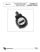
Model ER-9
Digital Resettable Totalizer and
Digital Rate of Flow Indicator
with Pulse Output
ER9-IOM-01
12-01

The ER-9 is an external or battery powered indicator that displays rate
of flow and total flow. It also has a scalable pulse output. It has
independent programmable scale factors for rate and totalization,
allowing you to program these displayed values in different but
meaningful engineering units, such as gallons per minute and total
gallons.
The supertwist LCD display with 8 digits for total, and 4 digits plus
legend for rate, provides easy viewing at a glance. For conditions
where ambient light is poor, the display can be backlit by connecting
an external DC (10-28 VDC) power supply. A single unit can accept
NPN or dry contact inputs for low or high speed applications.
Count Input (Terminal 2):
Type: NPN Signal, or Contact Closure
Count Speed: NPN-280Hz max., Contact-95Hz max.
Logic: Low < 1.0 VDC, High > 2.0 VDC,
Minimum Pulse Width: NPN-1.78 microseconds, Contact-5ms
Maximum Input: 28VDC
Impedance: 1 Mohm to battery
Front Panel Enable Input (Terminal 5)
Type: NPN Signal, or Contact Closure; level sensitive
Maximum Input: 28 VDC
Remote Reset Input (Terminal 4)
Type: NPN Signal, or Contact Closure; edge sensitive
Frequency Response: 30 Hz (50% duty cycle)
Maximum input: 28 VDC
Pulse Output (Terminals 6 & 7)
Type: Isolated photo MOS relay
Load rating: 0.1 amp @ 30VAC/VDC
Transition time: <5ms
2
Scope of this manual
This manual contains information concerning the installation, operation
and maintenance of the Badger ER-9 indicator. To ensure proper
performance, the instructions given in this manual should be thoroughly
understood. Retain the manual in a readily accessible location for future
reference.
Installation, wiring and programming of the ER-9 is fairly simple and
straight forward. This manual is designed so as to provide you with a step
by step guide for this purpose.
Examples are provided only to facilitate programming. Your specific
application will most likely require a different set of numbers for proper
programming.
The troubleshooting section attempts to illustrate the most common
problems that can be encountered, their most likely cause and the
recommended solution. If a problem persists, please contact our techni-
cal support group at:
Badger Meter, Inc.
1-414-355-0400
Specifications
Power Source:
Type: Dual 3V Lithium batteries
(Battery P/N 62872-001)
Expected Life: 5 years (with external DC source)
Low Power Indicator: "Low Bat" flashes on display
approx. 2 weeks prior to end of battery life
Display:
Type: Supertwist LCD for use with or without backlighting
Number: 8 digits count value, 4 digits (plus dead zero) for rate
value
Height: 12mm (.472")
Backlighting: Green Illumination over viewable area with a 10 to 28
VDC supply (Terminal 8)
Physical:
Dimensions: 36mm x 72mm, 38mm deep
1.417in x 2.835in, 1.496 in. deep
Mounting: Panel Mount (mounting bracket supplied)
33mm x 68mm (+ 0.3mm) panel cutout
1.299in x 2.677in, (+ 0.012in) panel cutout
Connections: Screw terminals
Weight: Approximately 13 ounces
Powered by two replaceable 3V Lithium batteries, this unique design
allows for a new battery to be installed before removing the old one,
thereby retaining count total and program data. A low battery indicator
appears on the screen to provide a warning a couple of weeks before
the end of battery life.
The unit will operate in battery mode for at least six months. To extend
battery life to five years the unit must be connected to an external DC
power source.
Setup is quick and easy as the two front panel keys are used to scroll
through and preset values in all program mode choices.
This Product Contains Lithium Batteries.
Read This Manual Before Attempting Any Installation,
Wiring Or Operation.
General Information

EPT1 Black (1) Red (2)
FT1 (1/2" OP) Black (1) Black (2)
FT1E Black (1) Green (2)
FT2 White (1) White (2)
FT420 Black (1) White (2)
MSE1 Black (1) Red (2)
MSE5 Black (1) Red (2)
PFT1E Brown (1) Orange (2)
PFT2 White (1) White (2)
PFT2E Black (1) Green (2)
PFT3E Black (1) Green (2)
PFT3W Black (1) Red (2)
PFT420 Black (1) White (2)
PFT420/2 Black (1) White (2)
PFT4E Brown (1) Orange (2)
PM5 Black (1) Red (2)
3
Installation
Battery Installation
The ER-9 is shipped with two batteries, which are not installed.
Remove the battery cover by pushing inward and down. Install the
batteries in the two slots. The two batteries are capable of sustaining
the pulse output for 6 months at 50% duty cycle.To extend battery life
to 5 years, utilize an external DC supply for powering the pulse output.
Once the batteries are in place the unit will go into a self test mode, and
all the segments on the LCD display will be illuminated. The self test
mode is exited by depressing the key, which will then display
the model number (9). Depress again to ready the unit for
operation.
1. DC Common
2. Count Input - NPN Signal 280 Hz max. or Dry Contact 95 Hz
max.
3. Not used.
4. Remote Reset - Resets count value when switched to common.
5. Front Panel Program Enable - allows access to program mode
when connected to common.
6. Solid State Relay- Pulse output (+).
7. Solid State Relay- Pulse output ( - )
8. DC Supply Input - 10 to 28 VDC for backlighting and/or powering
the output.
Transmitter Connections
Panel Installation
Place the unit in the panel through a 33mm x 68mm cutout. Slide the
included gasket over the rear of the unit, then slide the panel mount
bracket into place so that the 4 tabs catch in the grooves on the top and
the bottom of the unit (the bracket should be oriented so that the tabs
are on the side nearest the panel). Use the provided panel mount
screws to tighten the bracket until there is a secure seal against the
gasket. Do not over tighten.
TRANSMITTER CONNECTIONS
For connecting to Badger Meter transmitters, refer to the Technical
Brief for your specific transmitter, and the chart to the right. "Connec-
tions" refers to the wires on the transmitter. The numbers in parenthe-
sis refer to the terminal numbers on the ER-9. Connect the wire coming
from the transmitter to the corresponding terminal number on the ER-
9.
To connect a generic reed switch to the ER-9, connect one of the
wires to terminal 1 on the ER-9.
Connect the remaining wire to terminal 2.
To connect a generic NPN transmitter to the ER-9, connect the
emitter to terminal 1 on the ER-9. Connect the collector to terminal 2.
Wiring Instructions
R
R

R
R
R
R
R
R
R
R
• Step 3-On program modes 1 & 4 use the and keys in
combination to choose individual digits and change their value.
Note that on program modes #1, #4 & #6 you can advance to the next
program mode only if a digit is not flashing. Use the key until
the display is not flashing.
After all programming is complete, remove the connection between
terminals 1 and 5 in order to insure that the unit is not reprogrammed
by mistake.
Note: Programming can be done only if terminals 1 and 5 are
connected (together)
• Step 1- Toggle the key until the desired program mode
appears on the screen (1 through 7).
• Step 2- Once the desired program is selected, pressing the key
will either cause the left most digit of that value to flash (scale factors
modes 1 & 4), or it will change the parameters for the other program-
ming modes (decimal point position and totalizer reset)
4
By pressing the DOWN key during normal operation, the ER-9 will alternatively display the Flow Total or the Flow Rate. The
Letter R on the left indicates that the Flow Rate is being displayed.
Total Display: Indicates the present
count value, which is equal to the num-
ber of pulses received (since the last
reset) multiplied by the Totalizer Scaler
Value in Program mode #1.
Rate Display: Indicates the rate value,
which is equal to the input frequency
multiplied by the Rate Prescale Value in
Program Mode #3. (If no pulses are
received for 2 seconds, the rate value
goes to zero.)
When the program input is active (see wiring) this key
is used to select a menu item for editing.
or
Reset Key:
If the total value is being displayed, depressing this
key will cause the value to be reset to 0 as long as
program mode #6 is preset accordingly.
Down Key: Toggles the unit between the total and rate display. When the program input is active this key
is used to scroll through the menu items. After a menu item has been chosen for editing, the down key is
used to set the value for the currently selected (flashing) digit.
Operation
Programming
5. oFF
Mode #5: Rate Decimal Point: Sets the
decimal point on the Rate of Flow display
from no decimal (off) to 0.000. You can also
program the display to have a dead zero (-
---0), for a 5 digit display with the least
significant digit always being "0".
1. 99.9999
Mode #6: Pulse output scale factor:
Multiplies the input pulses by a number -
from 0.0001 to 0.9999 - and sends them to
output terminals 6 & 7.
7. on
6. 0.9999
Mode #1: Totalizer Scaler:
Multiplies the input pulses by
this number (Programmable
from 0.0001 to 99.9999) and
displays the results as the to-
talizer value.
2. oFF
Mode #2: Totalizer Decimal
Point: Sets the decimal point
on the totalizer display from no
decimal (off) to 0.00000.
3. 1.000
4. 9999
Mode #4: Rate Scale Factor:
Multiplies the input pulses by
this number, which can be pro-
grammed in conjunction with
the Rate Decimal Point for a
number from 0.001 to 9999.
Mode #3: Rate Scale Factor
Decimal Point: Sets the deci-
mal in the Rate Scale Factor
number, from no decimal to
0.000.
Mode #7: Front Panel Reset Enable: When
programmed "on" the key will reset
the totalizer to zero when depressed. When
programmed "off" the totalizer can only be
reset through the remote reset input (see
wiring).
2345
R
R
R
34675890
R
R
R
R

that has a pulse output of 126.7 pulses per gallon. You wish to read
rate of flow in gallons per minute.
60 seconds /126.7 pulses per gallon X 1
= 60/126.7 = 0.473(rate scale factor)
Step #1: Set the rate scale factor decimal point to X.XXX (Program
mode # 3)
Step #2: Set the rate scale factor to 0.473 (Program mode # 4)
Step #3: Since we are reading in whole gallons, set program mode #
5 (Rate Decimal Point) to “off”.
PULSE OUTPUT PROGRAMMING
The Pulse Output can be programmed for any engineering unit of
measure. A Pulse Output Scale Factor must be calculated and
programmed (mode # 6) using the same formula and procedure as
described under the Totalizer Scale Factor. (Program mode #4).
When not using the pulse output, program to 0.0000 to conserve
power.
TOTALIZER PROGRAMMING
Totalizer values can be expressed in any engineering unit of measure
such as gallons, quarts, liters, etc. For each unit a unique scale factor
must be programmed.
To determine the Totalizer Scale Factor (Program Mode #1), use the
following formula:
Totalizer Scale Factor =
1/(Transmitter pulses per unit X Decimal Factor)
where:
Transmitter Pulses per Unit is the number from the chart at the right,
or the Tech Brief for your particular transmitter/meter combination.
The chart is expressed in gallons and liters. If you wish to read in other
units, use the appropriate conversion factor.
Decimal Factor determines the resolution of the reading. If you wish
to read to the nearest 1/10 unit, the Decimal Factor would be 0.1.
Example: You have a model 35 RCDL meter with a PFT2 transmitter
that has a pulse output of 126.7 pulses per gallon. You wish to read
the totalizer to the nearest tenth gallon.
1/(126.7 X 0.1) = 0.0789 (scale factor)
Step #1: Set the totalizer Decimal Point Factor to “0.0” (one decimal
place) (Program Mode #2).
Step #2: Set The Totalizer Scale Factor to 0.0789.(Program Mode #1)
RATE OF FLOW PROGRAMMING
Rate of flow can be expressed in any engineering unit of measure for
any time base such as gallons/minute, liters/second, barrels/hour, etc.
To determine the Rate Scale Factor (Program Mode #4), use the
following formula:
Rate Scale Factor =
Seconds / Transmitter Pulses per Unit X Decimal Factor
where:
Seconds is the number of seconds in the rate time unit. If you wish to
read flow in units per minute, seconds would equal 60. If you wish to
read flow in units per hour, seconds would equal 3600.
Decimal Factor determines the resolution of the reading. If you wish
to read to the nearest 1/10 unit, the Decimal Factor would be 0.1.
Transmitter Pulses per Unit is the number from the chart to the right
or the Tech Brief (ITB) for your particular transmitter/meter combina-
tion. The chart is expressed in gallons and liters. If you wish to read
in other units, use the appropriate conversion factor.
Before you program the Rate Scale Factor, you must set the Rate
Decimal Point position (Program Mode #3). This decimal point will
correspond to the decimal in the Rate Scale Factor number.
Example: You have a model 35 RCDL meter with a PFT2 transmitter
ER9 Programming Calculations
5
*If using a PFT3E transmitter, multiply number by 4.
Transmitter Pulses per Unit chart
FT1 FT2
PFT2 PFT3W FT420
PFT2E FT1E PFT420
Size
(Inches) Meter Model Gallons Liters Gallons Liters
5/8 SC-ER 160.0 42.3 320.0 84.5
3/4 SC-ER 132.9 35.1 265.8 70.2
1 SC-ER 43.4 11.5 86.9 23.0
1 1/2 SC-ER 19.1 5.0 38.2 10.1
2 SC-ER 10.0 2.6 20.1 5.3
1/2 OP 223.0 58.9 445.9 117.8
1/2 OP(FT1 only) 111.5 29.4 ––
1 OP 76.6 20.2 153.3 40.5
2 OP 20.6 5.4 41.1 10.9
2 TURBO * 8.7 * 2.3 17.4 4.6
3 TURBO * 6.2 * 1.6 12.4 3.3
4 TURBO * 1.3 * 0.3 2.6 0.7
6 TURBO * 0.5 * 0.1 1.1 0.3
5/8 15 IND RCDL 350.8 92.7 701.6 185.3
5/8 25 IND RCDL 198.4 52.4 396.8 104.8
3/4 35 IND RCDL 126.7 33.5 253.3 66.9
1 40 IND RCDL 89.8 23.7 179.6 47.4
1 1/2 70 IND RCDL 46.8 12.4 93.6 24.7
2 120 IND RCDL 23.8 6.3 47.6 12.6
2 170 IND RCDL 14.6 3.9 29.1 7.7

PROBLEM POSSIBLE CAUSES REMEDIES
Screen is blank 1. Battery is dead. 1. Replace battery.
Will not count in totalizer mode 1. Improperly programmed. 1. Check programming.
2. Broken or defective wiring. 2. Check wiring.
3. Improperly connected. 3. Check connections.
4. Transmitter defective. 4. Repair or replace transmitter.
Will not indicate rate of flow 1. Improperly programmed. 1. Check programming.
2. Improperly connected. 2. Check connections.
3. Transmitter defective. 3. Repair or replace transmitter.
Cannot program 1. Program enable jumper is not 1. Install jumper.
installed or installed improperly.
Cannot reset from front panel 1. Reset enable is not 1. Reprogram mode #6 to ON.
programmed.
Erroneous readings 1. Improperly programmed. 1. Check programming.
2. Defective transmitter. 2. Repair or replace transmitter.
No Pulse Output 1. Defective output Transistor 1. Replace ER-9
2. Improper wiring 2. Check connections
Field calibration consists of determining the exact transmitter pulse
output per unit of measure for your particular meter/transmitter com-
bination and then using this value as the transmitter pulse output value
when calculating the counter and time base values on page 4.
The procedure is as follows:
1. Set the totalizer scale factor to "1".
2. Set the totalizer Decimal Point to "off".
3. Reset the counter to “zero”.
4. Run fluid into a weigh tank or calibrated vessel.
5. Determine number of pulses per gallon by dividing indicator
reading by number of gallons of fluid in the vessel. Use this value
for your calculations.
Troubleshooting
Field Calibration
Example:
You programmed the indicator for calibration and connected the outlet
of a 1" OP meter to a calibrated vessel. You opened the valve and
allowed fluid to flow into the vessel. You determined that there was
22.35 gallons of fluid in the vessel. The reading on the indicator is 1720.
1720 / 22.35 = 76.95
The transmitter output is 76.95 pulses per gallon. Use 76.95 when
calculating the Totalizer Scale Factor on page 5.
6
For further assistance, call our Technical Support Staff at 414-355-0400, Extension 637.

If replacement of your sensor pickup on your meter is required, please
follow the following steps:
TURBO METER
1. Remove the front cover on the ER-8 or ER-9 unit and disconnect
all wiring.
2. Remove meter head bolts and lift meter head assembly from
housing.
3. Remove retaining ring which retains the accessory unit to the head.
4. Loosen the side seal screw on the accessory adapter, twist 90° and
pull entire assembly unit from the meter head.
5. Twist drop pipe in counterclockwise direction to remove it and the
ER-8/9 unit from the adapter assembly.
6. Obtain new adapter assembly and reassemble to drop pipe and
ER-8/9 unit.
7. Reverse the balance of the above steps.
DISC METER
1. Remove the front cover on the ER-8 or ER-9 unit and disconnect
sensor wiring.
2. Loosen the side seal screw on the assembly adapter, twist 90° and
lift entire accessory unit off bare meter.
Meter Mount Surfacing
3. Pull the reed switch pickup assembly and pad from adapter.
4. Replace pickup and pad in adapter, feeding wires up through the
drop pipe.
5. Reposition entire assembly on meter.
6. Rewire sensor to ER-8/9 unit.
OP METER
1. Remove the front cover on the ER-8 or ER-9 unit and disconnect
sensor wiring.
2. Remove the back plate on the meter to expose the pickup assem-
bly.
3. Remove the reed switch pickup assembly and replace.
4. Feed wires up through the drop pipe.
5. Reassemble the back plate in position.
6. Rewire sensor wires to ER-8/9 unit.
7

®
Due to continuous research, product improvements and enhancements,
Badger Meter reserves the right to change product or system specifications
without notice, except to the extent an outstanding bid obligation exists.
Copyright © Badger Meter, Inc. 2001. All rights reserved, all data subject to change without notice.
Please see our website at
www.badgermeter.com
for specific contacts.
BadgerMeter,Inc.
P.O. Box 245036, Milwaukee, WI 53224-9536
(800) 876-3837 / Fax: (888) 371-5982
www.badgermeter.com
/