Page is loading ...

sec.3m
−−−−
1
2 VOICE - Technical Manual
SECTION 3M
PUSH BUTTON PANEL
Download from www.urmet.com Technical Manuals area.
SECTION CONTENTS
ALPHA PUSH BUTTON PANEL 2
FEATURES .......................................................................................2
AUDIO VIDEO DOOR UNIT REF. 1083/48, AUDIO DOOR UNIT REF.
1083/38 (1 MODULE) AND DOOR UNIT WITH CCTV REF. 1083/39 ... 2
Structure .......................................................................................2
Description of terminals ................................................................3
Description of the wires for connecting device to surveillance
cameras (feature available only on door unit ref. 1083/39) ..........3
Technical specications ...............................................................3
Default conguration ....................................................................3
Operation ......................................................................................3
ILA AND VOICE SYNTHESIS MODULE REF. 1168/48 ....................4
Structure .......................................................................................4
Installation .................................................................................... 4
Speech synthesis language selection ..........................................4
Speech synthesis volume adjustment ..........................................4
Technical specications ..............................................................4
BUILDING NUMBER MODULE REF. 1168/50 .................................5
Installation .................................................................................... 5
BLIND MODULE SCH. 1168/59 .......................................................5
4-BUTTON MODULE SCH. 1168/4 .................................................. 5
8-BUTTON MODULE SCH. 1168/8 .................................................. 5
FLUSH-MOUNTED PANEL ACCESSORIES .................................... 6
Flush-mounting boxes ..................................................................6
Joining ush-mounting boxes ......................................................6
Module holder frames...................................................................6
Wall cover frame ...........................................................................6
Wall frame cover installation .........................................................7
WALL-MOUNTED PANEL ACCESSORIES ......................................7
Casings with frame .......................................................................7
Casing and frame joiner ...............................................................7
PANEL ACCESSORY IN COMMON TO BOTH VERSIONS .............7
Rain hood cover ...........................................................................7
ALPHA PUSH BUTTON PANEL INSTALLATION ............................. 8
Flush-mounted version .................................................................8
Wall-mounted version.................................................................10
COMPLEMENTARY PRODUCTS LIST ..........................................12
OVERALL DIMENSIONS ................................................................13
MODULARITY EXAMPLES FOR DIFFERENT SYSTEM
DIMENSIONS (VIDEO DOOR PHONE SYSTEMS WITH
SINGLE PUSH BUTTON) ...............................................................14
MODULARITY EXAMPLES FOR DIFFERENT SYSTEM
DIMENSIONS (VIDEO DOOR PHONE SYSTEMS WITH
DOUBLE PUSH BUTTON) .............................................................. 18
MODULARITY EXAMPLES FOR DIFFERENT SYSTEM
DIMENSIONS (DOOR PHONE SYSTEMS WITH
SINGLE PUSH BUTTON) ...............................................................23
MODULARITY EXAMPLES FOR DIFFERENT SYSTEM
DIMENSIONS (DOOR PHONE SYSTEMS WITH
DOUBLE PUSH BUTTON) .............................................................. 27
PARAMETER CONFIGURATION WITHOUT WIFI CONNECTION . 27
Controls and displays for conguration .....................................32
Reading/conguration sequence ...............................................32
Parameter associated to programming led (1) colour ................ 32
Possible system types with conguration without wi
connection ..................................................................................32
ADVANCED CONFIGURATION WITH WIFI CONNECTION ........... 33
Connection and conguration mode .......................................... 33
Button panel settings page ...................................................34
Page buttons ........................................................................35
Transfer page ......................................................................36
ASSOCIATION OF DOOR UNITS BUTTONS TO USERS ..............37
Main door units ...........................................................................37
Secondary door units ................................................................. 38
OPTIONAL PROGRAMMING .........................................................38
Auto-on function on surveillance cameras .................................38
DELETING PROGRAMMING DATA ...............................................38

2
−−−−
sec.3m
2 VOICE - Technical Manual
PUSH BUTTON PANEL
ALPHA PUSH BUTTON PANEL
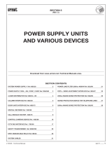
Modular panel with a tough, streamline and modern design for
simple access to a full range of functions. The system consists of
modules (with or without black or white plastic front panels) which
can be inserted on specic frames. It has IK08 classied protection
against external impacts is certied with degree, and IP55 classied
resistance to liquid and micro-dust penetration. The ush-mounting
boxes or wall-mounted casings can be coupled by means of shims to
create various panel types and congurations with a small number of
components. The advantage of needing to stock fewer components
is relevant for both wholesalers and installers. The modules can be
installed simply using the connecting wires (with connectors) supplied
in the kit and the removable connectors (with carriage) for connecting
to the system.
The gure above shows an example consisting of the following
products:
• Audio-video door unit (Ref. 1083/48) with 1-button front panel
(Ref. 1168/141).
• 4-button modules (Ref. 1168/4) with 4-button front panel (Ref.
1168/14).
• Building number module (Ref. 1168/50 - optional).
• ILA and voice synthesis module (Ref. 1168/48 - optional).
FEATURES
• Single module audio-video or audio door unit.
• Possibility of powering up to 12 modules in total:
– A single audio-video or audio door unit with CCTV and respective
front panel (black or white) with 0, 1 or 2 buttons.
– A single ILA and voice synthesis module (Ref. 1168/48 - optional).
– Up to 11 4-button expansion modules (Ref. 1168/4) with
respective front panels (black or white) with from 1 to 4 buttons,
for up to 45 buttons on a row.
– Up to 11 eight-button expansion modules (Ref. 1168/8) with from
4 to 8 buttons with respective front panels (black or white), for up
to 90 buttons on two rows.
– Up to 11 house number module (Ref. 1168/50 - optional).
• Basic programming using device buttons or advanced programming
via WiFi using a terminal (personal computer, smartphone or tablet).
• Protection system to prevent single module wiring.
• Optical signals via LED indicating system conditions (DDA).
• Pedestrian door electrical lock actuation with capacitance discharge
and hold current.
• Programmable pedestrian electrical lock actuation from 1 to 90
seconds.
• Hall button.
• Garage gate electrical lock actuation with dry contacts.
• Door sensor status input.
• Trimmer for adjusting speaker volume.
• Tags light activation with dusk sensor which can be deactivated.
• Wide-Angle colour camera (door unit Ref. 1083/48 only).
• Camera lighting LED (door unit Ref. 1083/48 only).
• Input for coaxial cable from CCTV camera or output from surveillance
camera device Ref. 1083/69 in case of multiple cameras “Max 4”
(door unit Ref. 1083/39 only).
• Connector for managing surveillance camera device (door unit Ref.
1083/39 only).
AUDIO VIDEO DOOR UNIT REF. 1083/48, AUDIO
DOOR UNIT REF. 1083/38 (1 MODULE) AND
DOOR UNIT WITH CCTV REF. 1083/39
STRUCTURE
FRONT VIEW
REAR VIEW 1083/38 AND 1083/48
REAR VIEW 1083/39
10 11 12 13 16
17
T+
T-
R
14 15
1. System status display LED (DDA);
2. “USER 0” calling button;
3. Speaker;
4. Name tag and button light LED;
5. Camera (door unit Ref. 1083/48 only);
6. Camera lighting LED (door unit Ref. 1083/48 only);
7. “USER 1” calling button;
8. Microphone;
9. Dusk sensor for automatically switching on the name tag lighting;
10. Trimmer for adjusting speaker volume (RV1);
11. Conguration button (PROGRAM);
12. ILA and voice synthesis connector (Sch. 1168/48);
13. Module connection wire connector (OUT);
14. Label with MAC ADDRESS of the device;
15. Jumper provided to connect the door state sensor;
16. Terminal board;
17. Connector for managing the device for surveillance cameras (door
unit Ref. 1083/39 only).
ALPHA PUSH BUTTON PANEL
AUDIO VIDEO DOOR UNIT Ref. 1083/48
AUDIO DOOR UNIT Ref. 1083/38
AUDIO DOOR UNIT WITH CCTV Ref. 1083/39
ALPHA PUSH BUTTON PANEL
1 2 3 4 5 6 7 8 9
10 11 12 13 14 1615

sec.3m
−−−−
3
2 VOICE - Technical Manual
PUSH BUTTON PANEL
DESCRIPTION OF TERMINALS
V5
Composite video signal reference (earth) (from
CCTV camera or device output for
surveillance cameras) (*)
V3
Composite video signal input (from CCTV camera
or device output for surveillance
cameras) (*)
(*) Terminals present only on door unit Ref. 1083/39.
]
PA
Hall button
]
LINE
Bus line in
]
SE2
Garage relay contacts
SE -
Pedestrian electrical lock with capacitance
discharge actuation negative
SE +
Pedestrian electrical lock with capacitance
discharge actuation positive
DESCRIPTION OF THE WIRES FOR CONNECTING
DEVICE TO SURVEILLANCE CAMERAS (FEATURE
AVAILABLE ONLY ON DOOR UNIT REF. 1083/39)
A wire is provided with the product for connecting the door unit, via
the connector (17) to and the surveillance camera control device Ref.
1083/69, for managing multiple cameras.
The camera control device Ref. 1083/69 must be set to default
conguration (default setting).
Green wire (R)
Black wire (T-)
Yellow wire (T+)
R
Surveillance camera device reset: green wire
T-
Surveillance camera control device reference (earth): black wire
T+
Surveillance camera device control: yellow wire
TECHNICAL SPECIFICATIONS
Power voltage: 36÷48 V
Consumption @ 48Vcc: 45mA max
Standby: < 10 mAcc
Full rate: < 250 mAcc
Maximum current output terminals SE+, SE-: max 5A @ 30 Vcc
Maximum current free contact (SE2): max 1A @ 30 Vcc
Wires with cross-section area of 0.5 mm
2
or larger must comply
with IEC 60332-1-2; wires with crosssection area smaller than 0.5
mm
2
must comply with IEC 60332-2-2.
DEFAULT CONFIGURATION
Parameter Function Default
Parameter 1 Door unit type Main
Parameter 2 Door unit ID Address 0
Parameter 3 Door opener Privacy
Parameter 4 Call button enabling
Both buttons
enabled
Parameter 5
Call button association with
switchboard call
Not active
OPERATION
CALLS
Up to 90 users max. can be called by pressing the respective buttons
of the push button panel associated to the camera.
DDA (Disability Discrimination Act) LED ACTUATION - SYSTEM
STATUS INDICATION
After pressing the call button, the two following cases can occur:
• Call in progress: led on green and voice message “CALL IN
PROGRESS”.
• Line engaged: led on red and voice message “THE LINE IS
BUSY”.
• Off-hook waiting time expired: voice message “THE USER IS NOT
ANSWERING”:
• Conversion in progress: led on orange;
• Door open: led green and “THE DOOR IS OPEN” voice message”.
The voice messages are possible if the audio-video door module
Ref. 1083/48 or the audio door unit Ref. 1083/38 is connected to
the ILA module Ref. 1168/48.
PEDESTRIAN LOCK ACTUATION
The door unit has two terminals for managing the pedestrian door lock
(SE+ and SE-).
The electric lock is operated in the following cases:
• whenever the hall button is pressed (terminals PA);
• when a door open command is received from an apartment station
according to the conguration (“free” or “privacy””.
GARAGE GATE LOCK ACTUATION (GATE)
The audio and audio-video door units have two terminals (SE2)
connected to the contacts of a normally open relay which can be used
to control a gate opening control unit (*). The relay is operated for 1
second after receiving the garage door opening command according
to the operating mode (“free” or “privacy”) as the door lock.
(*) The relay is NOT suitable to control direct power loads and can
only be used as control relay.
VOLUME ADJUSTMENT
Volume levels are calibrated by default so not to require adjustments
in most cases.
Use a screwdriver to adjust the speaker volume (10), if required.
ALPHA PUSH BUTTON PANEL
ALPHA PUSH BUTTON PANEL
AUDIO VIDEO DOOR UNIT Ref. 1083/48
AUDIO DOOR UNIT Ref. 1083/38
AUDIO DOOR UNIT WITH CCTV Ref. 1083/39

4
−−−−
sec.3m
2 VOICE - Technical Manual
PUSH BUTTON PANEL
ALPHA PUSH BUTTON PANEL
ILA AND VOICE SYNTHESIS MODULE REF. 1168/48
ALPHA PUSH BUTTON PANEL
ILA AND VOICE SYNTHESIS MODULE
REF. 1168/48 (BLACK) OR SCH. 1168/48W (WHITE)
The ILA and voice synthesis module is a modular device designed to
allow hearing aid users to hear the door unit audio and be notied of
system state by means of auditory indications.
In order to interface with the calling unit, the user must approach the
hearing aid (with T function) to the front part of the device, no further
than 20 cm, near the name tag .
Posizionare il
selettore
in modalità T
max 20 cm
Modulo
con posto
esterno
Modulo ILA
e sintesi vocale
Modulo tasti
STRUCTURE
REAR VIEW
1. Module connection wire connector (IN);
2. Module connection wire connector (OUT);
3. Audio wire connector (ILA);
4. Potentiometer for adjusting the speech synthesis volume;
5. Rotary selector for selecting speech synthesis.
INSTALLATION
A
B
A
A
B
A
The ILA module must be positioned immediately near the door unit.
The modules must be connected by means of the three-wire audio
cord provided.
A
6 cm long cord provided with button module and expansion unit
Ref. 1168/4 of the ILA and voice synthesis module Ref. 1168/48.
B
20-cm cord provided with ILA and voice synthesis module Ref.
1168/48
SPEECH SYNTHESIS LANGUAGE SELECTION
The language is selected by means of the rotary selector (5) in the rear
part of the module (see Structure chapter) as shown in the following
table:
Rotary selector position Associated language
1 Italian (default)
2 English
3 French
4 German
5 Spanish
6 Dutch
0 - 7 - 8 - 9 Voice messages off
Disconnect the power from the device and reconnect it to
activate the new programming.
SPEECH SYNTHESIS VOLUME ADJUSTMENT
Volumes are calibrated by default so not to require adjustments in
most cases. Use a screwdriver to adjust the volume, if required.
TECHNICAL SPECIFICATIONS
Voice message acoustic pressure ............................... 80 dB a 10 cm
Working temperature range..............................................-25 ÷ +40° C

sec.3m
−−−−
5
2 VOICE - Technical Manual
PUSH BUTTON PANEL
BUILDING NUMBER MODULE REF. 1168/50
The tags provided with the products are listed below.
Sch.1168/50 and Sch.1168/50W:
Temporary transparent name tag.
ALTO/UP
Sch.1168/50: Black name tag
supplied with the module; the
name tag can be written by
engraving.
ALTO/UP
Sch.1168/50W: Opaline white
name tag supplied with the
module; the name tag can be
written by means of decals.
ALTO/UP
INSTALLATION
OUT
OUT
IN
OUT
IN
A
6 cm long cord provided with button module and expansion
unit Ref. 1168/4 or 1168/8 of the building number module Ref.
1168/50.
C
38 cm long cord provided with building number module Ref.
1168/50.
The name tag can be tted or replaced only after having
removed the front of the module.
BLIND MODULE REF. 1168/59
This module is used to ll in spaces which are not used in modular
applications as required.
4-BUTTON MODULE REF. 1168/4
8-BUTTON MODULE REF. 1168/8
4-BUTTON MODULE 1168/4
8-BUTTON MODULE 1168/8
The 4-button or 8-button modules can be used to expand the number
of users on the panel. Up to 88 buttons can be connected (in addition
to the two already present on the door unit), using up to 11 button
modules Ref. 1168/8.
ALPHA PUSH BUTTON PANEL
BUILDING NUMBER MODULE REF. 1168/50
BLIND MODULE REF. 1168/59
BUTTON MODULE REF. 1168/4 - 1168/8
ALPHA PUSH BUTTON PANEL

6
−−−−
sec.3m
2 VOICE - Technical Manual
PUSH BUTTON PANEL
ALPHA PUSH BUTTON PANEL
FLUSH-MOUNTED PANEL ACCESSORIES
FLUSH-MOUNTED PANEL ACCESSORIES
FLUSH-MOUNTING BOXES
For different versions of ush-mounting boxes for ALPHA range
products are provided according to the number of modules to be
housed:
• For 1 module Ref. 1145/51
• For 2 modules Ref. 1145/52
• For 3 modules Ref. 1145/53
• For 4 modules Ref. 1145/54
System wires lead into the boxes through the openings on the sides
and bottom of the box.
All openings are shut by removable closures.
JOINING FLUSH-MOUNTING BOXES
Flush mounting boxes can be assembled with suitable spacers, also
used as wire hole.
Up to 3 4-module ush-mounting boxes can be assembled (12
modules in total). If wall cover frames are used, instead, up to 3
3-module boxes (9 modules in total) can be assembly, joining them
on the longer side.
All spacers are empty, to allow the passage of wires from a box to
another one.
MODULE HOLDER FRAMES
The module holder frames allow quick and easy ALPHA module
assembly (either single or double).
A hinge is provided in the lower part of the frame to tip the modules
and facilitate wiring and adjustment.
ALPHA PUSH BUTTON PANEL
Available versions are:
• For 1 module Ref. 1168/61
• For 2 modules Ref. 1168/62
• For 3 modules Ref. 1168/63
• For 4 modules Ref. 1168/64
WALL COVER FRAME
These frames are used to conceal irregularities of the wall in the
ush mounting area surrounding the panel; insert the cover frames
between modules and wall.
The following anodised aluminium frames are provided:
• 1-row frame for 1 module Ref. 1168/611
• 1-row frame for 2 modules Ref. 1168/612
• 1-row frame for 3 modules Ref. 1168/613
• 1-row frame for 4 modules Ref. 1168/614
151 mm 2,5 mm
H
H is 148, 238, 328 and 418 mm for the 1, 2, 3 and 4 module ver-
sions, respectively.
• 2-row frame for 4 modules Ref. 1168/624
• 2-row frame for 6 modules Ref. 1168/626
280 mm
H
2,5 mm
H is 238 and 328 mm for 2 and 3 module versions, respectively.

sec.3m
−−−−
7
2 VOICE - Technical Manual
PUSH BUTTON PANEL
ALPHA PUSH BUTTON PANEL
FLUSH-MOUNTED PANEL ACCESSORIES
WALL-MOUNTED PANEL ACCESSORIES
PANEL ACCESSORY IN COMMON TO BOTH VERSIONS
• 3-row frame for 9 modules Ref. 1168/639
409 mm
H
2,5 mm
H is 328 mm for 3 module versions.
WALL FRAME COVER INSTALLATION
• Embed the ush mounting box in the wall, position the wall cover
frame and fasten the module holder lower screw. Frame fastening
is completed by tightening the upper frame screw last.
Ø ≥ 4 mm
a
b
WALL-MOUNTED PANEL ACCESSORIES
CASINGS WITH FRAME
The casings can be used for wall-mounted installations without
embedding.
The following versions are provided with module holder frame:
• For 1 module Ref. 1168/311
• For 2 modules Ref. 1168/312
• For 3 modules Ref. 1168/313
• For 4 modules Ref. 1168/314
125 mm
H
20,4 mm
H is 126, 217, 306 and 396 mm for the 1, 2, 3 and 4 module versions,
respectively.
ALPHA PUSH BUTTON PANEL
CASING AND FRAME JOINER
The casings with frames may be joined by means of shims which
double as spacers. Up to 3 4-module ush-mounting boxes can be
assembled (12 modules in total).
All shims are hollow to allow the passage of wires from one box to
the other.
PANEL ACCESSORY IN COMMON TO BOTH
VERSIONS
RAIN HOOD COVER
They are useful to make the panel installation weatherproof.
• For 1 module Ref. 1168/401
The hoods are inserted instead of the upper headers.
2
CLICK!
1
1
2
3 4
5

8
−−−−
sec.3m
2 VOICE - Technical Manual
PUSH BUTTON PANEL
ALPHA PUSH BUTTON PANEL
ALPHA PUSH BUTTON PANEL INSTALLATION
ALPHA PUSH BUTTON PANEL INSTALLATION
It is suggested to install the modules at the height shown below,
according to the system to be realized.
(*) (*)
(*) For disabled or special needs users of the D1 type (elderly) and D2
type (lower limb motor difculties), the centre of the device must
be arranged at a height comprised between 75 cm and 140 cm with
respect to the oor. For more details, see technical standard CEI
64-21:2016-12 – Residential environments. Systems suited for use
by people with disabilities or special needs.
However, for complex systems with several modules, for a correct
installation consider the height shown in the gure to x the camera. If
the system is a door phone, height refers to the door unit.
FLUSH-MOUNTED VERSION
• Prepare the ush-mounting hole for the passages of the connecting
wires.
• Install the ush mounting box: it must not jut out of the wall.
ALPHA PUSH BUTTON PANEL
• Remove the upper header and the lower header from the frame
using a at screwdriver at the tip 0.
2
2
3
3
1
1
Ø ≤ 3 mm
• Fit the module holder frame.
Ø ≥ 4 mm
• Fit the modules in the frame.

sec.3m
−−−−
9
2 VOICE - Technical Manual
PUSH BUTTON PANEL
• Tip the frame and connect the wires.
• Adjust correct perpendicularity of the panel.
• Establish the connections between the various modules with the
wires provided before powering the system.
1
2
• Use the cord provided with the frame to connect modules belonging
to frames arranged side by side.
• On the last module be sure to protect the OUT connector using the
cap provided.
PROGRAM
• A PROGRAM button is present on the base of some modules (e.g.
door unit). Press this button to access advanced congurations
with WiFi connection (see specic paragraph).
• Close the frame by tightening the screws.
2
1
• Insert the name tags in the front panels Clip the front panels onto
the frame.
OK
OK
When coupling the front to the frame, make sure to keep the
buttons on the right side of the panel.
ALPHA PUSH BUTTON PANEL
ALPHA PUSH BUTTON PANEL INSTALLATION
ALPHA PUSH BUTTON PANEL

10
−−−−
sec.3m
2 VOICE - Technical Manual
PUSH BUTTON PANEL
• Attach upper header and lower the frame.
2
2
1
1
CLICK!
CLICK!
WALL-MOUNTED VERSION
• Remove the upper header and the lower header from the frame
using a at screwdriver at the tip 0.
2
2
3
3
1
1
Ø ≤ 3 mm
• Remove the module holder frame from the casing.
ALPHA PUSH BUTTON PANEL
ALPHA PUSH BUTTON PANEL INSTALLATION
• Secure the casing with screws to the wall.
• Fit the module holder frame.
Ø ≥ 4 mm
• Fit the modules in the frame.
ALPHA PUSH BUTTON PANEL

sec.3m
−−−−
11
2 VOICE - Technical Manual
PUSH BUTTON PANEL
• Tip the frame and connect the wires.
• Adjust correct perpendicularity of the panel.
• Use the cord provided with the frame to connect modules belonging
to frames arranged side by side.
1
2
• On the last module be sure to protect the OUT connector using the
cap provided.
PROGRAM
ALPHA PUSH BUTTON PANEL
ALPHA PUSH BUTTON PANEL INSTALLATION
• A PROGRAM button is present on the base of some modules (e.g.
door unit). Press this button to access advanced congurations
with WiFi connection (see specic paragraph).
• Close the frame by tightening the screws.
2
1
• Insert the name tags in the front panels Clip the front panels onto
the frame.
OK
OK
When coupling the front to the frame, make sure to keep the
buttons on the right side of the panel.
ALPHA PUSH BUTTON PANEL

12
−−−−
sec.3m
2 VOICE - Technical Manual
PUSH BUTTON PANEL
ALPHA PUSH BUTTON PANEL
ALPHA PUSH BUTTON PANEL INSTALLATION
• Attach upper header and lower the frame.
2
2
1
CLICK!
CLICK!
1
COMPLEMENTARY PRODUCTS LIST
DOOR UNIT
Audio video door unit Ref. 1038/48
Audio door unit Ref. 1083/38
Audio door unit with CCTV Ref. 1083/39
MODULES
4-Button module Ref. 1168/4
8-Button module Ref. 1168/8
ILA and voice synthesis module (*) Ref. 1168/48 / 1168/48W
Building number module (*) Ref. 1168/50 / 1168/50W
Blind module Ref. 1168/59
FRONT FRAME FOR PANEL AND DOOR UNIT (*)
1 Button front frame on 1 row Ref. 1168/11 / 1168/11W
2 Button front frame on 1 row Ref. 1168/12 / 1168/12W
3 Button front frame on 1 row Ref. 1168/13 / 1168/12W
4 Button front frame on 1 row Ref. 1168/14 / 1168/14W
4 Button front frame on 2 row Ref. 1168/24 / 1168/24W
8 Button front frame on 2 row Ref. 1168/28 / 1168/28W
0 PB front frame for audio video door unit Ref. 1168/140 / 1168/140W
1 PB front frame for audio video door unit Ref. 1168/141 / 1168/141W
2 PB front frame for audio video door unit Ref. 1168/142 / 1168/142W
0 PB front frame for audio door unit Ref. 1168/130 / 1168/130W
1 PB front frame for audio door unit Ref. 1168/131 / 1168/130W
2 PB front frame for audio door unit Ref. 1168/132 / 1168/130W
FLUSH-MOUNTING BOXES
For 1 module Ref. 1145/51
For 2 modules Ref. 1145/52
For 3 modules Ref. 1145/53
For 4 modules Ref. 1145/54
MODULE HOLDER FRAMES
Frame for 1 module Ref. 1168/61
Frame for 2 modules Ref. 1168/62
Frame for 3 modules Ref. 1168/63
Frame for 4 modules Ref. 1168/64
WALL COVER FRAME
1-row frame for 1 module Ref. 1168/611
1-row frame for 2 modules Ref. 1168/612
1-row frame for 3 modules Ref. 1168/613
1-row frame for 4 modules Ref. 1168/614
2-row frame for 4 modules Ref. 1168/624
2-row frame for 6 modules Ref. 1168/626
3-row frame for 9 modules Ref. 1168/639
CASINGS WITH FRAME
1-row frame for 1 module Ref. 1168/311
1-row frame for 2 modules Ref. 1168/312
1-row frame for 3 modules Ref. 1168/313
1-row frame for 4 modules Ref. 1168/314
RAIN HOOD COVER
For 1 module Ref. 1168/401
NAME TAGS
Set name tags Alpha single PB black Ref. 1168/100
Set name tags Alpha single PB white Ref. 1168/101
Set name tags Alpha double PB black Ref. 1168/102
Set name tags Alpha double PB white Ref. 1168/103
(*) Black or white
ALPHA PUSH BUTTON PANEL

sec.3m
−−−−
13
2 VOICE - Technical Manual
PUSH BUTTON PANEL
ALPHA PUSH BUTTON PANEL
OVERALL DIMENSIONS
ALPHA PUSH BUTTON PANEL - OVERALL DIMENSIONS
FLUSH-MOUNTED VERSION
126 / 217 / 306 / 396 mm
376 mm
254 mm
383 mm
126 / 217 / 306 / 396 mm
126 / 217 / 306 / 396 mm
114 / 204 / 294 / 384 mm
114 / 204 / 294 / 384 mm
114 / 204 / 294 / 384 mm
Dimensions H1= 114, 204, 294, 384 refers to the ush-mounting height and H2= 126, 217, 306, 396 refers to the total height, for the 1,
2, 3, 4 module versions, respectively.
WALL-MOUNTED VERSION
125 mm
254 mm
383 mm
126 / 217 / 306 / 396 mm
126 / 217 / 306 / 396 mm
126 / 217 / 306 / 396 mm
H3 referred to the total height may differ according to the number of modules that the case may contain.

14
−−−−
sec.3m
2 VOICE - Technical Manual
PUSH BUTTON PANEL
ALPHA PUSH BUTTON PANEL - VIDEO DOOR PHONE SYSTEMS
ALPHA PUSH BUTTON PANEL
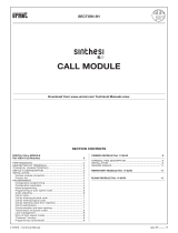
MODULARITY EXAMPLES FOR DIFFERENT SYSTEM DIMENSIONS
(VIDEO DOOR PHONE SYSTEMS WITH SINGLE PUSH BUTTON)
video door phones
BUTTONS NUMBER
1 2 3 4 5 6 7 8 9 10 11 12 13 14 15 16 17 18 19 20 21 22
Common
products
A/V door unit
module
1083/48 1 1 1 1 1 1 1 1 1 1 1 1 1 1 1 1 1 1 1 1 1 1
Front frame for
A/V door unit
1168/140 1 1 1 1 1 1 1 1 1 1 1 1 1 1
1168/141 1 1 1 1 1 1 1
1168/142 1
4-Button module 1168/4 1 1 1 2 2 2 2 3 3 3 3 4 4 4 4 5 5 5 5 6
Front frame for push
button panel
1168/11
1168/12 1 1 1 1 1 1
1168/13 1 1 1 1
1168/14 1 1 1 1 2 2 2 2 3 3 3 3 4 4 4 4 5 5 5
Building number module 1168/50
Blind module 1168/59 1 1 1 1 1
Rain hood cover 1168/401 1 1 1 1 1 1 1 1 1 1 1 1 1 2 2 2 2 2 2 2 2 2
Flush
mounting
(#)
Flush-mounting boxes
1145/51 1 1
1145/52 1 1 1
1145/53 1 1 1 1 2 2 2 2 2 2 2 2
1145/54 1 1 1 1 2
Module holder frames
1168/61 1 1
1168/62 1 1 1
1168/63 1 1 1 1 2 2 2 2 2 2 2 2
1168/64 1 1 1 1 2
Wall cover frame
(*)
1168/611 1 1
1168/612 1 1 1
1168/613 1 1 1 1
1168/614
1168/624 1 1 1 1
1168/626 1 1 1 1 1 1 1 1
1168/639
Wall
mounting
(#)
Casings with frame
1168/311 1 1
1168/312 1 1 1
1168/313 1 1 1 1 2 2 2 2 2 2 2 2
1168/314 1 1 1 1 2
1
2 3 4 5 6 7 8 9 10 11 12 13 14 15 16 17 18 19 20 21 22
BUTTONS NUMBER
(#) in alternative
(*) optional

sec.3m
−−−−
15
2 VOICE - Technical Manual
PUSH BUTTON PANEL
ALPHA PUSH BUTTON PANEL
MODULARITY EXAMPLES FOR DIFFERENT SYSTEM DIMENSIONS
(VIDEO DOOR PHONE SYSTEMS WITH SINGLE PUSH BUTTON)
video door phones
BUTTONS NUMBER
23 24 25 26 27 28 29 30 31 32 33 34 35 36 37 38 39 40 41 42 43 44 45
Common
products
A/V door unit
module
1083/48 1 1 1 1 1 1 1 1 1 1 1 1 1 1 1 1 1 1 1 1 1 1 1
Front frame for
A/V door unit
1168/140 1 1 1 1 1 1 1 1 1 1 1 1 1 1 1 1 1
1168/141 1 1 1 1 1 1
1168/142
4-Button module 1168/4 6 6 6 7 7 7 7 8 8 8 8 9 9 9 9 10 10 10 10 11 11 11 11
Front frame for push
button panel
1168/11
1168/12 1 1 1 1 1
1168/13 1 1 1 1 1 1
1168/14 5 6 6 6 6 7 7 7 7 8 8 8 8 9 9 9 9 10 10 10 10 11 11
Building number module 1168/50
Blind module 1168/59 1 1 1 2 2 2 2 1 1 1 1
Rain hood cover 1168/401 2 2 2 2 2 2 2 3 3 3 3 3 3 3 3 3 3 3 3 3 3 3 3
Flush
mounting
(#)
Flush-mounting boxes
1145/51
1145/52
1145/53 3 3 3 3
1145/54 2 2 2 2 2 2 2 3 3 3 3 3 3 3 3 3 3 3 3
Module holder frames
1168/61
1168/62
1168/63 3 3 3 3
1168/64 2 2 2 2 2 2 2 3 3 3 3 3 3 3 3 3 3 3 3
Wall cover frame
(*)
1168/611
1168/612
1168/613
1168/614
1168/624
1168/626
1168/639 1 1 1 1
Wall
mounting
(#)
Casings with frame
1168/311
1168/312
1168/313 3 3 3 3
1168/314 2 2 2 2 2 2 2 3 3 3 3 3 3 3 3 3 3 3 3
23
24 25 26 27 28 29 30 31 32 33 34 35 36 37 38 39 40 41 42 43 44 45
BUTTONS NUMBER
(#) in alternative
(*) optional
ALPHA PUSH BUTTON PANEL - VIDEO DOOR PHONE SYSTEMS

16
−−−−
sec.3m
2 VOICE - Technical Manual
PUSH BUTTON PANEL
11 1615141312
22
21
201918
28
27
262524
32
31
30
33
34
35
36
37
23
0
17
29
ALPHA PUSH BUTTON PANEL
MODULARITY EXAMPLES FOR DIFFERENT SYSTEM DIMENSIONS
(VIDEO DOOR PHONE SYSTEMS WITH SINGLE PUSH BUTTON)
ALPHA PUSH BUTTON PANEL - VIDEO DOOR PHONE SYSTEMS

sec.3m
−−−−
17
2 VOICE - Technical Manual
PUSH BUTTON PANEL
ALPHA PUSH BUTTON PANEL
MODULARITY EXAMPLES FOR DIFFERENT SYSTEM DIMENSIONS
(VIDEO DOOR PHONE SYSTEMS WITH SINGLE PUSH BUTTON)
ALPHA PUSH BUTTON PANEL - VIDEO DOOR PHONE SYSTEMS
38 39
40
41 42
44 45
43

18
−−−−
sec.3m
2 VOICE - Technical Manual
PUSH BUTTON PANEL
ALPHA PUSH BUTTON PANEL
MODULARITY EXAMPLES FOR DIFFERENT SYSTEM DIMENSIONS
(VIDEO DOOR PHONE SYSTEMS WITH DOUBLE PUSH BUTTON)
video door phones
BUTTONS NUMBER
1 2 3 4 5 6 7 8 9 10 11 12 13 14 15 16 17 18 19 20 21 22 23 24 25 26 27 28 29 30
Common
products
A/V door unit
module
1083/48 1 1 1 1 1 1 1 1 1 1 1 1 1 1 1 1 1 1 1 1 1 1 1 1 1 1 1 1 1 1
Front frame for
A/V door unit
1168/140 1 1 1 1 1 1 1 1 1 1 1 1 1 1
1168/141 1
1168/142 1 1 1 1 1 1 1 1 1 1 1 1 1 1 1
8-Button module 1168/8 1 1 1 1 1 1 1 1 2 2 2 2 2 2 2 2 3 3 3 3 3 3 3 3 4 4 4 4
Front frame for push
button panel
1168/24 1 1 1 1 1 1 1 1 1 1 1 1 1 1 1 1
1168/28 1 1 1 1 1 1 1 1 2 2 2 2 2 2 2 2 3 3 3 3 3 3 3 3
Building number
module
1168/50
Blind module 1168/59 1 1 1 1
Rain hood cover 1168/401 1 1 1 1 1 1 1 1 1 1 1 1 1 1 1 1 1 1 1 1 1 1 1 1 1 1 2 2 2 2
Flush
mounting
(#)
Flush-mounting boxes
1145/51 1 1
1145/52 1 1 1 1 1 1 1 1
1145/53 1 1 1 1 1 1 1 1 2 2 2 2
1145/54 1 1 1 1 1 1 1 1
Module holder frames
1168/61 1 1
1168/62 1 1 1 1 1 1 1 1
1168/63 1 1 1 1 1 1 1 1 2 2 2 2
1168/64 1 1 1 1 1 1 1 1
Wall cover frame
(*)
1168/611 1 1
1168/612 1 1 1 1 1 1 1 1
1168/613 1 1 1 1 1 1 1 1
1168/614 1 1 1 1 1 1 1 1
1168/624
1168/626 1 1 1 1
1168/639
Wall
mounting
(#)
Casings with frame
1168/311 1 1
1168/312 1 1 1 1 1 1 1 1
1168/313 1 1 1 1 1 1 1 1 2 2 2 2
1168/314 1 1 1 1 1 1 1 1
1
2 3 4 5 6 7 8 9 10 11 12 13 14 15 16 17 18 19 20 21 22 23 24 25 26 27 28 29 30
BUTTONS NUMBER
(#) in alternative
(*) optional
ALPHA PUSH BUTTON PANEL - VIDEO DOOR PHONE SYSTEMS

sec.3m
−−−−
19
2 VOICE - Technical Manual
PUSH BUTTON PANEL
ALPHA PUSH BUTTON PANEL
MODULARITY EXAMPLES FOR DIFFERENT SYSTEM DIMENSIONS
(VIDEO DOOR PHONE SYSTEMS WITH DOUBLE PUSH BUTTON)
video door phones
BUTTONS NUMBER
31 32 33 34 35 36 37 38 39 40 41 42 43 44 45 46 47 48 49 50 51 52 53 54 55 56 57 58 59 60
Common
products
A/V door unit
module
1083/48 1 1 1 1 1 1 1 1 1 1 1 1 1 1 1 1 1 1 1 1 1 1 1 1 1 1 1 1 1 1
Front frame for
A/V door unit
1168/140 1 1 1 1 1 1 1 1 1 1 1 1 1 1 1 1
1168/141
1168/142 1 1 1 1 1 1 1 1 1 1 1 1 1 1
8-Button module 1168/8 4 4 4 4 5 5 5 5 5 5 5 5 6 6 6 6 6 6 6 6 7 7 7 7 7 7 7 7 8 8
Front frame for push
button panel
1168/24 1 1 1 1 1 1 1 1 1 1 1 1 1 1
1168/28 4 4 4 4 4 4 4 4 5 5 5 5 5 5 5 5 6 6 6 6 6 6 6 6 7 7 7 7 7 7
Building number
module
1168/50 1 1 1 1 1 1 1 1 1 1 1 1
Blind module 1168/59
Rain hood cover 1168/401 2 2 2 2 2 2 2 2 2 2 2 2 2 2 2 2 2 2 2 2 2 2 2 2 2 2 2 2 3 3
Flush
mounting
(#)
Flush-mounting boxes
1145/51
1145/52
1145/53 2 2 2 2 2 2 2 2 2 2 2 2 3 3
1145/54 2 2 2 2 2 2 2 2 2 2 2 2 2 2 2 2
Module holder frames
1168/61
1168/62
1168/63 2 2 2 2 2 2 2 2 2 2 2 2 3 3
1168/64 2 2 2 2 2 2 2 2 2 2 2 2 2 2 2 2
Wall cover frame
(*)
1168/611
1168/612
1168/613
1168/614
1168/624
1168/626
1168/639 1 1 1 1 1 1 1 1 1 1 1 1 1 1
Wall
mounting
(#)
Casings with frame
1168/311
1168/312
1168/313 2 2 2 2 2 2 2 2 2 2 2 2 3 3
1168/314 2 2 2 2 2 2 2 2 2 2 2 2 2 2 2 2
31
32 33 34 35 36 37 38 39 40 41 42 43 44 45 46 47 48 49 50 51 52 53 54 55 56 57 58 59 60
BUTTONS NUMBER
(#) in alternative
(*) optional
ALPHA PUSH BUTTON PANEL - VIDEO DOOR PHONE SYSTEMS

20
−−−−
sec.3m
2 VOICE - Technical Manual
PUSH BUTTON PANEL
ALPHA PUSH BUTTON PANEL
MODULARITY EXAMPLES FOR DIFFERENT SYSTEM DIMENSIONS
(VIDEO DOOR PHONE SYSTEMS WITH DOUBLE PUSH BUTTON)
video door phones
BUTTONS NUMBER
61 62 63 64 65 66 67 68 69 70 71 72 73 74 75 76 77 78 79 80 81 82 83 84 85 86 87 88 89 90
Common
products
A/V door unit
module
1083/48 1 1 1 1 1 1 1 1 1 1 1 1 1 1 1 1 1 1 1 1 1 1 1 1 1 1 1 1 1 1
Front frame for
A/V door unit
1168/140 1 1 1 1 1 1 1 1 1 1 1 1 1 1
1168/141
1168/142 1 1 1 1 1 1 1 1 1 1 1 1 1 1 1 1
8-Button module 1168/8 8 8 8 8 8 8 9 9 9 9 9 9 9 9 10 10 10 10 10 10 10 10 11 11 11 11 11 11 11 11
Front frame for push
button panel
1168/24 1 1 1 1 1 1 1 1 1 1 1 1 1 1
1168/28 7 7 8 8 8 8 8 8 8 8 9 9 9 9 9 9 9 9 10 10 10 10 10 10 10 10 11 11 11 11
Building number
module
1168/50
Blind module 1168/59 2 2 2 2 2 2 2 2 1 1 1 1 1 1 1 1
Rain hood cover 1168/401 3 3 3 3 3 3 3 3 3 3 3 3 3 3 3 3 3 3 3 3 3 3 3 3 3 3 3 3 3 3
Flush
mounting
(#)
Flush-mounting
boxes
1145/51
1145/52
1145/53 3 3 3 3 3 3
1145/54 3 3 3 3 3 3 3 3 3 3 3 3 3 3 3 3 3 3 3 3 3 3 3 3
Module holder
frames
1168/61
1168/62
1168/63 3 3 3 3 3 3
1168/64 3 3 3 3 3 3 3 3 3 3 3 3 3 3 3 3 3 3 3 3 3 3 3 3
Wall cover frame
(*)
1168/611
1168/612
1168/613
1168/614
1168/624
1168/626
1168/639 1 1 1 1 1 1
Wall
mounting
(#)
Casings with frame
1168/311
1168/312
1168/313 3 3 3 3 3 3
1168/314 3 3 3 3 3 3 3 3 3 3 3 3 3 3 3 3 3 3 3 3 3 3 3 3
61
62 63 64 65 66 67 68 69 70 71 72 73 74 75 76 77 78 79 80 81 82 83 84 85 86 87 88 89 90
BUTTONS NUMBER
(#) in alternative
(*) optional
ALPHA PUSH BUTTON PANEL - VIDEO DOOR PHONE SYSTEMS
/