Page is loading ...

(Page 1)
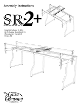
Juki Quilting Frame
Assembly and Use Instruction Manual
Copyright January 1, 2016
Jim M. Bagley, Gracewood, Inc
(Reproduction Prohibited)
Version 10
Max Overall Dimensions:
Length
Crib: 63
1
⁄4”
King: 128
1
⁄4”
Tall: 45
3
⁄4” - 51
3
⁄4”
Wide: 42”

(Page 2)
Parts List ....................................................... 3
Hardware Box .............................................. 3
(Inside Box 1) .............................................. 3
Box 1 Contents ............................................ 3
Box 2 Contents ............................................ 4
Box 3 Contents ............................................ 4
Box 4 Contents ............................................ 4
Frame Assembly ........................................... 5
Step 1: Corner Brace Assembly ..................... 5
Step 2: King Table to Frame Ends .................. 6
C rib Table to Frame Ends ................. 7
Step 3: King Table Surface ........................... 7
Crib Table Surface ........................... 8
Step 4: King Rail-Assembly ............................ 9
C rib Rail-Assembly .........................10
Sewing Machine Prep ..................................11
Step 5: Dampening Plate and Wheels ...........11
Step 6: Sure Stitch ......................................12
Step 7: Front Handles ..................................12
Step 8: LCD ................................................13
Step 9: Encoders .........................................13
Step 10: Sewing Machine Placement ............. 14
Step 11: How to Adjust Track and Rails .........16
Step 12: Handwheel ....................................16
Time to Quilt ................................................17
The Fabri-Fast Quilting Concept: ................... 17
Fabric Overview: .........................................17
Leader Cloth ...............................................18
How to Make Leader Cloth: ..........................18
Installing Fabric Layers To The Rails .............19
Step 1: Quilt Top .....................................19
Step 2: Quilt Backing ...............................19
Step 3: Batting ........................................ 19
Step 4: Quilt Fabric to Take-Up Rail ..........20
Quilt Backing ........................................20
Batting .................................................20
Quilt Top ............................................... 20
Bungee Clamps ...........................................21
Rolling Fabric ..............................................21
J uki Laser ....................................................22
Leveling Feet Adjustment .............................22
Juki Handle Adjustment ...............................23
Tips and Trouble Shooting ............................23
Contents
SAFETY INSTRUCTIONS
Read all instructions before using.
When using this machine, basic safety precautions should always be taken, including the following:
DANGER - To reduce the risk of electric shock:
• A quilting machine should never be left unattended when plugged in. Always unplug the machine from the
electrical outlet immediately after using and before cleaning.
WARNING -
• Never operate this system if it has a damaged cord or plug, if it is not working properly, if it has been
dropped or damaged. Return the system to the nearest authorized dealer for repair or adjustment.
• Keep ngers away from all moving parts.
• To disconnect, always turn the power button to the off position before unplugging any cables.
• Keep the machine and frame free from the accumulation of lint, dust, and loose cloth.
• Do not unplug by pulling on cord. To unplug, grasp the plug, not the cord.
• To reduce risk of injury have 2 people assemble the frame.

(Page 3)
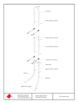
Left Frame End (1)
Right Frame End (1)Middle Leg (1)
Handwheel (1)
Track Support
Coupler (2)
M10 x 120mm
SBHCS (1)
M8 x 16mm
SBHCS (30)
M6 x 15mm
Connector Bolt
(16)
M6 x 10mm
Set Screw (8)
Box 1 Contents
M10 Washer (1)
Parts List
3mm Allen Wrench (1) 4mm Allen Wrench (1) 5mm Allen Wrench (1) 6mm Allen Wrench (1)
Fabri-Fast
Tool (1)
Wrench 13mm
and 10mm (1)
Tie Mount (3) Rubber Stopper (1)Zip Tie (3)
Hardware Box
(Inside Box 1)
Bungee Clamp (4) Bungee
Lock (4)
Fabri-Fast Tubing (4)
Corner
Brace (4)

(Page 4)
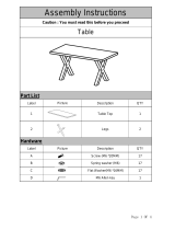
Table Structure (2)
Table Surface (2)
LCD (1)
Front
Handles (1)
Sure Stitch (1)
Top Encoder
(Black Spring) (1)
Bottom Encoder
(Silver Spring) (1)
Laser (1)
Bottom Plate (1)
Box 2 Contents
Box 4 Contents
Track
Support (4)
Rail with Ratchet
End Cap (5)
Rail with Rolling
End Cap (5)
Rail Coupler (5)
Box 3 Contents
M6 Jam Nut (8)M6 Lock Washer (4)
Rubber
Dampener (4)
M6 Washer (4)
Machine Dampening
Plate (1)
M6 x 10mm
SBHCS (3)
4mm Allen
Wrench (1)
5mm Allen
Wrench (1)
2.5mm Allen
Wrench (1)
2mm Allen
Wrench (1)
10 ft Plastic Track (4) 5 ft Plastic Track (4)
HDMI cable (1) Short Upper Encoder Cable (1) Long Lower Encoder Cable (1)
M4 x 16mm
SBHCS (1)
M3 x 16mm
SBHCS (1)

Frame Assembly
Step 1: Corner Brace Assembly
(Page 5)
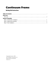
1-1: Start by adjusting the height of the Legs on the Left
and Right Frame Ends.
Note: Use the Height of Fabric Chart to determine which
height will be the most comfortable for you while stitching
your quilt. As a starting guide, we recommend starting at the 4th hole
for people between 5’ 4” and 5’ 8”. If you’re taller, you may want to use
a higher hole. If you’re shorter, you may want to use a lower hole.
1-2: Remove the M8 x 55mm SBHCS from the Frame Ends as shown in
Fig. 1-1 using the provided 4mm Allen Wrench, and the Wrench 13mm
and 10mm. Now adjust the Legs to the height which you determined
using the Height of Fabric Chart. Re-secure the Hardware, but don’t
over tighten the Nylock Nut, as it is possible to deform the Legs if over
tightened.
1-3: Adjust the height of the middle leg by setting them at the same
hole as you set the Frame End’s Legs. It will be necessary to count the
hole position as you slide the upper part of the leg up from the lowest
hole upward to make sure the middle leg is set to the same height as the Frame Ends.
1-4: Next, attach the Corner Braces to the Frame Ends as shown in Fig. 1-2. Use the 5mm Allen Wrench to
tighten the M8 x 16mm SBHCS Screws, by inserting the short end of the Allen Wrench into the Screw, and
turn while holding the long end of the Allen Wrench. This will help you to adequately tighten the Screws while
requiring less force, compared to holding the Allen Wrench by its short end.
Parts Needed:
1- Left Frame End
1- Right Frame End
1- Middle Leg
4- Corner Brace
8- M8 x 16mm SBHCS
Tools Required:
4mm Allen Wrench
5mm Allen Wrench
Wrench 13mm and 10mm
M8 x 55mm SBHCS
M8 Washer
M8 Nylock Nut
Fig. 1-1
Fig. 1-2
Corner
Brace
M8 x
16mm
SBHCS
Height of Fabric Chart
Top Hole: 40”
6
th
Hole: 39”
5
th
Hole: 38”
4
th
Hole: 37”
3
rd
Hole: 36”
2
nd
Hole: 35”
1
st
Hole: 34”
(For People between
5’ 4” and 5’ 8”)
Taller
Shorter

Step 2: King Table to Frame Ends
(Page 6)
2-1: Set the table structure on top of the brackets
and middle leg as shown Fig. 2-1a. It is advised that a
second person hold one end for stability. Secure one of
the table structures to the right Frame End and one to
the left Frame End using M8 x 16mm SBHCS Screws,
and the 5mm Allen Wrench (Fig. 2-2a and Fig. 2-2b).
2-2: Use the 5mm Allen Wrench to fasten the Middle
Leg to the middle of the Frame using M8 x 16mm
SBHCS Screws (Fig. 2-2c).
2-3: Repeat step 2-1 and 2-2 for the right side of the
table structure.
Note: Tighten each Screw a little at a time,
alternating screws. When all of the screws are tight,
the top surfaces of both Table Structures should be
even with each other.
Parts Needed:
1- Left Frame End
1- Right Frame End
1- Middle Leg
2- Table Structure
12- M8 x 16mm SBHCS
Tools Required:
5mm Allen Wrench
Fig. 2-1a
M8 x 16mm
SBHCS
Fig. 2-2a
Fig. 2-2c
Fig. 2-2b
Fig. 2-3

Crib Table to Frame Ends
Step 3: King Table Surface
(Page 7)
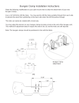
2-1-C: Secure the table structure to both of the
Frame Ends using M8 x 16mm SBHCS Screws, and the
5mm Allen Wrench (Fig. 2-4a, Fig. 2-4b, and Fig. 2-5).
3-1: Before placing the Table Surface onto the Table
Structure remove the backing from the Double Sided
Tape, located in the center of the Table Structures
(Fig. 3-1).
3-2: Place the Table Surfaces onto the Table
Structures. Center the Table Surface, so that there
is an even amount of the Table Structure showing on
both sides (Fig 3-2).
3-3: Insert a Track Support Coupler into the end of
a Track Support, so approximately half of the Coupler
is exposed (Fig 3-3).
Parts Needed:
1- Left Frame End
1- Right Frame End
1- Table Structure
8- M8 x 16mm SBHCS
Tools Required:
5mm Allen Wrench
Fig. 2-4a
M8 x 16mm
SBHCS
Fig. 2-4b
Parts Needed:
2- Table Surface
4- 10 Foot Plastic Track
4- Track Support
2- Track Support Coupler
8- M6 x 10mm Set Screw
16- M6 x 15mm Connector Bolt
Tools Required:
3mm Allen Wrench
Fig. 3-2
Right
Left
Front
Standard Frame
Reference Orientation
Double Sided Tape
Fig. 3-1
Back
Fig. 2-5
Note: Perform the steps titled crib only if you are
setting your frame up in crib size.

Crib Table Surface
(Page 8)
3-4: Secure the Track Support Coupler into the Track
Support using the 3mm Allen Wrench, and (2) M6 x
10mm Set Screws.
3-5: Insert the exposed end of the Track Support
Coupler into the end of an unused Track Support.
3-6: Secure the Track Support Coupler to the Track
Support using (2) M6 x 10mm Set Screws, and tighten with the 3mm Allen
Wrench. Make sure that the surfaces of the Track Supports are aligned with
each other, and that there is no gap between them. Build the Remaining
Track Support as done in steps 3-2 to 3-5.
3-7: Insert a piece of 10 Foot Plastic Track into each of the Track Slots, in
each of the Track Supports. (Install 2 full length pieces of Track into each
assembled Track Support, as shown in Fig. 3-4.)
3-8: Align (1) Track Support to the back of the
Table Structure so that it is ush and so that the
Track support overlaps over the table surface as
shown in Fig. 3-5. Partially secure it using
the (8) M6 x 15mm Connector Bolt from
underneath the table structure as shown in
Fig. 3-6. After all of the Bolts have been
inserted, verify the track is straight and ush
with the Table Structure and securely tighten
all Bolts.
3-9: Now attach a Track Support to the front
of the Table Structure, but this time leave
the Bolts a turn loose. You will adjust and
secure the width of this Track Support in
step 11.
3-1-C: Before placing the Table Surface onto the Table
Structure remove the backing from the Double Sided Tape,
located in the center of the Table Structures (Fig. 3-7).
3-2-C: Place the Table Surface panel onto the Table
Structure. Center the Table Surface, so that there is an
even amount of the Table Structure showing on both sides.
A
DETAIL A
SCALE 1 : 2
Fig. 3-3
Fig. 3-6
Fig. 3-5
M6 x 10mm
Set Screw
M6 x 15mm
Connector Bolts
Fig. 3-4
Plastic Track
Parts Needed:
1- Table Surface
4- 5 Foot Plastic Track
4- Track Support
8- M6 x 15mm Connector Bolt
Tools Required:
4mm Allen Wrench
Double Sided Tape
Fig. 3-7
Right
Left
Front
Back
Standard Frame
Reference Orientation
Fig. 3-8
Track Support
Flush
Table surface

Step 4: King Rail-Assembly
(Page 9)
3-3-C: Insert a piece of 5 Foot Plastic Track into each of the Track Slots, in
each of the Track Supports. (Install two 5 foot full length pieces of Track into
each Track Support, as shown in Fig. 3-9.)
3-4-C: Align a Track Support Flush to the back of the Table Structure.
Partially secure the (8) M6 x 15mm Connector Bolts. After all of the Bolts
have been inserted, verify the track is straight and
Flush to the back of the Table Structure and securely
tighten all Bolts (Fig. 3-10).
3-5-C: Now attach a Track Support to the front of the
Table Structure, but this time leave the Bolts a turn
loose (Fig. 3-10). You will adjust and secure the width
of this Track Support in step 11.
M6 x 15mm
Connector Bolts
Fig. 3-10
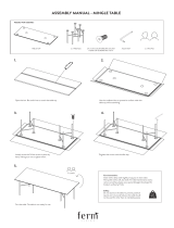
M6 X 15mm Socket Head Screw
(Pre-assembled in rail couplers)
Fig. 4-1
Rail
Rail Coupler
Parts Needed:
5- Rail with Ratchet End Cap
5- Rail with Rolling End Cap
5- Rail Coupler
Tools Required:
3mm Allen Wrench
Rail Rolling
End Cap
Rail Ratchet
End Cap
Fig. 4-2
Fig. 3-9
Plastic Track
4-1: Slide a Rail Coupler into a Rail with Ratchet End Cap. Align the holes on
the Rail with the holes in the Rail Coupler. Tighten the (2) pre-installed M6 X
15mm Socket Head Screws using the 4mm Allen Wrench. (Locations shown in
Fig. 4-1.)
4-2: Now, slide a rail with Rolling End Cap onto the exposed end of the Rail
Coupler. Align the holes, then tighten the Socket Head Screws using the 3mm
Allen Wrench, as done in Step 4-1.
4-3: Repeat Steps 4-1 and 4-2 to build the remaining 4 Rails.
Note: Put the assembled Rails on the oor in front of the Quilting Fame, with
the Ratchets to the right end. You will install the Rails after you place your
Sewing Machine onto the Quilting Frame in Step 10.

Crib Rail-Assembly
(Page 10)
4-1-C: Using the 6mm Allen Wrench, loosen the M10 x 85mm SBHCS in the Rolling End Cap, but do not
completely unthread it. Loosen the bolt until it protrudes just beyond the Rolling End Cap. Hold the rail
vertically with the rolling end cap down and tap the protruding bolt head on the oor. This will free the
compressed end cap from the rail. Then remove the Rolling End Cap from the rail (Fig. 4-3).
4-2-C: Now, slide the Rolling End Cap into the exposed end of a Rail with Ratchet End Cap. Press the Rolling
End Cap into the rail until it is ush with the end of the rail.
4-3-C: Using the 6mm Allen Wrench tighten the M10 x 85mm SBHCS completely.
4-4-C: Repeat Steps 4-3 and 4-4 to build the remaining 4 Rails.
Note: Put the assembled Rails on the oor in front of the Quilting Fame, with the Ratchets to the right end.
You will install the Rails after you place your Sewing Machine onto the Quilting Frame in Step 12.
Fig. 4-4
Parts Needed:
5- Rail with Ratchet End Cap
5- Rail with Rolling End Cap
Tools Required:
6mm Allen Wrench
End Cap
Expansion
Cone
Rolling End Cap
M10x85 SBHCS
Fig. 4-3

Sewing Machine Prep
Step 5: Dampening Plate and Wheels
(Page 11)
5-4: Attach the Machine Dampening Plate and Wheels to your Juki Quilt Virtuoso Pro by inserting the
threaded rods of the Rubber Dampeners into the holes on the Dampening Plate as shown in Fig. 5-4. Slide
(1) M6 Washers, (1) M6 Lock Washers, and (1) M6 Jam Nuts over each threaded rod and tighten using the
M10 Wrench.
M6 Lock Washer
M6 Washer
Rubber Dampener
M6 Jam Nut
M6 Jam Nut
5-2: Insert the short end of (2) Rubber Dampeners into the holes of each previously removed Mounting Plate
as shown in Fig. 5-2. Tighten (1) M6 Jam Nuts onto the end of each bolt using the 10mm Wrench.
5-3: Re-install the 2 Mounting plates using a 5mm Allen Wrench. Be sure that the Rubber Dampener side of
each plate is pointing towards the middle of the machine as show in Fig. 5-3.
5-1: Using a 5mm Allen Wrench, remove the 2 screws from each of the 2 Mounting Plates from each end of
the bottom of the Juki Machine as shown in Fig. 5-1.
Fig. 5-2
Fig. 5-3
Fig. 5-4
Fig. 5-1
Parts Needed:
1- Juki Quilt Virtuoso Pro
2- Sewing Machine Wheels
4- M6 Lock Washer (4)
5- M6 Washer (4)
6- M6 Jam Nut (8)
7- Machine Dampening Plate (1)
8- Rubber Dampener (4)
Tools Required:
1- 13mm and 10mm Wrench
1- 5mm Allen Wrench

Step 6: Sure Stitch
Step 7: Front Handles
(Page 12)
6-1: Align the Connectors on the Sure-Stitch with the Connectors located at the back of your Sewing
Machine and press rmly to join the two items.
6-2: Attach the Sure-Stitch and Juki Quilt Virtuoso Pro with a M3 x 16mm SBHCS.
7-1: Remove the Hopping Foot Mechanism
Guard, by removing the Screws indicated with “D”,
using a Phillips Screw Driver.
7-2: Secure the Front Handles to your Sewing Machine
using (3) M6 x 10mm SBHCS (See “A”), and the 4mm Allen
Wrench. Make sure that the Cable coming out of the Handles
exits the Notch in the left side of the Handlebar Housing.
7-3: Align the Cable Connector “B” with the Connector in your Sewing Machine “C” and press rmly to
connect the handles to the machine. Use a M4 x 16mm SBHCS to fasten Cable Connect “B” to the Juki Quilt
Virtuoso Pro as shown in Fig. 7-2.
7-4: Place a Ziptie Cable Mount
to the body of the machine inside
the 2 lever arm supports as shown
in Fig. 7-2. Secure the cable with
a ziptie and trim off the end with
scissors.
7-5: Guide the Cable through
the 2 Notches near the top of the
Hopping Foot Mechanism Guard,
then re-attach the Guard to your
Sewing Machine.
Ziptie Cable
Mount
M4 x 16mm
SBHCS
Fig. 7-2
Fig. 7-1
Parts Needed:
1- Juki Quilt Virtuoso Pro
1- Sure-Stitch
1- M3 x 16mm SBHCS
Tools Needed:
2mm Allen Wrench
Parts Needed:
1- Juki Quilt Virtuoso Pro
1- Front Handles
3- M6 x 10mm SBHCS
1- M4 x 16mm SBHCS
1- Ziptie Cable Mount and Ziptie
Tools Needed:
Phillips Screwdriver (not provided)
2.5mm Allen Wrench
4mm Allen Wrench
D
B
A
C
Fig. 6-1
Connectors
M3 x 16mm
SBHCS
Fig. 6-2

Step 9: Encoders
(Page 13)
8-1: Take the HDMI cable end (HDMI connector Type A see gure
8-1) and plug it into the front handles. Pass the cable through the
LCD from the bottom (Fig. 8-2).
8-3: Clip the LCD into the front handles (Fig. 8-3).
8-2: Tilt the LCD Screen back ad plug the other HDMI cable end
(HDMI connector Type D see gure 8-1) into the LCD (Fig. 8-4).
9-1: Before attaching the Encoders, use the
2mm Allen Wrench to loosen the Set Screw in
each of the Lock Collars, so that the Encoder
Wheel Bolt can turn freely.
9-2: (Sewing Machine)
Use the 4mm Allen Wrench to remove the M6 x
16mm SBHCS Screw from the outer, right, rear
wheel, in the sewing machine. (See Fig 9-1a)
9-3: Put the Wheel, which you just removed,
onto the Top Encoder (Black Spring) Wheel Bolt,
with the Flanged Hub Facing out.
9-4: Hold the Top Encoder upright to prevent
the spacers from falling off and use the 4mm
Allen Wrench to fasten the Top Encoder Wheel
Bolt into the hole made available in Step 9-2.
Top Encoder (Black Spring)
Parts Needed:
1- LCD
1- Front Handles
1- HDMI cable
Step 8: LCD
Fig. 8-1
Fig. 8-2
HDMI Connector Type D
HDMI Connector Type A
Fig. 8-3
Fig. 8-4
Parts Needed:
1- Juki Quilt Virtuoso Pro
1- Top Encoder (Black Spring)
1- Bottom Encoder (Silver Spring)
1- Bottom Plate
Tools Needed:
4mm Allen Wrench
2mm Allen Wrench
Fig. 9-1b
Fig. 9-1a
Encoder
Wheel Bolt
Flanged Side of
Wheel Hub (Taller)

Step 10: Sewing Machine Placement
(Page 14)
9-5: (Bottom Plate)
Use the 4mm Allen Wrench to remove the M6 x 16mm
SBHCS Screw from the outer, right, rear wheel, in the
Bottom Plate (See Fig 9-2).
9-6: Put the Wheel, which you just removed, onto
the Bottom Encoder (Silver Spring) Wheel Bolt with the
Flanged Hub Facing out.
9-7: Hold the Top Encoder upright to prevent the
spacers from falling off and use the 4mm Allen Wrench
to fasten the Encoder Wheel Bolt into the hole made
available in Step 9-5.
9-8: Keep the Spare Bolts with your Quilting Frames’
spare parts.
Note: Leave the Encoder Set Screws loose. They will
be tightened in Step 10.
10-1: Align the Wheels on the Bottom Plate with the
Table Track, then place it onto the Quilting Frame,
while holding the encoder so that it pivots toward the
other set of wheels on the carriage as shown in Fig.
10-1.
10-2: Now, align the Wheels on the Sewing Machine
with the Plastic Track on the Bottom Plate, while
holding the encoder so that it pivots toward the front
set of wheels of the sewing machine as shown in Fig.
10-1. (The Sewing Machine placed on Bottom Plate
will commonly be called the Carriage throughout the
remainder of this manual.)
10-3 Push the Lock Collar on each encoder up about
90 degrees or until you feel it adequate springing
back and tighten the set screw using the 2mm Allen
Wrench. (see Fig. 10-2)
90 degrees
up
90 degrees
up
Top Encoder (Black Spring)
Bottom Encoder (Silver Spring)
Bottom Encoder (Silver Spring)
Fig. 9-2
Parts Needed:
1- Juki Quilt Virtuoso Pro
1- Short Encoder Cable
1- Long Encoder Cable
1- Tie Mount
1- Zip Tie
1- Rail
Tools Needed:
2mm Allen Wrench
Fig. 10-1
Fig. 10-2
Set Screw
Lock Collar
Silver Colored
Spring

(Page 15)
10-4: (Idler Rail)
Roll the Sewing Machine to the far right
end of the quilting frame. (As shown in
Fig. 10-3)
10-5: Place the Ratchet End of a Rail
through the Throat of your Sewing
Machine, and into the Lower Ratchet Rail
Holder. Push the other end of the Rail
into the Lower Non-Ratchet Rail Holder,
at the other end of the Quilting Frame.
Push on the plastic rail end directly, it is
designed to be a tight t. (At this point
your Sewing Machine is safe to leave
unattended on your Quilting Frame.)
10-6: Plug the Short Encoder Cable into the forward
most connector in the Sure Stitch. Plug the other end
of this Cable into the Top Encoder.
10-7: Plug the Long Encoder Cable into the 2nd
Connector in the Sure Stitch. Plug the other end of
this Cable into the Bottom Encoder.
10-8: To prevent the Long Encoder Cable from
interfering with Carriage movement, apply a Tie Mount
to the back of the Carriage as shown in Fig. 10-4. Use
a Zip Tie to secure the Long Encoder Cable vertically
to the Tie Mount. Allow a small amount of extra Cable
on the Encoder side of the Tie Mount before tightly
securing the Cable with the Zip Tie. Trim the end of
the Zip Tie using Utility Scissors.
10-9: To prevent the Short Encoder Cable from
interfering with Carriage movement, apply a Tie Mount
to the end of the Top plate extrusion and secure the
short Encoder Cable using a zip tie as shown in Fig. 10-4. Allow a small amount of extra Cable on the Encoder
side of the Tie Mount before tightly securing the Cable with the Zip Tie. Trim the end of the Zip Tie using
Utility Scissors.
10-10: Test front to back Carriage travel to make sure that the Encoder Cables allow the full range of
Carriage movement, as well as staying off of the Table Surface, and the Plastic Tracks.
Right Frame End
All Ratchet Ends
Left Frame End
All Non-Ratchet Ends
Fig. 10-3
Tie Mount
Short Encoder Cable
Top Encoder (Black Spring)
Bottom Encoder (Silver Spring)
Long Encoder Cable
Fig. 10-4

Step 11: How to Adjust Track and Rails
(Page 16)
11-1: Aligning Wheels to the Track (Fig 11-1). Using
the 5mm Allen Wrench, loosen each of the bolts holding the
wheels to the extrusions on the side of the sewing machine
with the slots. Roll the machine slowly to the front and back
of the carriage. Tighten the bolts again.
11-2: Align Front Track Slowly roll the Carriage from
one end of the Quilting Frame to the other several times. This will adjust the Track so that it is centered under the Front
Wheels and parallel to one another. Once adjusted, move the sewing machine to one end of the frame and using the
4mm Allen Wrench, tighten each of the (8) M6 x 12mm Connector Bolts as you roll the machine above each one.
11-3: Remaining Rails Install the 4 remaining rails, as done previously, into the remaining Rail locations (Fig 11-2).
Parts Needed:
4- Rails (Assembled is step 4)
Take-Up Rail
Idler Rail
Quilt Back
Quilt Top
Batting
Fig. 11-2
Fig. 11-1
Slots

Step 12: Handwheel
(Page 17)
12-1: Using the 6mm Allen Wrench,
remove the Socket Head Screw out of the
Take-Up Rail Ratchet End Cap, but leave the
Ratchet End Cap in the Rail. (As shown in
Fig. 12-1.)
12-2: Place the M10 x 120mm SBHCS
through the M10 washer, and then the
Handwheel. (See Fig. 12-2)
Note: The Handwheel Coupler ships pre-
installed in the Handwheel
12-3: Align the teeth in the Handwheel
Coupler, so that they interlock with the
teeth in the Ratchet End Cap. Now using
the 6mm Allen Wrench, tighten the M10 x
120mm SBHCS into the Ratchet End Cap.
Handwheel
Remove M10 x 85mm
SBHCS
Rail
Ratchet End Cap
Handwheel Coupler
M10 x 120mm SBHCS
M10 Washer
Fig. 12-2
Parts Needed:
1- Handwheel
1- Handwheel Knob
1- Handwheel Shoulder Bolt
1- Handwheel Coupler
1- M10 x 120mm SBHCS
1- M10 Washer
Tools:
6mm Allen Wrench
Fig. 12-1
Remove Bolt

(Page 18)
Time to Quilt
The Fabri-Fast Quilting Concept:
Your quilting frame has specially designed Fabri-Fast rails. Installing your fabric is easier on The Grace Company
Brand Quilting Frames than on any other brand of quilting frame.
Each
rail has a Fabri-Fast slot, accompanying Plastic Tubing, and a Fabri-Fast Tool included with the Quilting
Frame. These components work together to make your fabric installation much easier and faster than using tape, or
tacks.
We recommend you begin using your
Quilting Frame
on some
Practice Fabric before making an actual Quilt
so that you can experiment with Machine Settings and
Stitch Techniques. Keep in mind that picking out bad
stitches is a lot of work, especially on a delicate pieced
Quilt Top.
Note: As you prepare your
Fabric Layers, we recommend making the Quilt Backing about 12” longer and 2-4”
wider than your
Quilt Top. This will allow for a little give in the Quilt Backing. This is especially useful if using thicker
batting.
Fabric Overview:
This is an outline to show which Quilt Layer goes onto each rail.
Step 1: Install Quilt Top to the Quilt Top Rail and
roll up.
Step 2: Install Quilt Backing to Backing Rail and
roll up.
Step 3: Install Batting to Batting Rail and roll up.
Step 4: Attach all Quilt Layers to Take-up Rail.
Take-Up Rail
Idler Rail
Quilt Back
Quilt Top
Batting
Release Lever Top
Release Lever Bottom
Take-Up
Idler
Backing
Top
Batting
The Idler raIl
is not considered
a Working Rail,
since it won’t
have fabric
attached directly
to it.
Fig. FS-1
Fig. FS-2
Fig. FS-3

(Page 19)
Leader Cloth
Attaching a piece of fabric (Leader Cloth) to each of your working rails will allow you to pin your Quilt Fabric to
the Leader Cloth. The Grace Company also proudly offers Leader Cloth, “Start-Right Cloth Leaders”, which can be
purchased from your preferred dealer.
How to Make Leader Cloth:
LC-1: (Selecting your cloth leader
material)
We recommend using a quality Muslin or similar
fabric that has a high thread count. Be aware
however, that if the fabric is too thick, it may be
difcult to install it into the rail’s Fabri-Fast slot.
LC-2: Surge or hem your Cloth Leaders on all
edges.
LC-3: Position Cloth Leaders so that their widths are as shown in the diagram to the right,and make the length 6”
shorter than your Rails.
LC-4: Make a light line along the entire length of your Leader Cloth about ½” in from the edge. You will use this
as a guide to help you insert the Leader Cloth into the Rails’ Fabri-Fast Slot in a straight line.
(OPTIONAL): For an easier Leader Cloth installation, you may consider making a Casing, then push the Fabri-
Fast Tubing into the Casing before installing it into the Fabri-Fast Slot. To do this, create a Casing on one edge of
each Leader Cloth by folding over the fabric one inch (1”), sew, using your Conventional Sewing Machine Presser
Foot as a guide, stitching the fabric together 3/4” from the fold. This will leave about ¼” of fabric beyond the
stitching. Leave the edges open on both ends. You may then slide your fabri-fast tubing into the casing.
LC-5: Mark each Cloth Leader at the center (length-wise).
LC-6: Mark (or stitch in a contrasting color) a straight line about ½” in from the opposite (non-casing, or non-
marked) end of the Leader Cloth. This will be the line to which you attach your Quilt Fabric Layers.
LC-7: Center your leader cloth lengthwise along the rail. Using Grace’s Fabri-
Fast
TM
System, take a piece of Fabri-Fast plastic tubing holding your cloth leader to
the Fabri-Fast slot (lining up the light line), and press the Fabri-Fast tubing over
the leader Cloth and into the Fabri-Fast slot.
LC-8: Use the Fabri-Fast tool to press the rest of the Fabri-
Fast tube and fabric in the slot. If you have made
a casing, line up the casing with the
Fabri-Fast tubing over the Fabri-Fast slot
and press it into the Fabri-Fast slot using
the Fabri-Fast tool.
Note: The illustration to the right shows
how the cloth leaders will look when
installed on each rail prior to your quilt
layers being installed.
18"
24"
Top Leader
Backing Leader
3/4" Casing
Center Marks
3/4" Casing
18"
Take-Up Leader
3/4" Casing
Take-Up
Leader
Quilt Top
Leader
Quilt Back
Leader
Fig. FS-4
Fig. FS-5
Fig. FS-6

(Page 20)
Installing Fabric Layers To The Rails
Step 1: Quilt Top
(After the quilt top fabric is rolled onto the rail the nished side of
fabric will be up)
QT-1: Fold your quilt top accordion style on the quilting table.
QT-2: Arrange the quilt top fabric so that the edge which will be
the quilt’s bottom edge is on top of the folded up fabric, with the
nished side facing up, and its free edge facing the front of the
quilting frame.
QT-3: Line up the center of your quilt top with the center of the
quilt top leader Cloth.
QT-4: Pin the bottom edge of your quilt top to the quilt top leader cloth.
Do not stretch or pull the fabric during this process. Let the fabric lay as natural as possible.
QT-5: Carefully roll the Quilt Top Rail until the Leader Cloth and quilt top are completely rolled onto the
rail. Make sure the fabric’s edges stay lined up. Smooth out any wrinkles as you roll by brushing the fabric
from the center out, being very careful not to stretch or pull the fabric.
Step 2: Quilt Backing
(After the quilt back fabric is rolled onto the rail the nished side
of fabric will be down)
QB-1: Fold your quilt back accordion style on the quilting table.
QB-2: Arrange the quilt back fabric so that the edge which will
be the quilts bottom edge is on top of the folded up fabric, with
the nished side facing down, and its free edge facing the front
of the quilting frame.
QB-3: Line up the center of your quilt back with the center of
the quilt back leader Cloth.
QB-4: Pin the bottom edge of your quilt back to the quilt back
leader cloth.
Do not stretch or pull the fabric during this process. Let the
fabric lay as natural as possible.
QB-5: Carefully roll the Quilt Back Rail until the leader Cloth and quilt back are completely rolled onto the
rail. Make sure the fabric’s edges stay lined up. Smooth out any wrinkles as you roll by brushing the fabric
from the center out, being very careful not to stretch or pull the fabric.
Step 3: Batting
(A light, bonded batting works best for machine quilting, and is recommended.)
B-1: Center the batting on the batting rail.
Quilt Top Leader
Quilt Top
Finished Side
Up
Front of
Frame
Quilt Back
Leader
Quilt Back
Finished
Side Down
Right Frame End
(Details removed for
clarity)
Fig. FS-7
Fig. FS-8
/