Page is loading ...

Sukhoi SU-26MM SE
Assembly Manual

2 Hangar 9 Sukhoi SU-26MM SE
WARNING: Read the ENTIRE instruction manual to
become familiar with the features of the product before
operating. Failure to operate the product correctly can result
in damage to the product, personal property and cause
serious injury.
This is a sophisticated hobby product and NOT a toy. It must
be operated with caution and common sense and requires
some basic mechanical ability. Failure to operate this Product
in a safe and responsible manner could result in injury or
damage to the product or other property. This product is not
intended for use by children without direct adult supervision.
Do not attempt disassembly, use with incompatible
components or augment product in any way without the
approval of Horizon Hobby, Inc. This manual contains
instructions for safety, operation and maintenance. It is
essential to read and follow all the instructions and warnings
in the manual, prior to assembly, setup or use, in order to
operate correctly and avoid damage or serious injury.
Introduction
Congratulations on the purchase of your new Hangar 9
Sukhoi SU-26MM SE. As of right now, all that stands
between you and your first flight with it is about a day’s
worth of final assembly. We’ve already installed five
Spektrum A6030 digital high-torque servos and their
linkages on the control surfaces. We’ve even installed a
Spektrum A6000 throttle servo and the fuel tank for you. All
you have to do is attach the tail, slide on the wings, install
the engine and receiver, and put on the cowl.
Because the Sukhoi SU-26MM SE was designed by
aerobatic champ Mike McConville, you can look forward
to competition-level 3D performance. Its low wing loading
and lightweight construction will let you fly extreme 3D
maneuvers with power to spare using any of the most
popular 80cc to 85cc gas engines. It’s an excellent precision
aerobatic plane, too.
We sincerely hope you have as much fun with the Sukhoi
SU-26MM SE as we did testing it. If you get a chance, let
us know how your experience was by visiting Hangar-9.com
and clicking on the “Contact Us” section. We look forward to
hearing from you.
Happy flying,
The Hangar 9 Team
Product Support
For technical assistance with this product, please contact the
appropriate Horizon Product Support office. See warranty for
more information.
Specications
Wingspan 97.0 in (2.5m)
Length 91.0 in (2.3m)
Wing Area 1760 sq in (114 sq dm)
Weight 21.5–24.0 lb (9.80–11.0 kg)
Radio 4-channel (or greater)
Engine 80cc–85cc Gas
Servos Spektrum A6030 Digital
High-Torque (5)
Spektrum A6000 Digital Sport
Servo (Throttle)
Notice
All instructions, warranties and other collateral
documents are subject to change at the sole discretion
of Horizon Hobby, Inc. For up-to-date product
literature, visit http://www.horizonhobby.com and click
on the support tab for this product.
Meaning of Special Language
The following terms are used throughout the product
literature to indicate various levels of potential harm
when operating this product:
NOTICE: Procedures, which if not properly followed,
create a possibility of physical property damage AND a
little or no possibility of injury.
CAUTION: Procedures, which if not properly followed,
create the probability of physical property damage AND
a possibility of serious injury.
WARNING: Procedures, which if not properly
followed, create the probability of property damage,
collateral damage, and serious injury OR create a high
probability of superficial injury.
Table of Contents
Notice ................................................................................2
Meaning of Special Language ...........................................2
Introduction ......................................................................2
Product Support ...............................................................2
Specifications ....................................................................2
Included Parts Listing .......................................................3
Contents of Kit and Parts Listing ......................................4
Safety Precautions and Warnings .....................................4
Important Information Regarding Warranty ......................5
Using the Manual ..............................................................5
UltraCote® Covering Colors .............................................5
Recommended Evolution Engine ......................................5
DA 85 Engine ....................................................................5
Transmitter Requirements.................................................5
Radio Equipment Requirements .......................................5
Optional Choke Servo .......................................................5
Required Tools ..................................................................5
Required Adhesives ..........................................................6
Field Equipment Required .................................................6
Optional Field Equipment ..................................................6
Before Starting Assembly .................................................6
Receiver Installation ..........................................................6
Battery and Regulator Installation - 3D Flight ...................8
Battery and Regulator Installation -
Precision Aerobatics ..................................................9
Engine Installation (Evolution 80GX) ..............................11
Optional Tuned Pipe Installation .....................................16
Engine Installation (DA85) ..............................................18
Rudder and Tail Wheel Installation .................................20
Stabilizer Installation .......................................................21
Landing Gear Installation ................................................22
Wing Installation .............................................................23
Decal Placement .............................................................24
Center of Gravity .............................................................25
Checking the Control Linkages and
Centering the Control Surfaces ................................25
Control Throws ...............................................................26
Preflight ..........................................................................26
Range Test Your Radio ...................................................27
Safety Do’s and Don’ts for Pilots ....................................27
Daily Flight Checks ..........................................................27
Warranty and Repair Policy ............................................28
Warranty Services ...........................................................28
Compliance Information for the European Union ............29
2010 Official Academy of
Model Aeronautics Safety Code ...............................29

3Hangar 9 Sukhoi SU-26MM SE
PACKAGED INDIVIDUALLY
Left wing with aileron 1
Right wing with aileron 1
Left stabilizer with elevator 1
Right stabilizer with elevator 1
Rudder 1
Fuselage with hatch, canopy and pilot 1
Cowl 1
Landing gear 1
Wheel pants 2 Left and right
Anodized aluminum tube, 13/4 x 353/4-inch 1 Wing
Anodized aluminum tube, 1/2 x 143/16-inch 1 Stabilizer/elevator
Landing gear hatch 1 Attached to fuselage
Decal sheet 1
2-inch wing bolts nylon thumb screw 2 Installed in wing panel
21/2-inch wing bolt nylon thumb screw 2 Installed in wing panel
MAIN LANDING GEAR
31/2-inch (90mm) wheels 2 5-32 x 2-inch axles preinstalled
8-32 x 3/4-inch socket head cap screw 4 Landing gear to fuselage
8-32 lock nut 5/32 wheel collar with setscrew 4 Main wheels
4-40 x 1/2-inch socket head cap screw 4 Preinstalled on wheel pants
#4 flat washer 4 Preinstalled on wheel pants
TAIL GEAR
3.5 x 18mm socket head wood screw 2 Tail wheel mount to fuse
13/4-inch tail wheel assembly with springs 1
MISCELLANEOUS
Wire ties 25
3/4-inch x 12-inch hook and loop strap 3 Batteries and receiver
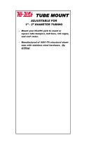
TUNED PIPE MOUNT
6mm plywood former 1 Front tuned pipe mount
6mm plywood former 1 Front tuned pipe mount
Plywood half former 1 Rear tuned pipe mount
4-40 x 1/2-inch socket head cap screw 2 Rear tuned pipe mount
#4 flat washer 2 Rear tuned pipe mount
24-inch medium silicone tubing 2 Tuned pipe mount
1-inch medium silicone tubing 4 Canister mount
2mm plywood horseshoe former 2 Extra fuel tubing mount
ENGINE
1/4-20 x 11/4-inch socket head cap screw 4 Engine to firewall
1/4-20 blind nut 4 Engine to firewall
1/4-inch lock washer 4 Engine to firewall
5mm aluminum spacers 4 Engine to firewall
4-40 x 1/2-inch socket head screw 3 Ignition to engine box
#4 flat washer 3 Ignition to engine box
THROTTLE
4-40 x 141/4-inch pushrod 1 Choke pushrod
4-40 x 151/2-inch pushrod 1 Throttle pushrod
3mm plywood support former 2 Manual choke pushrod
6mm plywood support former 2 Throttle and choke pushrod
1/4-inch balsa triangle stock 2 Pushrod support
4-40 x 2mm ball link with hardware 2 Throttle and choke
90-degree pushrod keeper 2 Throttle and choke
12-inch (305mm) nylon pushrod housing 2 Throttle and choke
Included Parts Listing

4 Hangar 9 Sukhoi SU-26MM SE
Safety Precautions and Warnings
Read and follow all instructions and safety precautions
before use. Improper use can result in fire, serious injury
and damage to property.
COMPONENTS
Use only with compatible components. Should any
compatibility questions exist please refer to the product
instructions, the component instructions or contact Horizon
Hobby, Inc.
FLIGHT
Fly only in open areas to ensure safety. It is recommended
flying be done at AMA (Academy of Model Aeronautics)
approved flying sites. Consult local ordinances before
choosing a flying location.
PROPELLER
Keep loose items that can get entangled in the propeller
away from the prop, including loose clothing, or other
objects such as pencils and screwdrivers. Especially keep
your hands away from the propeller as injury can occur.
BATTERIES
Notes on Lithium Polymer Batteries
When used improperly, lithium polymer batteries are
significantly more volatile than alkaline or Ni-Cd/Ni-MH
batteries used in RC applications. Always follow the
manufacturer’s instructions when using and disposing of any
batteries. Mishandling of Li-Po batteries can result in fire
causing serious injury and damage.
SMALL PARTS
This kit includes small parts and should not be left
unattended near children as choking and serious injury could
result.
Age Recommendation: Not for children under 14
years. This is not a toy.
1
2
3
4
5
6
14 12
13
11
10 15
15
9
8
7
Replacement items
1. HAN124501 Fuselage with Hatch
2. HAN124502 Left Wing with Aileron
3. HAN124503 Right Wing with Aileron
4. HAN124504 Left Stabilizer with Elevator
5. HAN124505 Right Stabilizer with Elevator
6. HAN124506 Rudder
7. HAN124507 Cockpit Hatch without Canopy
8. HAN124508 Canopy
9. HAN124509 Cowl
10. HAN124510 Landing Gear without wheels
11. HAN124511 Wheel Pants
12. HAN124512 Pilot Figure
13. HAN124514 Anodized Wing Tube
14. HAN124515 Anodized Stab Tube
15. HAN308 31/2-inch (90mm) Pro-Lite Wheels
Items not shown
HAN124513 Landing Gear Hatch
HAN124516 Decal Sheet
HAN124517 Hardware Pack
HAN124518 Wood Trays
HAN124519 Painted Cowl Washers
HAN331 Tail Wheel Assembly
HAN4110 2-inch Wing Bolts
Nylon Thumb Screw
HAN321 21/2-inch Wing Bolt
Nylon Thumb Screw
HAN3627 Rudder Hinges
HAN124520 5/32 x 2-inch axles
Contents of Kit and Parts Listing

5Hangar 9 Sukhoi SU-26MM SE
Safe Operating Recommendations
• Inspectyourmodelbeforeeveryflighttomake
certain it is airworthy.
• Beawareofanyotherradiofrequencyuserwhomay
present an interference problem.
• Alwaysbecourteousandrespectfulofotherusersof
your selected flight area.
• Chooseanareaclearofobstaclesandlargeenough
to safely accommodate your flying activity.
• Makecertainthisareaisclearoffriendsand
spectators prior to launching your aircraft.
• Beawareofotheractivitiesinthevicinityofyour
flight path that could cause potential conflict.
• Carefullyplanyourflightpathpriortolaunch.
• AbidebyanyandallestablishedAMANationalModel
Aircraft Safety Code.
Important Information
Regarding Warranty
Please read our Warranty and Liability Limitations section on
page 59 before building this product. If you as the purchaser
or user are not prepared to accept the liability associated
with the use of this Product, you are advised to return this
Product immediately in new and unused condition to the
place of purchase.
Using the Manual
This manual is divided into sections to help make assembly
easier to understand, and to provide breaks between each
major section. In addition, check boxes have been placed
next to each step to keep track of each step completed.
Steps with a single box () are performed once, while
steps with two boxes () indicate the step will require
repeating, such as for a right or left wing panel, two servos,
etc. Remember to take your time and follow the directions.
UltraCote® Covering Colors
White HANU870
Orange HANU877
Pearl Purple HANU847
Silver HANU881
Black HANU874
Recommended Evolution Engine
Evolution® 80GX EVOE80GX
Spinner 41/4-inch 2-blade, predrilled TRU4252BMEV
Spinner 41/4-inch 3-blade, predrilled TRU4253BMEVL
Propeller, 26C (VESS) VSS2603
Propeller, 27 x 10TH (Mejzlik) (optional)
Muffler, Inverted, with Smoke 80GX EVO30073400
JR Chargeswitch JRPA004
DA 85 Engine
Spinner 41/4-inch 2-blade, predrilled TRU4252BMEV
Spinner 41/4-inch 3-blade, predrilled TRU4253BMEVL
Propeller, 26C (VESS) VSS2603
Propeller, 27 x 10TH (Mejzlik) (optional)
JR Chargeswitch JRPA004
In cowl muffler, Pitts style
MTW header & MTW110 canister
MTW RE-3 tuned pipe and header
Transmitter Requirements
This model requires a minimum of a 4-channel radio to
operate all the functions of your aircraft. We suggest the
following radio systems available through Horizon Hobby or
your local hobby distributor.
Spektrum DX8™ SPM8800
JR® Systems X9503 2.4GHz JRP2930
JR Systems 12X 2.4GHz JRP1200
Radio Equipment Requirements
The following items are recommended when installing the
9-Channel AR9100 receiver (SPMAR9100) in your aircraft:
VR6007 Voltage Regulator 7.5A, 6V (2) SPMVR6007
12-Inch EC3™ Extension with 16AWG (2) SPMEXEC312
7.4V, 2000mAh Li-Po Receiver Pack (3) SPMB2000LP
RF Filter: Ring Style (2) (Throttle, Choke) JRPA029
JR Chargeswitch (ignition) JRPA004
6-inch (152mm) Servo Extension (Regulators) JSP98110
4-Pin Balance Connector Ext. (optional) (3) THP4P10E
Optional Choke Servo
Spektrum Digital Servo SPMSA6000
24-inch Servo Extension JRPA102
Required Tools
1/4-inch ratchet drive Covering iron
Cut-off wheel Dish washing liquid
Drill Felt-tipped pen
Flat file Hobby scissor
Light machine oil Medium sandpaper
Mixing cup Mixing sticks
Paper towels Phillips screwdriver: #1
Pin vise Plastic squeegee
Pliers Razor saw
Rotary tool Rubbing alcohol
Ruler Sanding drum
Scissors Side cutters
Silicone adhesive Spray bottle with water
Tape or spray adhesive Trim seal tool
11/32-inch socket, 1/4-inch drive
3-inch (76mm) drive extension, 1/4-inch drive
Adjustable wrench or linkage tool
Drill bit: 5/64-inch (2mm), 3/32-inch (2.5mm),
5/16-inch (8mm)
Hex wrench: 1.5mm, 3/32-inch, 2.5mm, 5/64-inch,
1/8-inch, 3mm, 3/16-inch
Hobby knife with #11 blade
Open end wrench: 10mm, 13mm

6 Hangar 9 Sukhoi SU-26MM SE
Required Adhesives
Thin CA (PAAPT08)
Medium CA (PAAPT02)
Threadlock (PAAPT42)
5-minute Epoxy, 8 oz (PAAPT38)
30-Minute Epoxy, 8 oz (PAAPT39)
Formula 560Canopy Glue (PAAPT56)
Field Equipment Required
Ultra Fuel Pump Glow/Gas HAN155
CM-6 Spark Plug EVO30013309
Evolution 2-cycle oil EVOX1001Q
Optional Field Equipment
Self-stick weights, 6 oz (HAN3626)
Cleaner and towels
Before Starting Assembly
Before beginning the assembly of your model, remove
each part from its bag for inspection. Closely inspect the
fuselage, wing panels, rudder and stabilizer for damage. If
you find any damaged or missing parts, contact the place of
purchase.
If you find any wrinkles in the covering, use a heat gun or
covering iron to remove them. Use caution while working
around areas where the colors overlap to prevent separating
the colors.
HAN100 – Heat Gun
HAN150 – Covering Glove
HAN101 – Sealing Iron
HAN141 – Sealing Iron Sock
Receiver Installation
Required Parts
Fuselage Choke servo (optional)
RF filter coil Receiver with accessories
Hook and loop tape (not included)
1/4-inch (6mm) foam rubber (not included)
24-inch servo extension (optional)
Required Tools and Adhesives
Scissors Phillips screwdriver: #1
Hex wrench: 5/64-inch
Thin CA (for choke servo mounting holes
Hobby knife with #11 blade
1. Remove the four screws securing the canopy hatch
to the fuselage using a 5/64-inch hex wrench. Set
the hatch and screws aside until they are required for
installation.
2. Use a #1 Phillips screwdriver to remove the servo
horn from the throttle servo.
3. Use scissors to cut the tie wraps on the throttle lead
to allow room to install the RF filter coil. Install the RF
filter coil on the lead for the throttle servo to prevent
feedback from the servo getting to the receiver. The
lead will wrap through the coil three times for correct
installation. Install the RF filter coil as close to the
receiver as possible to be the most effective.
4. Plug the extensions in the receiver. Note the tags
on the extensions so they can be plugged into the
correct ports of the receiver.
Hint: Plug the 6-inch (152mm) extension (included with
the AR9100 receiver) in the bind/data port. This will be
routed to the outside of the fuselage to allow binding of the
receiver and flight log data to be accessed without the need
to remove the receiver from the airframe.

7Hangar 9 Sukhoi SU-26MM SE
5. Use the hook and loop strap to secure the receiver
in position. Make sure to use foam to isolate the
receiver from the airframe.
Note: Use a small piece of fuel tubing on the receiver
antenna to keep them straight and to isolate them from the
airframe.
6. Use hook and loop tape to attach the remote
receivers in the fuselage as shown. Make sure to
route the leads for the receivers away from servo
leads and battery leads. Holes have been laser cut
to route the leads through the formers. Note the
direction of the antenna on each receiver. This is done
for the best reception from your radio system.
7. Pass a male/male charge lead into a charge jack
mount. Use a hobby knife with a #11 blade to remove
the covering in the side of the fuselage. Use the
hardware included with the jack to mount the charge
jack mount on the side of the fuselage. Connect the
previously installed 6-inch (152mm) extension lead
from the bind/data port to the male/male lead.
8. (Optional) Install the choke servo as shown using
the hardware provided with the servo. Use a 24-inch
(610mm) servo extension to connect the servo lead
to the receiver. Make sure to secure the servo lead
using string or a commercially available connector
to the extension so it does not unplug inside the
fuselage. Make sure to apply 2–3 drops on thin CA in
each of the screw holes before installing the screws
to harden the surrounding wood.
Note: Install an RF filter coil on the lead for the choke servo
to prevent feedback from the servo getting to the receiver.
The lead will wrap through the coil three times for correct
installation. Install the RF filter coil as close to the receiver
as possible to be the most effective.

8 Hangar 9 Sukhoi SU-26MM SE
Battery and Regulator Installation -
3D Flight
Required Parts
Fuselage Hook and loop strap (2)
12-inch EC3 extension (2) Tie-wraps
Battery (2) Side mount plates (2)
1/4-inch (6mm) foam rubber (not included)
Regulator with accessories (2)
#4 x 1/2 sheet metal screws (8) (not included)
6-inch (152mm) servo extension (2)
Required Tools and Adhesives
5-minute epoxy Scissors
Pin vise Drill bit: 5/64 inch (2mm)
Mixing cups Mixing sticks
Phillips screwdriver: #1 Paper towels
Hobby knife with #11 blade
We have tested two different locations for the receiver
battery and regulator positions inside the fuselage. The
following covers the installation of these components that
are best suited for an aft CG and 3D flight.
1. Use a hobby knife with a #11 blade to remove
the covering on the fuselage for the two regulator
switches on the right and left sides of the fuselage.
Mount the switches using a #1 Phillips screwdriver
and the hardware provided with the switches.
2. Use a hobby knife with a #11 blade to remove the
covering on the fuselage for the charge jacks on the
right and left sides of the fuselage. Install charge
jacks in the larger cutouts below the switches.
3. Connect a 6-inch (152mm) servo extension to the
regulator for the connection to the regulator switch.
4. Repeat steps 1 through 3 to install a second switch
and charge jack on the opposite side of the fuselage.
Prepare the second regulator for installation at this
time as well.
5. Secure the regulators in the fuselage next to the
receiver. Use four #4 x 1/2-inch sheet metal screws
(not included) and four #4 washers (not included)
to secure each regulator. Make sure the regulators
are far enough back that they won’t interfere with
the installation of the canopy hatch. Plug the
regulators into the leads from the receiver, then
route the remaining lead and servo extension from
the regulators through the larger hole in the receiver
floor, keeping the remote receiver leads separated
from the power and servo wires.
6. Locate the side mount plates. Note that the tabs on
one side are longer than those on the opposite side.
The longer tabs will face down into the fuselage when
the plates are installed.

9Hangar 9 Sukhoi SU-26MM SE
Note: Use the 4-pin balance connection (THP4P10E) on
the receiver Li-Po batteries to make it easier to connect the
charger. The receiver extension can be used on the charger
balance lead for this purpose.
7. Wrap a piece of foam rubber around the receiver
battery. Use a hook and loop strap to secure the
receiver battery to the side mount plate. Note the
direction of the leads: they will face to the rear of
the fuselage. Prepare a right and left battery for
installation at this time.
8. Attach the side mount plate in the fuselage using
5-minute epoxy. The tabs on the plate will key into
the fuselage sides as shown. Install both the left and
right plates at this time. Insert the extension into the
jack on the side of the fuselage installed below the
switch so the voltage of the battery can be checked
without the need to remove the canopy hatch.
9. Connect the switch for the regulator to the 6-inch
(152mm) extension from the regulator. Connect a
12-inch (305mm) EC3 extension to the power lead
from the regulator and to the receiver battery. Route
the lead through the openings in the formers. Use tie
wraps to secure the leads inside the fuselage so they
don’t move during flight. Make sure the lead for the
receiver is routed away from the power leads to avoid
radio interference.
Notice: When storing your model, make sure to unplug
the batteries from the regulators as the regulators draw a
small amount of power even when in the off position. If left
connected, they will drain the battery and leave it unusable.
10. Repeat steps 6 through 9 to install the second
receiver battery and regulator in the fuselage. Make
sure to route and secure the power leads in the
fuselage so they are away from the servo and receiver
leads.
Battery and Regulator Installation -
Precision Aerobatics
Required Parts
Fuselage Hook and loop strap (2)
12-inch EC3 extension (2) Tie-wraps
Battery (2) Side mount plates (2)
1/4-inch (6mm) Foam rubber (not included)
Battery Mount Plate (2)
Regulators with accessories (2)
#4 x 1/2-inch sheet metal screws (8) (not included)
#4 washers (8) (not included)
6-inch (152mm) servo extension (2)
Required Tools and Adhesives
5-minute epoxy Scissors
Mixing cups Mixing sticks
Paper towels Thin CA
Hobby knife with #11 blade
We have tested two different locations for the receiver
battery and regulator positions inside the fuselage. The
following covers the installation of these components that
are best suited for a forward CG for precision aerobatics.
1. Use a hobby knife with a #11 blade to remove
the covering on the fuselage for the two regulator
switches on the right and left sides of the fuselage.
Mount the switches using the hardware provided with
the switches.

10 Hangar 9 Sukhoi SU-26MM SE
2. Use a hobby knife with a #11 blade to remove the
covering on the fuselage for the charge jacks on the
right and left sides of the fuselage. Install charge
jacks in the larger cutouts below the switches.
3. Locate the side mount plates. The tabs on one
side are longer than those on the opposite side. The
longer tabs will face down into the fuselage when the
plates are installed.
4. Apply 2–3 drops of thin CA in each of the mounting
holes to harden the surrounding wood. This will keep
the screws from backing out in flight.
5. Attach the regulator to the side mount plate using
four #4 x 1/2-inch sheet metal screws (not included)
and four #4 washers (not included).
6. Repeat Steps 1 through 5 to prepare the second
regulator for installation. Make sure to construct a
regulator for the right and left side of the fuselage.
7. Connect the switch lead to the regulator. Attach
the side mount plate in the fuselage using 5-minute
epoxy. Note that the lead on the regulator for the
battery input will face to the front of the fuselage.
The tabs on the plate will key into the fuselage sides
as shown. Install both the left and right plates at this
time.

11Hangar 9 Sukhoi SU-26MM SE
8. Connect the regulator to the receiver using a
12-inch (305mm) EC3 extension. Route the lead
through the openings in the formers. Use tie wraps to
secure the lead inside the fuselage so it doesn’t move
during flight. Make sure the lead for the receiver is
routed away from the power leads to avoid radio
interference.
Important: Keep the power leads to the receiver remote
antenna leads separated to avoid interference.
9. Connect a 6-inch (152mm) servo extension to the
lead on the battery. Wrap the battery using foam
rubber. Use a hook and loop strap to secure the
receiver battery to the battery mount plate.
10. Use 5-minute epoxy to secure the battery mount
plate in the fuselage next to the fuel tank and behind
the servo as shown. Once the epoxy cures, connect
the lead from the battery to the regulator. Use tie
wraps to secure the leads so they don’t move in the
fuselage during flight.
11. Repeat Steps 7 through 10 to install the remaining
battery and regulator on the opposite side of the
fuselage.
Notice: When storing your model, make sure to unplug
the batteries from the regulators as the regulators draw a
small amount of power even when in the off position. If left
connected, they will drain the battery and leave it unusable.
Engine Installation (Evolution 80GX)
Required Parts
Fuselage assembly 90-degree snap link (2)
1/4-inch lock washer (4) 1/4-20 blind nut (4)
Pushrod support (2) Balsa triangle stock (2)
Engine Muffler
Spinner Propeller
Ignition switch Ignition battery
#4 washer (3) Hook and loop strap
Tie wraps Fuel line
5mm aluminum engine standoffs
Choke pushrod wire, 141/4-inch (362mm)
4-40 x 1/2 socket head bolt (3)
2mm x 4-40 ball end with hardware (2)
Throttle pushrod wire, 151/2-inch (394mm) (2)
1/4-20 x 3/4-inch socket head bolt (4)
Manual choke wire support (2)
(one extra included with kit)
Nylon pushrod housing 12-inch (305mm) (2)
(if using a choke servo)
Required Tools and Adhesives
Threadlock Drill
Pin vise Felt-tipped pen
Hobby knife Pliers
Rotary tool Sanding drum
Cut-off wheel Razor saw
Medium sandpaper Side cutters
Silicone adhesive Ruler
Hobby scissors Canopy glue
Rotary tool with sanding drum
Hex wrench: 1.5mm, 3/32-inch, 5/64-inch, 3/16-inch
Phillips screwdriver: #1 Medium CA
Drill bit: 3/32-inch (2.5mm), 5/16-inch (8mm)
The laser etched markings on the firewall are used for
the installation of the Evolution 80GX. If you are using a
different engine, you will need to use the template included
with your engine for locating any mounting holes and
openings.

12 Hangar 9 Sukhoi SU-26MM SE
Important: The fuel vent line has been wrapped up and
back around the tank to stop the fuel tank from siphoning
fuel during flight.
1. Use a drill and 5/16-inch drill bit to drill the four
mounting holes for the engine mounting bolts.
2. Use a razor saw and rotary tool with a sanding drum
to remove the material from the firewall for the
carburetor.
3. Lightly sand the outside of the 12-inch (305mm)
clear pushrod tube. Insert the tube through the hole
in the sub-firewall and direct it toward the throttle
servo. Position the tube so 2 inches (52mm) of the
tube extends forward of the sub-firewall. If you have
installed the choke servo, install the second tube at
this time as well.
Note: The pushrod tubes may need to be relocated slightly
depending on the style of carburetor on your engine. It is
best not to glue the pushrod tube at this time.
4. Use side cutters to trim the throttle (and choke)
pushrod tubes at the front edge of the servos.
5. Install the 1/4-20 blind nut in the backside of the
firewall. Use a 1/4-20 x 3/4-inch socket head bolt
and 1/4-inch washer to draw the prongs of the blind
nut into the firewall. Use a 3/16-inch hex wrench
to tighten the bolts, drawing the blind nuts into the
firewall. Install all four blind nuts at this time.

13Hangar 9 Sukhoi SU-26MM SE
Note: It may be necessary to rotate the choke lever
depending on how the choke will be operated. Make sure
the position of the lever is such that the linkage can operate
the lever from the open to closed positions.
6. Thread a ball link on the 4-40 x 151/2-inch and 4-40
x 141/4-inch threaded rods. Attach the ball link from
the 4-40 x 151/2-inch threaded rod to the throttle arm
of the carburetor. Attach the ball link from the 4-40 x
141/4-inch threaded rod the choke lever.
Optional: We recommended installing a piece of tubing to
the atmosphere vent on the carburetor. Routing the tubing
into the fuselage to help avoid any pressure differences that
may cause the engine to stumble when transitioning from lo
to hi throttle.
Refer to the engine instruction manual for carburetor
adjustment and fuel line installation.
Note: Always use threadlock on metal-to-metal fasteners.
7. Slide the engine into position on the firewall. The
throttle (and choke) pushrod will slide into the
appropriate guide tube. Use four 3/16-inch (5mm)
spacers, four 1/4-20 x 11/2-inch socket head bolts,
four 1/4-inch lock washers and four 1/4-20 blind
nuts to secure the engine to the firewall. The order
of items will be from the front: bolt, lock washer,
engine mount, spacer, firewall, blind nut. Tighten the
bolts, drawing the blind nuts into the backside of the
firewall. Use a 3/16-inch hex wrench to tighten the
socket head bolts.
8. Connect the fuel line from the tank to the carburetor.
9. Use a pin vise and 3/32-inch (2.5mm) drill bit to
enlarge the hole of the servo arm that is 7/16-inch
(11mm) from the center of the servo horn.
10. Attach the servo horn to the throttle servo using
a #1 Phillips screwdriver. With the throttle servo and
carburetor linkage in the closed position, use a felt-
tipped pen to mark the linkage where it crosses the
hole on the servo arm enlarged in the previous step.
11. Use pliers to bend the pushrod wire 90-degrees at
the mark made in the previous step. Use side cutters
to trim the excess wire so it does not interfere with
the operation of the servo.

14 Hangar 9 Sukhoi SU-26MM SE
12. Secure the pushrod wire to the servo arm using
a pushrod connector. Snap the connector on the
pushrod wire to secure. Lightly sand the pushrod
tube using medium sandpaper in the location of the
plywood pushrod support. This will allow the CA to
adhere the tube to the support.
Note: The servo arm may need to be trimmed to prevent it
from hitting the receiver battery if they are mounted on the
tray behind the servo for the precision aerobatic setup.
13. Use medium CA to glue the plywood pushrod
support and the balsa triangle to the inside of the
fuselage. Glue the balsa support between the fuselage
side and pushrod support using medium CA. The
pushrod tube is then glued to the plywood pushrod
support using medium CA.
14. Repeat Steps 9 through 13 to connect the choke
linkage to the choke servo. Note the servo and choke
will be in the open position when connecting the
linkage.
Note: If you attach the module to the engine box using
screws, make sure to use threadlock on the metal-to-metal
fasteners.
15. Mount the ignition module to the side of the fuselage.
You can use a hook and loop strap or using a 3/32-
inch hex wrench, install three 4-40 x 1/2 socket head
bolts with three #4 washers.
16. Make the connections between the engine and
ignition module following the instructions provided
by the engine manufacturer. Secure any leads using
tie-wraps to prevent them from interfering with the
operation of the engine.
17. (Optional Ignition Light) Use a hobby knife and
#11 blade to remove the covering in the side of the
fuselage for the ignition light. Route the lead and LED
through the fuselage and insert the LED in the hole.
Use a small amount of silicone adhesive to glue the
LED in the fuselage.

15Hangar 9 Sukhoi SU-26MM SE
18. Use a hobby knife and #11 blade to remove the
covering for the ignition switch. Mount the switch
using the hardware provided with the switch. Route
the leads from the switch to the front of the fuselage.
19. Use a hook and loop strap to secure the ignition
battery to the top of the engine box. Connect the
leads from the switch to the battery and ignition
module. Secure the leads using tie-wraps so they
don’t interfere with the operation of the engine.
Note: The suggested muffler includes an option for a
smoke system. The installation of the components for a
smoke system is up to the discretion of the modeler and is
not covered in this manual.
Note: Use the 4-pin balance connection (THP4P10E) on the
ignition Li-Po battery to make it easier to hook up a charger.
The extension can be left in place for accessibility. Use wire
ties to route the extension into the radio compartment near
the ignition switch.
20. Attach the muffler to the engine following the
manufacturer’s instructions.
21. (Optional: Manual choke) Slide a plywood choke
pushrod brace over the choke pushrod and glue
the brace to the fuselage using medium CA. Make
a 90-degree bend in the pushrod so it can be easily
operated from underneath the fuselage.
22. Use a 5/64-inch hex wrench to remove the four
cowl mounting screws with the preinstalled painted
washers and silicone tubing from their locations on
the fuselage. Attach the cowling to the fuselage. Use
a 5/64-inch hex wrench to tighten the screws that
secure the cowl to the fuselage. Use a tapered reamer
to make a 1/4-inch (6mm) hole in the side of the cowl
to access the mixture screws on the carburetor.
Note: The distance from the firewall to the front face of the
propeller drive washer is 61/2-inch (165mm).
23. It will be necessary to remove the material from the
cowling to clear the exhaust system and to provide
cooling air to pass over the engine. Use hobby
scissors and a rotary tool with a sanding drum to
trim the cowling. Check the fit of the cowl over the
engine while making small adjustments to the fit of
the cowling.
Note: A small of canopy glue on the threads of the cowl
mounting screws will allow for easy removal, but help
prevent the screws from vibrating loose in flight.

16 Hangar 9 Sukhoi SU-26MM SE
24. Mount the propeller and spinner on the engine. Make
sure to balance the propeller to reduce any vibrations
that may be transmitted to the airframe.
Optional Tuned Pipe Installation
Required Parts
Fuselage assembly Tuned pipe
Tuned pipe header Tuned pipe coupler
Medium silicone tubing #4 washer (2)
4-40 x 1/2-inch socket head screw (2)
Tuned pipe mount, full, small inner diameter (2)
Tuned pipe mount, full, large inner diameter (2)
Tuned pipe mount, half
Required Tools and Adhesives
Covering iron Trim seal tool
Hex wrench: 3/32-inch 30-minute epoxy
Mixing stick Mixing cup
Paper towel Rubbing alcohol
Hobby knife with #11 blade
Note: We have designed the Sukhoi SU-26MM fuselage
to allow for two sections of the fuselage to be removed
for cooling. Our flying model only has the front section
removed. Prepare the fuselage based on the need for your
particular tuned pipe and particular flying situation.
1. Use a hobby knife with a #11 blade to remove the
covering from the bottom of the fuselage to allow
cooling air to pass through for the tuned pipe. Use a
covering iron and trim seal tool to seal the covering
in place on the fuselage. Note: The length of the opening in the bottom of the
fuselage will be determined by your particular pipe
selection. Check the pipe length before opening the bottom
of the fuselage.
2. Pass the clear fuel tubing through the holes in the
full tuned pipe mounts. Check the fit of the mount
on your particular pipe, as there are different sizes
provided to allow the installation of a variety of tuned
pipes. Once the correct mount has been determined,
use 30-minute epoxy to secure the mount in the
fuselage as shown.

17Hangar 9 Sukhoi SU-26MM SE
3. Attach the header to the engine using the hardware
provided with the header or engine.
Note: Before installing the tuned pipe, you will want
to install the landing gear as described in the section
“Installing the Landing Gear” on Page 22.
4. Place the pipe in the fuselage, passing it through the
full tuned pipe mount. Connect the tuned pipe to the
header using a tuned pipe coupler.
Note: Most tuned pipes can be installed from the hatch
opening into the fuse by carefully positioning the inlet side
of the pipe beside the tank during installation. There will be
some tuned pipes that may need to be installed through the
front opening in the fuselage prior to fitting the engine to
the firewall.
5. Pass the clear tubing through the holes in the mount
in the fuselage and through the holes in the half
tuned pipe mount. The half mount will be secured in
the fuselage using two 4-40 x 1/2-inch socket head
screws and two washers. Use a 3/32-inch hex wrench
to tighten the screws. This mount will secure the pipe
in the fuselage.
6. Check the fit of the cowling over the tuned pipe. It
may be necessary to trim the cowling slightly to
provide clearance for the tuned pipe.
Note: A small of canopy glue on the threads of the cowl
mounting screws will allow for easy removal, but help
prevent the screws from vibrating loose in flight.

18 Hangar 9 Sukhoi SU-26MM SE
Engine Installation (DA85)
Required Parts
Fuselage assembly 90-degree snap link
1/4-inch lock washer (4) 1/4-20 blind nut (4)
2mm lock nut
2mm x 10mm socket head screw
2mm x 4-40 ball end with hardware
Pushrod wire, 181/2-inch (470mm)
1/4-20 x 3/4-inch socket head bolt (4)
Required Tools and Adhesives
Threadlock Drill
Pin drill Felt-tipped pen
Tape or spray adhesive Hobby knife
Rotary tool Sanding drum
Cut-off wheel
Drill bit: 3/32-inch (2.5mm), 5/16-inch (8mm)
The fuel vent line has been wrapped up and back around the
tank to stop the fuel tank from siphoning fuel during flight.
1. Secure the template (located on Page 31) for the
DA85 to the firewall using tape or spray adhesive.
Make sure to align the horizontal and vertical center
lines on the template with those on the firewall.
2. Use a drill and 3/32-inch (2.5mm) drill bit to drill the
four locations for mounting the engine.
3. Use the template to remove the area of the firewall to
allow the carburetor to extend into the engine box.
4. Mount the engine to the firewall using four 1/4-20
x 3/4-inch socket head bolts and four 1/4-inch lock
washers. Make sure to use threadlock on the bolts
as well as the lock washers to help keep them from
vibrating loose.
5. Attach the throttle linkage to the carburetor using
a 2mm x 4-40 ball link 2mm x 10mm socket head
screw and 2mm nut.

19Hangar 9 Sukhoi SU-26MM SE
6. Attach the servo horn to the throttle servo. With the
throttle servo and carburetor linkage in the closed
position, use a felt-tipped pen to mark the linkage
where it crosses the hole on the servo arm that is
3/8-inch (9.5mm) from the center of the servo horn.
7. Bend the pushrod wire 90-degrees at the mark made
in the previous step. Use a pin drill and 3/32-inch
(2.5mm) drill bit to enlarge the outer hole of the
servo arm.
8. Secure the pushrod wire to the servo arm using a
pushrod connector. Snap the connector on the
pushrod wire to secure.
Installing the MTW 110 Canister and Header
(Available from Desert Aircraft)
Note: Before installing the canister muffler, you will want
to install the landing gear as described in the section
“Installing the Landing Gear” on Page 22.
A. Use a felt-tipped pen to draw lines vertically that
connect the bottom of the fuselage to the sides of the
opening.
B. Use a rotary tool and cut-off wheel to cut the former
along the lines made in the previous step.
C. Carefully remove the section from the fuselage.

20 Hangar 9 Sukhoi SU-26MM SE
D. Use a hobby knife to trim the covering 1/8-inch
(3mm) away from the edges of the opening. The
excess material will be sealed back into position to
fuel-proof the area and make a clean installation of
the opening.
E. Use a covering iron to seal the edges of the covering
inside the fuselage.
F. Remove the covering from the bottom of the fuselage
and cut the stringers as shown. Repeat Steps D
through F to seal the covering around the opening.
This is necessary to allow cooling air to pass through
the fuselage to cool the canister muffler.
G. Remove the material from the cowling to clear the
exhaust system and to provide cooling air to pass
over the engine. Refer to the photos in the tuned pipe
section regarding mounting the cowling.
Rudder and Tail Wheel Installation
Required Parts
Fuselage assembly Rudder
Rudder hinge wire Tail wheel assembly
Tail wheel steering spring (2)
2.5mm x 18mm socket head sheet metal screw (2)
Required Tools and Adhesives
Thin CA Drill
Hex wrench: 3mm Ruler
Flat file Threadlock
Hex wrench: 2.5mm, 3/32 inch
1. Use a flat file to sharpen one end of the rubber hinge
wire. This will help the wire guide itself through the
hinges. Line the hinges up between the rudder and
fuselage. Insert the rudder hinge wire using a drill.
The wire will insert slightly in the rudder balance
tab so there is clearance for the tail wheel bracket
installed later in this section of the manual. Once
installed, the wire will extend 3/8-inch (9.5mm) below
the bottom of the fuselage.
/