Pilot Communications 50CC Assembly Manual
- Category
- Toys & accessories
- Type
- Assembly Manual

www.pilot
www.pilot-
-rc.com
rc.com
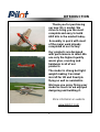
Wingspan: 88 in
Wing area: 1479.8 sp
in
Length: 78.8 in
Engine: 50CC
Assembly Manual For

1
INTRODUCTION
Thank you for purchasing
our new 50 cc model. We
strive to bring you the most
complete and easy to build
ARF kits in the market today.
Assembly is quick with most
of the major work already
completed at our factory.
Our products are designed
with performance in mind. We
use only the highest quality
wood, glue, covering and
hardware in all of our
products.
The model is strong but light
weight making it an ideal
aircraft for 3D and freestyle
flying as well as aerobatics.
We hope you enjoy flying your
model as much as we enjoyed
designing and building it.
More information on website
www.pilot
www.pilot-
-rc.com
rc.com

2
W
WARRANTY
ARRANTY
■All Pilot-RC products are guaranteed against
defects within 30 days of receiving your airplane. This
warranty is limited to construction or production
defects in both material and workmanship. It DOES
NOT cover any components or parts damaged by
misuse or modification.
■The manufacturer can not control the assembly,
operation and maintenance of this product therefore,
Pilot-RC are not responsible for any damage that
occurs as a result of the use or misuse of this
radio controlled model.
■In no circumstance will Pilot-RC accept liability
exceeding the original cost of the airframe. (not
including engine and radio system).
■Shipping costs for ALL returns (regardless of the
reason for return) will be paid by the customer.
Shipping costs for replacement parts will paid by the
customer.

3
ATTENTION
ATTENTION
■You should not regard this plane as toy!
■
To ensure safety, please read the instruction
manual thoroughly before assembly.
■Building and operating a model plane requires
diligent practice and correct guidance. An
inexperienced flyer can cause serious injury and
property damage.
■Seek the assistance of an experienced RC pilot or
model airplane club for help with assembly, operation
and maintenance to ensure your flying experience is
both enjoyable and safe.
■Fly only in AMA (Academy of Model
Aeronautics) approved areas.
Pilot-RC reserves the right to make changes and
amendments to construction manuals, terms and
conditions without notice. If you have any problems and
questions please contact Pilot –RC
Email: pilot-rc@139.com , pilot-rc@hotmail.com
Cellphone:+86 760 88781293
FAX: +86 760 88780293
Address: No.34,ChengnanErRoad , Zhongshan city, 528400, Guangdong
Province, China

4
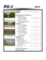
Introduction ………………….………..….…….….
Warranty …………………….……..….…..…….
Attention …………….…………..….……..…….
Landing Gear And Rudder Unit
Rudder Assembly
Rudder Control Horns ………..…….…...……..
Tail Wheel Installation …………..……..........
Rudder Axis Installation …….……...….……..
Landing Gear Assembly .
Main Landing Gear Installation ………….…..…….
Pants Installation …………..….………
Servo Unit
Wing Servo Assembly
Servo Arm Installation ………….….……….
Aileron Control Horns ………….……….…..
Servo Installation …….…………..……
Rudder Servo Assembly
Servo Tray Installation ….…….….......……..
Servo Installation ……….….……...……
Elevator Servo Assembly
Servo Arm Installation ………….…………….
Elevator Control Horns ……………....….….
Servo Installation ……………….....………
Switch Assembly ………….……….....………
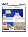
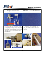
Engine Unit
Firewall Assembly ……….…….....……….
Engine Assembly ……….…..……..……
Throttle Servo Assembly ….….…...…….……
Muffler Assembly
Canister Bracket Installation ……….…....……….
Muffler and Canister ………….…….……….
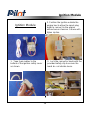
Ignition Module ………….…….……….
Hatch And Fuel Tank ………….….……....……
Cowl Assembly …………………......……
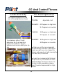
CG And Control Throws …………………………..
Flight Preparation …...…………….….…..……
INDEX
1
2
3
18
19
5
7
9
10
12
13
14
15
22
23
24
27
28
30
32
30
33
34
35
36
38
39

5
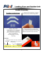
Landing Gear and Rudder Unit
Rudder Assembly
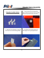
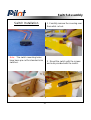
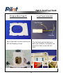
Rudder Control Horn 1. Remove the protective covering
from the horns and locking plates.
Please refer to the
HARDWARE LIST (download
with instructions) to get the
exact information about every
step. A printed list is
recommended for easy
checking.
2. Trace around the locking plate
with a knife and remove the covering
below to expose the pre-cut slots.
Example:
On the step of Rudder Control Horn installation
You can search
Rudder

6
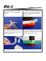
Rudder Assembly
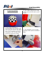
3. Scuff the middle of horns with
sand paper to ensure a good glue
bond.
4. Apply 30 minute epoxy inside
the pre-cut slots and coat the horn
with epoxy as shown
5. Fit the horns into the locking plate
and then insert them into the pre-cut
slots. Wipe away excess glue with
rubbing alcohol.
6. Make sure the horns are correctly
aligned (by installing the linkage bolt)
before the epoxy has cured.

7
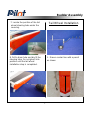
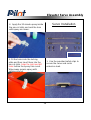
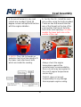
7. Locate the position of the tail
wheel steering tube under the
covering.
8. Drill a 6mm hole and dry fit the
steering tube. Do not glue it into
position until the tail wheel
installation step is completed.
Tail Wheel Installation
Rudder Assembly
1. Draw a center line with a pencil
as shown

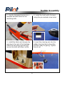
8
2. Use the tail wheel bracket as a
template and drill holes for the
mounting bolts.
3. Install the blind nuts through the
opening in the rear of the fuselage.
Attach the tail wheel bracket and
secure the bolts with Blue Loctite.
4. Install the hatch with 4 screws
using the pre marked screw holes.
5. Insert the steering arm into the
rudder steering tube and position
the tube ready for gluing. Tighten
the set nut
Rudder Assembly

9
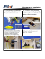
6. Epoxy the steering tube in place
as shown.
Rudder Hinge Installation
1. Insert the hinge pin into the
hinges from the bottom of the
rudder and push it right through to
the top to locate the entry hole.
2. Fit the rudder by aligning the
hinges and inserting the hinge pin
from the top of the rudder.
Rudder Assembly
This demountable rudder
design could offer more room
for you to ship and store

10
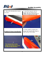
3. Fit the Teflon washer and tighten
the collar set screw with a 1.5mm hex
wrench as shown.
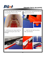
Main Landing Gear Installation
NOTE: the correct edge in mounting
Taper
to rear
Straight
edge to
front of
fuse
Landing Gear Assembly

11
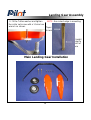
Landing Gear Assembly
1. Install the landing gear in the pre
drilled holes with the supplied bolts
and locking nuts.
Note: Don’t over tighten and crack
the carbon fiber.
2. Install the landing gear axles with
lock nuts but do not tighten yet.
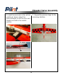
4. Position the flat sides of the axle
bolt vertically to the ground then
tighten the lock nut against the
landing gear strut.
3. Lift the rear of fuselage parallel to
the ground as shown.

12
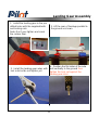
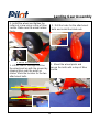
Landing Gear Assembly
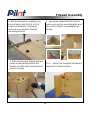
1. Lift the rear of fuselage and line
the wheel pant up with the ground by
slipping them over the axles as
shown. Mark the location for the two
attachment bolts.
2. Drill the holes for the attachment
bolts and install the blind nuts.
3. Mount the wheel pants and
secure the bolts with a drop of Blue
Loctite.
5. Install the wheel and tighten the
collar set screw using a drop of Blue
Loctite. Make sure the wheel rotates
freely.
Pants Installation

13
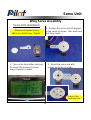
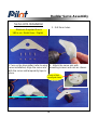
Servo Unit
Wing Servo Assembly
Minimum Required Servo:
Servo Arm Installation
1. Turn on the transmitter and plug
the servo into receiver. Ensure
every channel is neutral.
2. Position the servo arm 90 degrees
to the servo as shown. Then mark and
drill 2mm holes.
3. Mount the servo arm with
screws and nuts as shown.
180 in.oz / Metal Gear / Digital
A drop of fast
cured gulehere

14
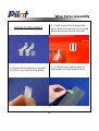
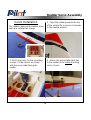
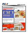
Aileron Control Horns
1. Remove the protective covering
from the horns and locking plates.
2. Trace around the locking plate
with a knife and remove the covering
below to expose the pre-cut slots.
3. Scuff the horns with a piece of
sand paper for a good glue bond.
Wing Servo Assembly

15
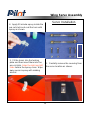
4. Apply 30 minute epoxy inside the
pre-cut slots and coat the horn with
epoxy as shown.
5. Fit the horns into the locking
plate and then insert them into the
pre-cut slots. Align the right and left
sides before the epoxy cures. Wipe
away excess epoxy with rubbing
alcohol
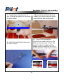
Servo Installation
1. Carefully remove the covering from
the servo location as shown.
Wing Servo Assembly

16
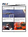
3. Tape the end of the servo
extension lead to the pre installed
pull string.
4. Pull the extension lead through to
the root of the wing.
5. Drill 1mm holes for the servo
mounting screws. Position the servo
with the servo label closest to the
wing trailing edge.
Wing Servo Assembly
2. Use the provided safety clips to
secure the servo and servo extension
leads.

17
6. Install the servo arm facing
toward the wing tip and adjust the
pushrod length to ensure the aileron
and servo are in the neutral position.
7. Repeat all the previous steps for
the other wing
The wing tube and wing bolts will be
mounted in the final assembly.
Wing Servo Assembly

18
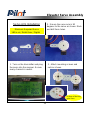
Rudder Servo Assembly
Servo Arm Installation
1.Turn on the transmitter (refer to wing
servo installation) Align the servo arm
with the servo and temporarily tape in
place.
2. Drill 2mm holes.
3. Attach the servo arm with
mounting screws and nuts as shown.
Minimum Required Servo:
180 in.oz / Metal Gear / Digital
A drop of fast
cured gulehere

19
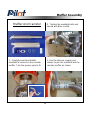
Servo Installation
1. Drill 1mm holes for the mounting
screws. Fit the servos as shown
with the servo label facing the
rudder.
2. Tape the rudder panel to the top
of the vertical fin to ensure it remains
in the neutral position.
The rudder cables and couplers have
been pre installed as shown
3. Attach the pre-installed bolt link
to the rudder horns without locking
nut as shown.
Rudder Servo Assembly
Page is loading ...
Page is loading ...
Page is loading ...
Page is loading ...
Page is loading ...
Page is loading ...
Page is loading ...
Page is loading ...
Page is loading ...
Page is loading ...
Page is loading ...
Page is loading ...
Page is loading ...
Page is loading ...
Page is loading ...
Page is loading ...
Page is loading ...
Page is loading ...
Page is loading ...
Page is loading ...
-
 1
1
-
 2
2
-
 3
3
-
 4
4
-
 5
5
-
 6
6
-
 7
7
-
 8
8
-
 9
9
-
 10
10
-
 11
11
-
 12
12
-
 13
13
-
 14
14
-
 15
15
-
 16
16
-
 17
17
-
 18
18
-
 19
19
-
 20
20
-
 21
21
-
 22
22
-
 23
23
-
 24
24
-
 25
25
-
 26
26
-
 27
27
-
 28
28
-
 29
29
-
 30
30
-
 31
31
-
 32
32
-
 33
33
-
 34
34
-
 35
35
-
 36
36
-
 37
37
-
 38
38
-
 39
39
-
 40
40


Pilot Communications 50CC Assembly Manual
- Category
- Toys & accessories
- Type
- Assembly Manual
Ask a question and I''ll find the answer in the document
Finding information in a document is now easier with AI
Other documents
-
AeroWorks Extra 260 Assembly Manual
-
-
-
-
-
-
-
-
-