Page is loading ...

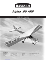
Specications
Wingspan: ..............................................................63 in (1600mm)
Length: ................................................................ 52.5 in (1334mm)
Wing Area: ..................................................710 sq in (45.8 sq dm)
Weight: ....................................................... 5–5.5 lb (2.27–2.49 kg)
Radio: .............................................................4-channel minimum
Engine: ............................ .40–.46 2-stroke (glow), Power 25 (EP)
Alpha 40 ARF
Assembly Manual

2 Hangar 9 Alpha 40 ARF Assembly Manual
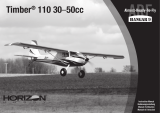
Large Replacement Parts
1. HAN246001 Fuselage with Hatch
2. HAN246002 Wing Set with Wing Tube
3. HAN246003 Tail Set
4. HAN246004 Wing Tube
5. HAN246005 Landing Gear Set with Wheels
6. HAN246006 Engine Nylon Mount
7. HAN246007 Fuel Tank 9 oz
8. HAN246009 Red 2-inch 2-blade Spinner
9. HAN246013 Small Wood Parts
10. HAN246015 Decals
Small Replacement Parts (not shown)
HAN246008 EP 45mm Standoffs
HAN246010 Pushrods
HAN246011 Hardware Package
HAN246012 Nylon Parts Package
HAN246014 Tail Set Wing Nuts
Contents of Kit and Parts Layout
6
9
9
2
24
5
5
5
7
8
10
1
3
Table of Contents
Contents of Kit and Parts Layout ...........................................2
Included Parts Listing ............................................................3
Using the Manual ...................................................................4
UltraCote® Covering Colors ..................................................4
Before Starting Assembly ......................................................4
Radio Systems Requirements ................................................4
Recommended Setup - Glow .................................................4
Recommended Setup - Power 25 ..........................................4
Field Equipment Required ......................................................4
Optional Field Equipment .......................................................4
Tools and Supplies .................................................................4
Additional Required Adhesives ..............................................4
Important Information Regarding Warranty Information .......4
Servo Installation - Fuselage ..................................................5
Glow Engine Installation ........................................................6
Fuel Tank Installation .............................................................8
Muffler Installation ...............................................................10
Propeller and Spinner - Glow Engine Installation ................11
Electric Motor Installation ....................................................12
Propeller and Spinner Installation - Electric Motor ..............17
Landing Gear Installation .....................................................18
Receiver Installation - Electric Motor Option .......................21
Receiver installation - Glow Engine Option ..........................22
Wing Dowel Installation .......................................................24
Fin and Stabilizer Installation ...............................................25
Throttle Linkage Connection ................................................28
Elevator Linkage Installation ................................................30
Rudder and Steering Linkage Installation ............................33
Aileron Servo Installation .....................................................37
Wing Assembly ....................................................................40
Optional: Gluing the Wing Halves ........................................41
Wing Installation ..................................................................43
Checking the Control Surface Movement.............................44
Checking the Throttle Operation ..........................................45
Balancing Your Alpha ARF ...................................................46
Control Throws ....................................................................47
Maintaining Your Model .......................................................48
Flight Preparations ...............................................................48
Safety Do’s and Don’ts for Pilots .........................................49
Daily Flight Checks ...............................................................49
Glossary of Terms ................................................................49
Safety, Precautions and Warnings .......................................50
Warranty Information ...........................................................50
Instructions for Disposal of WEEE by
Users in the European Union .........................................52
2009 Official Academy of Model Aeronautics Safety Code ..52

3Hangar 9 Alpha 40 ARF Assembly Manual
Included Parts Listing
WING
Nylon Clevis (2) Ailerons
Snap link (2) Ailerons
Clear wing center tape 1/2 x 14-inch (1) Seal top center wing joint
White covering 3/4 x 14-inch (1) Seal top center wing joint
Red covering 3/4 x 14-inch (1) Seal bottom center wing joint
RUDDER AND ELEVATOR
3mm x 10mm socket head cap screw (2) Stabilizer to fuselage
#4 silver flat washer (2) Stabilizer to fuselage
#4 silver flat washer (2) Rudder to stabilizer
3mm wing nut (2) Stabilizer to vertical fin
Nylon clevis (2) Rudder and elevator
Snap link (2) Rudder and elevator
LANDING GEAR
Main landing gear assembly (2) Includes 21/2-inch (65mm) wheel
and 4mm wheel collars
Nose gear assembly (1) Includes with 21/2-inch (65mm)
wheel and 4mm wheel collars
#4 x 3/8-inch wood screw (4) Landing gear to fuselage
Landing gear straps (2) Landing gear to fuselage
Nose gear control arm with setscrew (1)
PUSHRODS
33/8 x 1/4-inch hardwood support pieces (2) Fuel tank support
2-56 x 61/8-inch one end threaded pushrod (2) Ailerons
2-56 x 163/4-inch pushrod with Z-bend (1) Nose gear
2-56 x 161/4-inch one end threaded pushrod (1) Throttle
2-56 x 28-inch one end threaded pushrod (2) Elevator and rudder
BAGGED SEPARATELY
Fuselage with hatch (1)
Right wing panel with aileron (1)
Left wing panel with aileron (1)
Vertical fin (1)
Horizontal stabilizer (1)
Aluminum wing tube, 12mm x 318mm (1)
FUSELAGE
9 oz (260cc) fuel tank (assembled) (1)
#4 x 5/8-inch wood screw (1) Tank support tray
3mm x 12mm socket head cap screw (2) Fuselage lower hatch
#4 flat washer (2) Fuselage lower hatch
EZ connector with setscrew (1) Nose gear
#2 flat washer (2) EZ connector spacers
C-Clip (2) Secures EZ connector
43/4 x 1/4-inch dowel rod (2) Wing to fuselage
Rubber band (10) Wing to fuselage
Plywood tank support tray (1) Secures tank in position
Plywood EP battery tray (2) Holds EP battery
Silicone safety clear tubing (2) Clevis keepers
Nylon clevis (1) Throttle
Snap link (1) Throttle
MOTOR MOUNT
8-32 x 3/4-inch socket head cap screw (4) EP motor to EP standoffs
8-32 x 1-inch socket head cap screw (4) Motor mount to firewall/EP
standoffs to firewall
#8 Silver flat washer (4) Motor mount to firewall/EP
standoffs to firewall
4-40 x 1-inch socket head cap screw (4) Engine to motor mount
#4 silver flat washer (4) Engine to motor mount
8-32 blind nut (4) Engine mount
4-40 nylon inserted locknut (4) Engine to motor mount
Black nylon motor mount (2)
45mm EP standoffs (4)
2-inch (50mm) 2-blade spinner, red (1)

4 Hangar 9 Alpha 40 ARF Assembly Manual
Using the Manual
This manual is divided into sections to help make assembly
easier to understand, and to provide breaks between each
major section. In addition, check boxes have been placed
next to each step to keep track of each step completed.
Steps with a single box () are performed once, while
steps with two boxes () indicate the step will require
repeating, such as for a right or left wing panel, two servos,
etc. Remember to take your time and follow the directions.
UltraCote® Covering Colors
• Midnight Blue HANU885
• White HANU870
• True Red HANU866
Before Starting Assembly
Before beginning the assembly of your model, remove
each part from its bag for inspection. Closely inspect the
fuselage, wing panels, rudder and stabilizer for damage.
If you find any damaged or missing parts, contact the
place of purchase.
If you find any wrinkles in the covering, use a heat gun or
covering iron to remove them. Use caution while working
around areas where the colors overlap to prevent separating
the colors.
HAN100 – Heat Gun
HAN150 – Covering Glove
HAN101 – Sealing Iron
HAN141 – Sealing Iron Sock
Radio Systems Requirements
Spektrum™ Radio System (recommended)
• DX6i 6-channel radio or greater with receiver
(SPM6600)
• DS821 Digital Sport Servo (4) (JRPS821)
• 6-inch Servo Extension (JSP98110)
• Receiver Battery, 2300mAh (JRPB5006)
• JR® Switch, Chargeswitch (JRPA004)
Recommended Setup - Glow
• Evolution® Trainer Power System: A (EVOE100)
or
• Evolution .46NX with Muffler (EVOE0461)
• Evolution Propeller 11 x 5 (EVO11050)
• Evolution Propeller, 3-Blade (EVO100P) (optional)
• 3-Blade Spinner, White (EVOE100S) (optional)
• Exhaust Diverter (DUB697) (optional)
Recommended Setup - Power 25
• Power 25 Brushless Outrunner Motor,
870Kv (EFLM4025A)
• 11 x 8e Electric Propeller (APC11080E)
• 60-Amp Lite Switch-Mode BEC Brushless (EFLA1060)
• 3200mAh 4S 14.8V 20C Li-Po,
13AWG EC3 (EFLB32004S)
Field Equipment Required
• Fuel (15% recommended)
• Propeller
• Long Reach Glow Plug Wrench (HAN2510)
• Metered Glow Driver with Ni-Cd & Charger (HAN7101)
• 2-Cycle Sport Plug (EVOGP1)
• Manual Fuel Pump (HAN118)
Optional Field Equipment
• Selfstick Weights, 6 oz (HAN3626)
• PowerPro™ 12V Starter (HAN161)
• 12V 7Ah Sealed Battery (HAN102)
• Power Panel (HAN106)
• Blue Block After Run Oil (EVOX1001)
• Cleaner and towels
Tools and Supplies
Drill Epoxy brush
Felt-tipped pen Hook and loop tape
Hobby knife with #11 blade Low-tack tape
Sandpaper Mixing cup
Mixing stick Paper towel
Phillips screwdriver: #1, #2 Pencil
Pin vise Pliers
Ruler Diagonal cutters
Rubbing alcohol Felt-tipped pen
Threadlock Hook and loop tape
Hook and loop strap
Foam rubber, 1/4-inch (6mm)
Nut driver or box wrench: 1/4-inch
Box wrench to fit propeller nut
Box end or open end wrench: 10mm (2)
Hex wrench or ball driver: 1.5mm, 2.5mm, 3/32-inch,
9/64-inch
Drill bit: 1/16-inch (1.5mm), 5/64-inch (2mm), 1/8-inch
(3mm), 5/32-inch (4mm), 11/64-inch (4.5mm)
Additional Required Adhesives
30-Minute Epoxy (HAN8002)
Medium CA (PAAPT02)
Thin CA (PAAPT08)
Important Information
Regarding Warranty Information
Please read our Warranty and Liability Limitations section on
Page 50 before building this product. If you as the purchaser
or user are not prepared to accept the liability associated
with the use of this Product, you are advised to return this
Product immediately in new and unused condition to the
place of purchase.
The Spektrum trademark is used with permission
of Bachmann Industries, Inc.

5Hangar 9 Alpha 40 ARF Assembly Manual
Servo Installation-Fuselage
Required Parts
Fuselage Servo with hardware (4)
Receiver Receiver battery
Switch harness
6-inch (152mm) servo extension
Required Tools and Adhesives
Phillips screwdriver: #1 Thin CA
Step 1
Locate the necessary items for your radio system. Plug the
servos and switch harness in the receiver. Plug a battery into
the switch harness. Check that all the servos work properly.
Note: You may need to bind your radio system if you
are using a 2.4GHz system. Follow the instructions
provided with your radio system to do so.
Note: Make sure to turn off both the transmitter and
receiver before unplugging the servos.
Important: You will need to connect a 6-inch (152mm)
extension in the Aileron port of the receiver to connect
to the servo used for the Ailerons. Leave the extension
plugged into the receiver when unplugging the servos.
Step 2
Prepare the servos by installing the rubber grommets and
brass eyelets in the servos. Note that the eyelets are inserted
from the bottom of the servo.
Step 3
Use a #1 Phillips screwdriver to thread a servo mounting
screw into the holes in the servo tray inside the fuselage.
Apply 2–3 drops of thin CA in the holes to harden the
surrounding wood. This makes the screws more secure and
less likely to vibrate loose.

6 Hangar 9 Alpha 40 ARF Assembly Manual
Step 4
Mount the rudder and elevator servos in the fuselage using
the screws provided with the servos. Use a #1 Phillips
screwdriver to tighten the screws. Note the direction of the
servos in the photo.
Step 5
If you are installing a glow engine, you will need to install the
servo used to control the throttle at this time.
Glow Engine Installation
Required Parts
Fuselage assembly Engine mount rail (2)
#8 washer (4) #4 washer (4)
8-32 blind nut (4) 4-40 locknut (4)
Safety tubing Clevis
2-56 x 161/4-inch throttle pushrod
4-40 x 1-inch socket head screw (4)
8-32 x 1-inch socket head screw (4)
Required Tools and Adhesives
Nut driver: 1/4-inch Threadlock
Hex wrench or ball driver: 3/32-inch, 9/64-inch
Step 1
Locate the necessary hardware to install the engine on
your model.
Step 2
Slide a #8 washer on an 8-32 x 1-inch socket head screw.
Slide the screw into the engine mount rail as shown. You will
be using four screws, four washers and two engine mount
rails in this step to prepare the right and left engine mount
rails. Place a drop of threadlock on the threads of each bolt.
Threadlock will prevent the bolts from vibrating loose in flight.
Step 3
Position an engine mount rail on the fuselage. Thread an
8-32 blind nut on the screw. Note that the prongs on the
blind nut will go into the backside of the firewall to keep
them from rotating. The nuts are not to be tightened at this
time so the mount can be positioned for your engine. The
bolts wil be tightened once the engine has been secured to
the mounting rails.

7Hangar 9 Alpha 40 ARF Assembly Manual
Step 4
Place a #4 washer on each of the four 4-40 x 1-inch socket
head bolts. Slide the screws through the holes in the engine
mount flange.
Step 5
Place the engine on the mounting rails. The screws will go
through the holes in the rails. Thread a 4-40 locknut on each
screw. The nuts are only finger-tight at this time.
Step 6
Use a 9/64-inch hex wrench or ball driver to tighten the
screws that attach the mount to the firewall. Make sure the
blind nuts are drawn into the back of the firewall. Also make
sure you have placed a small amount of threadlock on each
of the screws so they don’t vibrate loose in flight.
Step 7
Use a 3/32-inch hex wrench or ball driver and a 1/4-inch
nut driver to tighten the hardware securing the engine to the
engine mounting rails.

8 Hangar 9 Alpha 40 ARF Assembly Manual
Step 8
Use a hobby knife to cut a 1/4-inch (6mm) piece of tubing
from the 2-inch (52mm) safety tubing.
Step 9
Slide the piece cut in the previous step on a nylon clevis.
Thread the clevis 10-turns onto the threaded end of the 2-56
x 161/4-inch throttle pushrod wire.
Step 10
Slide the pushrod wire into the tube in the firewall that aligns
with the carburetor arm. Connect the clevis to the carburetor
arm and slide the tubing over the forks of the clevis to keep
the clevis from opening accidentally.
Fuel Tank Installation
Required Parts
Fuselage Fuel tank brace, front
Fuel tank brace, rear 3mm washer (2)
Fuselage hatch Fuel tank (assembled)
3mm x 12mm socket head scew (2)
Required Tools and Adhesives
Threadlock Scissors
Hobby knife with #11 blade Phillips screwdriver: #2
Hex wrench or ball driver: 2.5mm
Step 1
Locate the items necessary to install the fuel tank in the fuselage.

9Hangar 9 Alpha 40 ARF Assembly Manual
Step 2
Inspect the fuel tank to determine the internal positioning
of the vent line. This is important as the vent line must face
to the top of the fuselage for the engine to run properly.
You may want to place a piece of tape on the tube that
corresponds to the vent line for easier identification later.
Clunk
Vent Line
Top View
Side View
Vent Line (faces top of fuselage)
To Muffler
To Carburetor
Step 3
Insert the fuel tank in the fuselage. Guide the fuel lines
through the hole in the firewall.
Step 4
Guiding the fuel tubes to the top of the fuselage, place the tank
in the fuselage so it rests in the fuselage as shown. The tank
will fit snug against the back of the firewall when installed.
Step 5
Locate the fuel tank braces. The rectangular piece is the rear
brace, while the shaped one is the front brace.
Step 6
Test fit the braces in the fuselage. They will lock into the
sides of the fuselage when installed properly. Once fit, use
medium CA to glue the braces to the fuselage sides.

10 Hangar 9 Alpha 40 ARF Assembly Manual
Step 7
Use a hobby knife with a #11 blade to expose the two holes
for the fuselage hatch mounting screws.
Step 8
Slide the fuselage hatch in position on the fuselage. The tabs
will lock the front of the hatch in position.
Step 9
Slide a #4 washer on a 3mm x 12mm socket head screw.
Place a drop of threadlock on the screw.
Step 10
Use a 2.5mm hex wrench or ball driver to tighten the
screw. Use two screws and washers to secure the hatch
to the fuselage.
Muffler Installation
Required Parts
Fuselage Muffler
Required Tools and Adhesives
Hobby knife with #11 blade Hex wrench to fit muffler
Step 1
Attach the muffler to the engine using the hardware
provided with the engine. Make sure to follow the engine
manufacturer’s instructions where applicable.
Step 2
Connect the fuel lines to the carburetor and muffler. The line
from the vent will attach to the muffler, while the line from the
clunk will attach to the carburetor. Use scissors or a hobby
knife and #11 blade to trim the length of the line if necessary
so they don’t interfere with the operation of the engine.

11Hangar 9 Alpha 40 ARF Assembly Manual
Propeller and Spinner - Glow Engine
Installation
Required Parts
Fuselage assembly Spinner assembly
Propeller
Required Tools and Adhesives
Open end or box wrench: 3/8-inch
Phillips screwdriver: #1
Step 1
Locate the items necessary to install the spinner on your engine.
Step 2
Check that the flywheel is fully installed on the engine. It fits
closely to the engine when positioned correctly. Slide the
spinner backplate onto the engine crankshaft so it is tight
against the flywheel.
Step 3
Slide the propeller onto the engine crankshaft. The blades
of the propeller will be positioned against the bosses for the
spinner screws of the spinner backplate as shown below.
Step 4
Slide the propeller washer onto the engine crankshaft.
Step 5
Thread the propeller nut onto the engine crankshaft.
Step 6
Use an adjustable wrench to tighten the propeller nut. Secure
the propeller and spinner backplate onto the engine crankshaft.
Important: When tightening the propeller nut, always
use an adjustable wrench, box end wrench or 3/8-inch
drive socket. Using pliers will not allow you to place
enough grip to properly tighten the propeller nut.
Note: Make sure the propeller has not moved from
its position as described back in Step 3. If it has, the
spinner cone will not be able to be installed in the
following steps.

12 Hangar 9 Alpha 40 ARF Assembly Manual
Step 7
Slide the spinner cone over the propeller. It will fit into the
grooves in the spinner backplate when installed.
Step 8
Use the two 3mm x 10mm sheet metal screws supplied
with the spinner to secure the spinner cone to the spinner
backplate. A #1 Phillips screwdriver will be required to
tighten the screws.
Electric Motor Installation
Required Parts
Fuselage 45mm Motor standoff (4)
#8 washer (4) Battery tray (2)
Fuselage hatch 3mm washer (2)
Motor battery
Electric motor with mount and hardware
Electronic speed control (ESC)
Hook and loop strap (not included)
Hook and loop tape (not included)
3mm x 12mm socket head screw (2)
Motor with mounting hardware
8-32 x 1-inch socket head screw (4)
8-32 x 3/4-inch socket head screw (4)
Required Tools and Adhesives
30-minute epoxy Mixing stick
Threadlock Drill
Open end wrench: 5/16-inch Phillips screwdriver: #1
Drill bit: 11/64-inch (4.5mm)
Hex wrench of ball driver: 9/64-inch, 2.5mm
Step 1
Locate the parts necessary to install the electric motor
on the fuselage.
Step 2
Slide a #8 washer on a 8-32 x 1-inch socket head screw.
Insert the screw through the appropriate hole in the firewall
from the inside of the fuselage.

13Hangar 9 Alpha 40 ARF Assembly Manual
Step 3
Prepare three more 8-32 x 1-inch socket head screws and
insert them into the firewall as shown.
Step 4
Place a drop of threadlock on each of the screws.
Step 5
Thread a 45mm EP standoff on each of the screws. Use
a 9/64-inch hex wrench or ball driver to tighten the 8-32
socket head screws while holding the standoff with a 5/16-
inch open end wrench. Install all four standoffs at this time.
Step 6
Use a drill and 11/64-inch (4.5mm) drill bit to enlarge the
mounting holes in the X-mount. It is highly recommended
to use a drill press as the X-mount can easily be pulled from
your hand if using a hand drill.
Step 7
Apply a drop of threadlock on each of the screws used
to attach the X-mount to the motor. Use a #1 Phillips
screwdriver to secure the mount to the motor.

14 Hangar 9 Alpha 40 ARF Assembly Manual
Step 8
Use four 8-32 x 3/4-inch socket head screws to attach
the motor to the motor standoffs. Remember to use
threadlock on the screws so they don’t vibrate loose. The
wires from the motor will go into the fuselage through the
large hole in the firewall.
Step 9
Prepare the speed control with the necessary connectors
to connect it to your choice of battery and motor. Follow
the instructions provided with the speed control to
complete this step.
Step 10
Place a piece of hook and loop tape on the bottom of the
speed control. Leave the backing on the mating piece of tape
until instructed to remove.
Step 11
Connect the leads from the motor to the speed control. If
you are using E-flite components, the colors will match
from the speed control and motor. If you are using other
components you may need to change the motor wires later
when checking the operation of the motor.
Step 12
Use a hobby knife to remove the covering from the opening
in the side of the fuselage for the speed control switch. Use
the hardware provided with the speed control to mount the
switch in the side of the fuselage.
Step 13
Position the speed control in the fuselage as shown. It will
be secured once the battery trays have been installed.

15Hangar 9 Alpha 40 ARF Assembly Manual
Step 14
Pass a hook and loop strap (not included) through the slots
in the two battery trays as shown.
Step 15
Insert the first battery tray by angling it in the fuselage as
shown. The tray will then fit into the fuselage where it can be
slid toward the rear of the fuselage.
Step 16
The second tray goes in the same as the first, but is
positioned to the front of the fuselage.
Step 17
Once both trays are in the fuselage, use a small amount
of 30-minute epoxy to glue the trays to the sides of the
fuselage. Make sure they are secure so the weight of the
battery does not cause them to come loose.

16 Hangar 9 Alpha 40 ARF Assembly Manual
Step 18
The next step is to remove the backing from the hook and loop
material from the speed control and secure it to the battery
trays. This is tricky and will require patience to accomplish.
Step 19
Use the hook and loop straps to secure the motor battery
in the fuselage. If the battery slides forward or aft in the
fuselage, use a small piece of hook and loop tape between
the tray and battery to prevent it from doing so.
Step 20
Use a hobby knife with a #11 blade to expose the two holes
for the fuselage hatch mounting screws.
Step 21
Slide the fuselage hatch in position on the fuselage. The
tabs will lock the front of the hatch in position. Slide a #4
washer on a 3mm x 12mm socket head screw. Place a drop
of threadlock on the screw. Use a 2.5mm hex wrench or ball
driver to tighten the screw. Use two screws and washers to
secure the hatch to the fuselage.
Step 22
On the bottom of the fuselage, right behind the rear window,
is an area that can be removed to provide cooling air to pass
through the fuselage to cool the motor battery. Removing
this covering is only necessary if you are not using the
newer Li-Po batteries capable of a 25C discharge rate.

17Hangar 9 Alpha 40 ARF Assembly Manual
Propeller and Spinner Installation-
Electric Motor
Required Parts
Fuselage assembly Spinner assembly
Propeller Propeller adapter
Required Tools and Adhesives
Phillips screwdriver: #1
Hex wrench or ball driver: 3/32-inch (2mm)
Step 1
Locate the items necessary to install the propeller and
spinner on the motor.
Step 2
Slide the propeller adapter on the motor as shown.
Step 3
Slide the spinner backplate onto the engine crankshaft so it
is tight against the flywheel.
Step 4
Slide the propeller onto the engine crankshaft. The blades
of the propeller will be positioned against the bosses for the
spinner screws of the spinner backplate as shown below.
Step 5
Thread the propeller nut onto the engine crankshaft.
Step 6
Use a 3/32-inch or 2.5mm hex wrench or ball driver to
tighten the adapter nut to secure the propeller and spinner
backplate onto the propeller adapter.
Note: Make sure the propeller has not moved from
its position as described back in Step 4. If it has, the
spinner cone will not be able to be installed in the
following steps.
Step 7
Slide the spinner cone over the propeller. It will fit into the
grooves in the spinner backplate when installed.

18 Hangar 9 Alpha 40 ARF Assembly Manual
Step 8
Use the two 3mm x 10mm sheet metal screws supplied
with the spinner to secure the spinner cone to the spinner
backplate. A #1 Phillips screwdriver will be required to
tighten the screws.
Landing Gear Installation
Required Parts
Fuselage Main landing gear (2)
Nose gear Steering arm
#4 x 3/8-inch wood screw (4) Landing gear strap (2)
2-56 x 163/4-inch steering pushrod
Required Tools and Adhesives
Felt-tipped pen Drill
Drill bit: 5/64-inch (2mm) Phillips screwdriver: #2
Hobby knife with #11 blade Thin CA
Threadlock Medium CA
Alcohol Paper towel
Hex wrench or ball driver: 1.5mm
Note: The landing gear installation is identical if you are
using a glow engine or electric motor.
Step 1
Locate the items necessary to install the nose gear and main
landing gear on your aircraft.
Step 2
Connect the steering arm to the 2-56 x 163/4-inch steering
pushrod. Note the position of the steering arm and setscrew
hole in the arm in relationship to how the pushrod is
located. If the pushrod is on the opposite side it will bind the
steering/rudder servo during operation.

19Hangar 9 Alpha 40 ARF Assembly Manual
Step 3
Slide the pushrod into the pushrod tube in the fuselage.
Position the steering arm between the block on the firewall
as shown. Make sure the hole for the setscrew faces forward
so it can be accessed.
Step 4
Inspect the nose gear assembly. There is a small notch in
the wire that will align with the hole for the setscrew in the
steering arm.
Step 5
Slide the nose gear assembly into the nose gear blocks and
steering arm. Note the direction of the coil spring and that it
faces to the back of the fuselage.
Step 6
Apply a drop of threadlock on the 3mm x 3mm setscrew.
Use the setscrew to secure the steering arm to the nose gear
assembly. The setscrew must be tightened on the notch of
the nose gear wire or it might vibrate loose during flight or
cause the nose gear to twist if the model encounters a poor
landing. Use a 1.5mm hex wrench or ball driver to tighten
the setscrew.
Step 7
Use a hobby knife to remove the covering to expose the
slot on the bottom of the fuselage for the main landing gear
wires. The main gear slot is located 51/2-inches (140mm)
behind the rear edge of the fuselage hatch.

20 Hangar 9 Alpha 40 ARF Assembly Manual
Step 8
Apply a thin coat of medium CA to the slot to seal the
exposed wood. This will keep fuel from soaking into the
wood and causing it to soften over time. Use a paper towel
to wipe away any excess CA. This is not necessary if you are
using an electric power system.
Step 9
Use a hobby knife and #11 blade to bevel the inside edge
of both holes in the main landing gear block. This is
necessary to accept the radius of the bend on the main gear
assemblies, allowing them to fit snug in the slot.
Step 10
Measure in 7/8-inch (23mm) from each side of the fuselage
and use a felt-tipped pen to draw a line as shown.
Step 11
Position the landing gear strap on the line and center it over the
slot in the fuselage. Use a felt-tipped pen to mark the locations
for the two mounting screws for each landing gear strap.
Step 12
Use a drill and 5/64-inch (2mm) drill bit to drill the four holes in
the bottom of the fuselage for the landing gear strap screws.
Step 13
Apply 2–3 drops of thin CA in each hole to harden the
surrounding wood. This will make the screws more secure
and help prevent them from vibrating loose in flight.
Hint: At this time you can remove the lines from the
bottom of the fuselage using rubbing alcohol and a
paper towel.
/