Page is loading ...

Sabroe WHC - 2.1 - circulation system
for heat pumps and refrigeration
compressors
Installation and operating manual EN


Installation and operating manual - Sabroe WHC circulation system
011162 en 2021.05 3/17
Contents
1. Introduction...........................................................................................4
2. Safety ....................................................................................................5
3. Design and function ..............................................................................6
4. Mounting and connections....................................................................9
5. Start-up and commissioning ............................................................... 12
6. Alarms................................................................................................. 14
7. Service and maintenance .................................................................... 15
8. Technical data and dimensions ........................................................... 16
9. Appendices ......................................................................................... 17

Installation and operating manual - Sabroe WHC circulation system
4/17 011162 en 2021.05
Introduction
1. Introduction
The Sabroe WHC (water heating and cooling) circulation system is designed to maintain opti-
mum cooling water temperature on heat pumps and refrigeration compressors with water-
cooled top and side covers. The system ensures a constant cooling water temperature thus
giving the compressor optimum operating conditions. The system circulates water (or glycol)
during both operation and standstill.
The WHC system is mandatory for all Sabroe heat pumps and recommended for *semi-heat
pumps and refrigeration systems, if there is risk of condensation of refrigerant in the compres-
sor at standstill.
*Semi-heat pumps are defined as SMC/CMO compressors running with TE > 10° and where
the heat on the warm side (Qc) of the compression cycle is utilised. Equipment in such sys-
tems should be handled as “heat pumps” in order to avoid undesirable condensation.
Amendments to the manual
2021.05 Version 4
• New flow switch: SIKA, VHS15M.
2019.11 Version 3
New features of Sabroe WHC 2.1:
• Pump control for supplementary supply pump
• Electric LED plug for indication of flow failure.
2019.05 Version 2
New features of Sabroe WHC 2.0:
• Separate electronic control box
• Separate heating element
• Flow alarm and high- and low-temperature alarm
• Stainless steel and brass fittings
• Increased pump capacity
• 10 bar design pressure
• Independent heating and cooling set points.

Installation and operating manual - Sabroe WHC circulation system
011162 en 2021.05 5/17
Safety
2. Safety
Application
To avoid unintended use of the compressor, which may cause injury to personnel or damage to
equipment, the following must be observed:
• The circulation system must only be used to circulate water or glycol
• The circulation system must be charged with water and air purged before voltage is ap-
plied to the system
• The temperature of the water supplying the system must not exceed 60°C
• The temperature of the water in the circuit must never exceed 93°C.
The circulation system must not be used for:
• Circulation of flammable liquids
• Circulation of aggressive liquids such as acid and salt water.
Warning!
Johnson Controls Denmark is not liable for injuries to personnel or damage to equipment, re-
sulting from using the equipment for other purposes than the ones stated above.
Warning!
The circulation system must be filled with water and air purged before power is turned on.

Installation and operating manual - Sabroe WHC circulation system
6/17 011162 en 2021.05/2022.06
Design and function
3. Design and function
The Sabroe WHC circulation system is designed to maintain optimum cooling water tempera-
ture on heat pumps and refrigeration compressors with water-cooled top and side covers. The
system ensures a constant cooling water temperature thus giving the compressor optimum op-
erating conditions. The system circulates water (or glycol) during both operation and standstill.
The Sabroe WHC circulation system is a complete system with built-in control. The system has
two functions:
• At standstill the water is circulated and heated in the circuit to prevent condensing of re-
frigerant in the compressor while at the same time keeping the oil in the compressor
crankcase warm for operation. The system ensures that the compressor is always
ready for start-up.
• During operation water is circulated and cooled in the circuit so that oil and discharge
temperatures do not exceed the fixed limits.
The system ensures optimum cooling water temperature and minimum water consumption.
Fig. 1
Water circuit
The pump (Fig. 1, pos. 2) is running constantly, and it circulates the cooling water on the side
and top covers of the compressor both during standstill and operation. During standstill, the
heating element (Fig. 1, pos. 1) heats the cooling water in order to keep the compressor warm
and ready for operation. During operation the solenoid valve (Fig. 1, pos. 4) opens when the
cooling water temperature gets too high in order to let in new cooling water.
The check valve (Fig. 1, pos. 7) prevents the cooling water from bypassing the top cover cir-
cuit. The strainer (Fig. 1, pos. 8) prevents dirt from entering the system and the strainer (Fig. 1,
pos. 9) prevents scale from the top covers to block the solenoid valve (Fig. 1, pos. 4). If air en-
ters the system it can be purged from the purge valve (Fig. 1, pos. 10).
In the connection end, the system has two ball valves (Fig. 1, pos. 6) and two unions (Fig. 2,
pos. 7) so that the system can be drained and detached when the compressor is being
serviced.
Controls
The Sabroe WHC circulation system is equipped with a small controller. The controller regu-
lates the water temperature in the system during both standstill and operation.
1
2
3 4 6
6
10
7 8
9
5

Installation and operating manual - Sabroe WHC circulation system
011162 en 2021.05 7/17
Design and function
• The WHC controller receives a start signal from the compressor. The start signal
changes the set point for the water temperature, so it is possible to have a higher water
temperature at standstill (heating) and a lower temperature in operation (cooling).
• The WHC controller only allows the compressor to start and run if the water flow (
Fig. 1, pos. FS001) and temperature (Fig. 1, pos. TC001) is OK. The minimum operat-
ing temperature is 35°C and maximum is 85°C.
The system has a total output of 1100 W.
67879
10
8
76
11
14
12
13
6
20
11
15
15
11
16
17
6
19
11
12
19
6
24
23
14
1
27
6
3
2
21
30
18
19
2
14
14
22
12
28
23
31 345
5
20
25
26
29
24
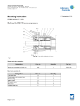
Fig. 2: The WHC system (without hoses), part no. 3446.1004.

Installation and operating manual - Sabroe WHC circulation system
8/17 011162 en 2021.05
Design and function
The complete WHC system (without hoses), part. no. 3446.1004, consists of:
Position Quantity Part no. Description
1 1 2214.1018 Bracket 1 for WHC system
2 2 2214.1013 Bracket 2 for WHC system
3 2 1349.265 Straight screw joint
4 1 1553.1045 Flow switch
52 1346.215 Nipple pipe 1/2” 100 mm
6 6 1367.078 Pipe clamp Ø21.3 single
7 3 1352.1003 Female adapter 1/2” – 2”
8 2 1341.1000 T-piece 2”
9 1 1375.1008 Air screw 1/2”
10 1 1345.1014 Nipple pipe 2” 120 mm
11 4 1344.1030 Union 1/2
12 3 1341.1001 T-piece 1/2”
13 1 1555.1009 Heating element 1000 W
14 4 1345.1013 Nipple pipe 1/2” 80 mm
15 2 1363.045 Ball valve
16 1 1372.282 Valve solenoid NC
17 1 1372.537 Coil 10 W
18 1 1375.008 Frese DN15 Needle valve
19 3 1345.1016 Nipple pipe 1/2” 30 mm
20 2 1375.147 Strainer 1/2”
21 1 1364.1010 Check valve
22 1 1341.1002 Elbow 90 deg. 1/2” – 1/2”
23 2 1352.1005 Female adapter 1/2” – 1”
24 1 1524.1003 Pump union set 1.1/2” – 1”
25 1 3448.1000 Control box, including ir33 controller (25–a)
25–a 1 3448.2003 Carel ir33 preprogrammed controller
26 1 1524.1103 Water pump
27 12 1424.157-E Screw M6x45
28 1 1342.1000 Hexagon nipple R3/4” – R1/2”
29 1 1364.1030 Safety valve 10 bar
30-a 4 1424.191-E Screw M10x25
30-b 4 1432.059 Nut M10
30-c 4 1436.035 Washer 21/10.5x2.0
31 4 1413.334 Screw M6x1 L= 12.9 DIN 912

Installation and operating manual - Sabroe WHC circulation system
011162 en 2021.05 9/17
Mounting and connections
4. Mounting and connections
If the circulation system is sold with a heat pump or a chiller, the system will already be
mounted and connected on delivery.
If the system is sold with a compressor unit, it will not be fastened as the system should not be
mounted directly on the compressor or the compressor base frame because of vibrations.
Mounting
The circulation system is mounted on a plate bracket which can be fastened to the floor, wall or
other suitable place directly or by means of two angular brackets. See Fig. 3.
Fig. 3
Warning!
The circulation system must not be exposed to heavy vibrations. It is not recommended to
mount the circulation system directly on the compressor or compressor base frame.
Dismounting and lifting
The WHC system can be dismounted by unscrewing the four screws, (Fig. 2, pos. 30). The
system weighs approximately 17 kg and can be lifted in the oblong hole above the controller.
Cooling water supply
On the supply side, the circulation system can receive water from local waterworks, a cooling
tower or a brine circuit. The pump (Fig. 2, pos. 26) circulates the cooling media during standstill
and operation, but does not supply the system with cooling water (or brine) during operation.
There must be either a minimum 0.2 bar differential pressure between inlet and outlet (Pinlet >
Poutlet) or a second supply pump must be installed to feed the system.
A supplementary supply pump, see Fig. 4, can be controlled by the WHC control box. The sup-
ply pump will be energized together with the solenoid valve, as cooling water is only needed in
cooling mode. The WHC control box is equipped with additional terminals and cable connec-
tions for the supplementary supply pump (max. 100W).
The WHC pump, Alpha 2 part no. 1524.1103, can also be used as supply pump.

Installation and operating manual - Sabroe WHC circulation system
10/17 011162 en 2021.05
Mounting and connections
Fig. 4
On the circulation side, the system must be connected to the compressor cooling hoses by the
two provided cooling hoses. The two provided hoses are of a length allowing them to be cut to
the length required.
Quantity Part no. Description
1 3185.1000 Set of connecting hoses
(WHC – Compressor)
1See the compressor spare parts
manual Set of hoses for compressor block
Fig. 5
Pressure testing
The system is not pressure tested on delivery.
Max. test pressure: 10 bar.
Supplementary pump
Inlet
Outlet
To compressor
From compressor

Installation and operating manual - Sabroe WHC circulation system
011162 en 2021.05 11/17
Mounting and connections
During pressure testing, the regulating valve (Fig. 2, pos. 18) and the solenoid valve (Fig. 2,
pos. 16) must be open.
Draining
The system must be turned off before draining as the heating element and pump may be dam-
aged if there is air in the system.
Draining can be done through the safety valve (Fig. 2, pos. 29) by turning the cap or by open-
ing one of the strainers Fig. 2, pos. 20).
Purging
The system must be purged from air. This can be done by carefully loosening the air screw (
Fig. 2, pos. 9) or by unscrewing a fitting (just a little) on one of the compressor cooling hoses. If
the water circuit in general is not free of air, it is recommended to replace the air screw (Fig. 2,
pos. 9) with an automatic air vent valve.
Warning!
Scalding risk. The water in the system is hot both during operation and standstill.
Electrical installation
If the WHC system is bought as part of a Sabroe heat pump or chiller, it is connected to the
compressor electrical panel and it requires no additional control. The circulation pump, sole-
noid valve and heating element are supplied and controlled by the regulator in the terminal
box.
If the system is bought on its own, the following requirements are strongly recommended:
• A circuit-breaker and a back-up fuse for the system should be installed so that it can be
switched off during service, maintenance and shutdown of equipment.
• A compressor running signal*. See Appendix B.
• Stop input (alarm) in the compressor controller**. See Appendices A & B.
* It is possible to use the WHC system even if a compressor running signal is not available.
However, this means that a jumper must be installed in the WHC control box (Appendix B).
Furthermore, the set point for the heating element (St1) must be set 5°K lower than the sole-
noid valve set point (St2). If not, the heating element will be on at the same time as the sole-
noid valve is energized (cooling and heating at the same time).
** If the alarm signal for the WHC control box is not connected to the compressor controller,
the compressor will not be protected against failure in the cooling/heating circuit.
Supply voltage: 1 x 230 V +/-10%, 50/60 Hz
Output: 1100 W
Max. fuse: 6 amp
Dry run protection
The system is protected against dry running by a flow switch (Fig. 2, pos. 4).
If the water supply fails, the run signal to the Unisab compressor controller is disconnected,
and so is the power to the heating element (Fig. 2, pos. 13).
For further description of the flow switch, see Appendix F.

Installation and operating manual - Sabroe WHC circulation system
12/17 011162 en 2021.05
Start-up and commissioning
5. Start-up and commissioning
The circulation system must be charged with water and air purged before voltage is applied to
the system.
Warning!
Scalding risk. The water in the system is hot both during operation and standstill.
Setting the water temperature
Standstill (heating mode)
While the compressor is stopped, the WHC system is in heating mode, which means that the
heating element is regulating the temperature. The temperature of the circulated media must
be minimum 10°K above the corresponding R717 equalizing pressure (saturated temperature)
at standstill to avoid condensation inside the compressor.
For the WHC system, the equalizing pressure is defined as the same as the compressor pres-
sure 15 minutes after stopping the compressor.
For Sabroe HeatPAC, ChillPAC and DualPAC, the approximate equalizing pressure can be
calculated by this formula: Pequal = 0.18 x Pdiscaharge + Psuction -1, [bara].
The default set point (St1) for the heating element is 60°C.
To change the heating element set point (St1):
• Press Set: the display shows St1 and the current value of St1
• Press ▼ or ▲ to reach the desired value
• Press Set to confirm the new value of St1
• The display returns to the standard view.
Running (cooling mode)
While the compressor is running the WHC-system is in cooling mode, this means that the sole-
noid valve is regulating the temperature. The controller must be set so the cooling water can
hold the compressor oil and discharge temperature below the maximum operating limits.
The default set point (St2) for the solenoid value is 45° C, which will be okay for most
conditions.
To change the heating element set point (St2):
• Press Set twice slowly: the display shows St2 and the current value of St2
• Press ▼ or ▲ to reach the required value
• Press Set to confirm the new value of St2
• The display returns to the standard view.
Note: If the WHC system has been bought separately and a compressor running signal is not
available, the set point for the heating element (St1) must be set 5° K lower than the solenoid
valve set point (St2). If not, the heating element will be on at the same time as the solenoid
valve is energized (cooling and heating at the same time).

Installation and operating manual - Sabroe WHC circulation system
011162 en 2021.05 13/17
Start-up and commissioning
Maximum and minimum media temperature
The controller is set up to stop the compressor if the cooling media is either too cold or too
warm.
• Minimum (alarm) temperature: 35°C.
• Maximum (alarm) temperature: 85°C.
For further description of the controller, see Appendices A & B.
Flow setting of regulating valve
The setting of the regulating valve (Fig. 2, pos. 18) depends on the size of the compressor as
well as operating conditions, cooling water temperature and differential pressure between inlet
and outlet.
If the cooling water temperature is fluctuating heavily, the fluctuations can be damped by throt-
tling the valve.
For setting of regulating valve, see also Appendix D.
Setting of pump
The circulation pump is set at maximum flow from factory: Constant flow speed III.
For setting of pump, see also Appendix C.

Installation and operating manual - Sabroe WHC circulation system
14/17 011162 en 2021.05
Alarms
6. Alarms
Low flow
• The electric plug LED at the flow switch (Fig. 2 , pos. 4) will be on.
• The heating element will be disconnected.
• The compressor will stop (if the WHC control box is connected to the compressor
controller).
Note: The WHC control panel will NOT indicate alarm for low flow.
Low temperature
The WHC control panel will show the alarm E05 (default 35°C).
High temperature
The WHC control panel will show the alarm E05 (default 85°C).

Installation and operating manual - Sabroe WHC circulation system
011162 en 2021.05 15/17
Service and maintenance
7. Service and maintenance
It is recommended to check the cooling water temperature regularly and ensure that the sys-
tem is working optimally. See the subsection "Setting of water temperature" in section 5.
The strainer (Fig. 2, pos. 20) should be checked and cleaned of dirt on a regular basis. If addi-
tional space is needed during service of the compressor unit, the circulation system can be
detached.
Warning!
Power must be switched off before the system is detached.
Warning!
Scalding risk. The water in the system is hot both during operation and standstill.

Installation and operating manual - Sabroe WHC circulation system
16/17 011162 en 2021.05
Technical data and dimensions
8. Technical data and dimensions
Supply voltage: 1 x 230 V +/-10%, 50/60 Hz
Output: 1200 W
Ambient temperature: 0°C to 40°C
Liquid temperature: 2°C to 93°C
System pressure: Max. 10 bar
Inlet pressure: Min. 0.3 bar
Differential pressure (in/out): Min. 0.2 bar
Weight: Approx. 17 kg
Fig. 6
(280)
371
(783)
Flow
FlowFlow
Flow

Installation and operating manual - Sabroe WHC circulation system
011162 en 2021.05 17/17
Appendices
9. Appendices
A: Quick guide – WHC control box
B: Manual – WHC control box
C: Grundfos instructions, Alpha 2
D: Frese, SIGMA regulating valve
E: Danfoss, EV250B solenoid valve
F: SIKA, VHS15M flow switch
G: Immersion heater, 1000 W.

Johnson Controls Denmark ApS
Sabroe Factory
Christian X's Vej 201 ∙ 8270 Højbjerg
Denmark
Phone +45 87 36 70 00
www.sabroe.com
Version 4

Quick guide – WHC control box (Carel IR33)
00010049 en 2019.05 1/7
Quick guide – WHC control box (Carel IR33)
Understanding the display
Display icons:
Quick guide WHC control box (Carel IR33)
Understanding the display
Display icons:
Temperature alarms:
E05= Low temperature >35°C
E04= High temperature<85°C
Other Alarms: See Alarm list (last page)
Temperature alarms
• E05= Low temperature >35°C
• E04= High temperature<85°C
For other alarms, see the ‘Alarm list’ on the last page.
Appendix A
Quick guide – WHC control box (Carel IR33)

Quick guide – WHC control box (Carel IR33)
2/7 00010049 en 2019.05
Quick guide – WHC control box (Carel IR33)
Displaying inputs
Press ▼: The current input will be displayed, alternating with the value.
b1: Probe 1 (measured temperature)
b2: Probe 2 (measured temperature)
di1: Digital input 1 (OPn/CLO)
di2: Digital input 2 (OPn/CLO)
St1: Setpunkt 1
St2: Setpunkt 2
Displaying the inputs
Press ▼: The current input will be displayed, alternating with the value.
b1: Probe 1 (measured temperature)
b2: Probe 2 (measured temperature)
di1: Digital input 1 (OPn/CLO)
di2: Digital input 2 (OPn/CLO)
St1: Setpunkt 1
St2: Setpunkt 2
• Press ▼ or ▲ to select the input to be displayed
• Press Set for 3 seconds to confirm. The selected input will now be showed in the display. b1
should always be the standard input displayed.
!!! When the controller scanning the inputs, a digital input has not been configured, the display
will show “nO” (indicating that the digital input has does not exist or has not been configured).
When the controller shows “Opn” or “CLO”, it indicates, respectively, that the input is open or
closed. For the probes, the value displayed will be the value currently measured by the probe
or, if the probe is not fitted or not configured, the display will show “nO”.
• Press ▼or ▲to select the input to be displayed
• Press Set for 3 seconds to confirm. The selected input will now be showed in the display.
b1 should always be the standard input displayed.
When the controller scans the inputs and a digital input has not been configured, the display will
show “nO” (indicating that the digital input does not exist or has not been configured).
When the controller shows “Opn” or “CLO”, it indicates that the input is open or closed respec-
tively. For the probes, the value displayed will be the value currently measured by the probe, or, if
the probe is not fitted or not configured, the display will show “nO”.
/