Page is loading ...

NS-HPAC/DualPAC
with reciprocating compressors
Operating manual EN


Operating manual – DualPAC with reciprocating compressors
0012201 en 2021.04 3/64
Manual for DualPAC heat pump
Unit type
Compressor types
Designations
Compressor nos.
Refrigerant R717
Oil type PAO 100 Other:
Level control Mechanical float valve Electronic valve
Approval PED (2014/68/EU) Other:
Supply voltage Motor: 3 x ______ V / ____ Hz
Control: 1 x ______ V / ____ Hz
Motor IP23 IP55 Δ/D VSD
Power: ______ kW Size IEC: ______
Ex-execution
Both compressor and unit are safeguarded

Operating manual – DualPAC with reciprocating compressors
4/63 0012201 en 2021.04
Safety valve:
Data for calculation of
downstream line accord-
ing to EN 13136
Vessel data
Type External surface
[m2]
Design pressure
[bar]
Condenser HP
Condenser LP
Evaporator
Oil separator HP
Oil separator LP
Oil cooler
Intermediate vessel
Economiser
Desuperheater
Subcooler
Other
Pressure loss, if any, from safety valve to customer connection
(based on design pressure) [bar] _____________
Safety valve type:
Back-pressure dependent
Back-pressure independent

Operating manual – DualPAC with reciprocating compressors
0012201 en 2021.04 5/63
Contents
1. Introduction ..................................................................................... 8
1.1 Definition of safety precautions used in this manual ............. 9
1.2 Requirements for competent persons .................................... 9
2. Safety............................................................................................... 10
2.1 Area of application................................................................. 10
2.1.1 Application of the DualPAC pump .................................. 10
2.1.2 Application of combustion engines ................................ 10
2.2 Identification ......................................................................... 11
2.2.1 Identification of equipment............................................ 11
2.2.2 Compressor name plates ............................................... 12
2.2.3 Vessel name plate .......................................................... 14
2.2.4 Unit/pipe system name plate......................................... 15
2.2.5 Signs .............................................................................. 17
2.3 Safety precautions ................................................................ 18
2.3.1 General precautions ....................................................... 18
2.3.2 During operation ............................................................ 18
2.3.3 Water system.................................................................. 19
2.3.4 Brine................................................................................ 19
2.3.5 Safety during maintenance and service ........................ 19
2.3.6 Power supply .................................................................. 19
2.3.7 Lubricating oils ............................................................... 20
2.3.8 Refrigerants .................................................................... 20
2.3.9 Purging of DualPAC......................................................... 20
2.3.10 First aid for accidents with ammonia ............................. 22
2.3.11 Protecting the operator as well as the
environment ................................................................... 23
2.3.12 Emergency stop.............................................................. 24
3. Design and function ...................................................................... 25
3.1 Unit design............................................................................. 25
3.1.1 General DualPAC information ........................................ 25
3.1.2 DualPAC description ....................................................... 26
3.2 Main components .................................................................. 27
3.2.1 Compressors................................................................... 27
3.2.2 Control system ............................................................... 27
3.2.3 Evaporator ...................................................................... 27
3.2.4 GHUR intermediate cooler ............................................. 27
3.2.5 Condenser ...................................................................... 27
3.2.6 Receiver .......................................................................... 28
3.2.7 Air purge valve ............................................................... 28
3.2.8 Pressure regulation system (electrical)......................... 29

Operating manual – DualPAC with reciprocating compressors
6/63 0012201 en 2021.04
3.2.9 Automatic oil recovery system from evaporator........... 30
3.2.10 Automatic oil return from oil separator ......................... 31
3.2.11 By-pass function during start-up................................... 31
3.2.12 WHC circulation system ................................................. 31
3.2.13 Discharge check valve.................................................... 33
3.2.14 Function of CVP valves ................................................... 34
4. Installation information .............................................................. 35
4.1 Installation............................................................................. 35
4.1.1 General information ....................................................... 35
4.1.2 First start-up procedure ................................................. 35
4.2 Sound and vibrations ............................................................ 36
4.2.1 General information ....................................................... 36
4.2.2 Sound and noise data..................................................... 36
4.2.3 Foundation...................................................................... 36
4.2.4 Vibration dampers.......................................................... 37
4.2.5 Variable speed drive ....................................................... 37
4.3 Secondary system ................................................................. 37
4.3.1 General information ....................................................... 37
4.3.2 Cleaning in place ............................................................ 38
4.3.3 Temperature and flow control ........................................ 38
4.3.4 Water and brine treatment............................................. 38
4.3.5 R717 detector................................................................. 38
5. Operating instructions ................................................................. 39
5.1 Personnel qualification requirements ................................... 39
5.2 Pre-start check ...................................................................... 39
5.3 Starting .................................................................................. 39
5.3.1 Starting procedures ....................................................... 39
5.3.2 Normal start-up procedure ............................................ 40
5.3.3 Valve positions during operation ................................... 41
5.3.4 Restarting DualPAC after power interruption................ 42
5.3.5 Restarting DualPAC after alarm stop
(shutdown) ..................................................................... 42
5.3.6 Stopping for a brief period ............................................. 43
5.4 During operation ................................................................... 43
5.4.1 Checks to be performed during operation..................... 43
5.4.2 Monitoring and logging of operation.............................. 43
5.5 Stopping procedures ............................................................. 43
5.5.1 Stopping for a brief period ............................................. 43
5.5.2 Shutting down for a long standstill period..................... 44

Operating manual – DualPAC with reciprocating compressors
0012201 en 2021.04 7/63
5.6 Shutdown and alarms ........................................................... 45
5.6.1 Operating state............................................................... 45
5.6.2 Troubleshooting.............................................................. 45
5.6.3 Testing of DualPAC units ................................................ 46
6. Maintenance instructions............................................................ 47
6.1 Maintenance of DualPAC units .............................................. 47
6.2 Selecting lubricating oil for DualPAC units ........................... 48
6.3 R717 charge........................................................................... 48
7. Final disposal ................................................................................. 49
7.1 Safety precautions ................................................................ 49
7.2 Waste disposal....................................................................... 49
8. Appendices ..................................................................................... 50
8.1 Monitoring of operation ......................................................... 50
8.2 Control description - DualPAC............................................... 51
8.3 Spare parts list for CVUA 1201 oil recovery pot ................... 52
8.4 Declaration of conformity...................................................... 53
8.5 Set-up guide — AKS 4100 280 mm
for ammonia heat pump application ..................................... 54
Index................................................................................................ 62

Operating manual – DualPAC with reciprocating compressors
8/63 0012201 en 2021.04
Introduction
1. Introduction
This manual is primarily intended for operators and engineers.
It describes the combined service of a HeatPAC heat pump and a ChillPAC chiller when these are
operating as a DualPAC.
To prevent accidents, assembly and disassembly of components should be carried out by compe-
tent persons only.
• It is important that the operating personnel familiarise themselves with the contents of
this manual in order to ensure a proper and efficient operation. Johnson Controls Den-
mark is not liable for damage occurring during the warranty period where this is attribut-
able to incorrect operation.
• All compressor intervention within the warranty period must be performed by competent
personnel only. If not, the warranty no longer applies.
For further information, see www.sabroe.com
This manual is produced by:
Johnson Controls Denmark ApS
Christian X's Vej 201
8270 Højbjerg, Denmark
Phone +45 87 36 70 00
CVR No 19 05 61 71
www.sabroe.com
Copyright © Johnson Controls Denmark
This manual must not be copied without the written permission of Johnson Controls Denmark and
the contents must not be imparted to a third party nor be used for any unauthorised purposes.
Contravention will be prosecuted.
The original version of this manual is the English language version. If there are any discrepancies
or conflicts between the English and any other version that has been translated into another lan-
guage, the English version will prevail.

Operating manual – DualPAC with reciprocating compressors
0012201 en 2021.04 9/63
Introduction
1.1 Definition of safety precautions used in this manual
Danger!
Indicates an imminently hazardous situation which, if not avoided, will result in death or serious
injury.
Warning!
Indicates a potentially hazardous situation or practice which, if not avoided, will result in death or
serious injury.
Caution!
Indicates a potentially hazardous situation or practice which, if not avoided, will result in damage
to equipment and/or minor injury.
Note: Indicates an operating procedure, practice, etc., or portion thereof, which is essential to
highlight.
1.2 Requirements for competent persons
• Personnel working on the unit must be competent in accordance with national safety rules
and regulations relating to flammable refrigerants or according to EN 13313.
• Maintenance work must be performed according to EN 378 or ISO 5149 supported by evi-
dence of appropriate training.
• Assign only competent personnel instructed in safety and all machine functions to operate
or service the compressor/unit according to EN 13313.
• Operators and maintenance personnel must carefully read, understand and fully comply
with all alarms and instructions.

Operating manual – DualPAC with reciprocating compressors
10/63 0012201 en 2021.04
Safety
2. Safety
2.1 Area of application
2.1.1 Application of the DualPAC pump
To prevent unintentional application, which could injure personnel or damage equipment, the fol-
lowing must be observed:
• The unit must only be used as a DualPAC intended for heating and cooling of water or con-
densing refrigerant gas in the evaporator.
• The unit must not be installed in areas where the relative humidity (RH) may exceed 85%
(95% if the motor is made for 100% RH).
• The primary side must only be charged with refrigerant R717.
• Johnson Controls Denmark further accept no liability of any kind for damage to compres-
sor unit and plant parts caused by torsional oscillation or the like which is attributable to
built-in VSD solutions initiated by the customer after delivery.
• The secondary side on the evaporator and condenser is only intended for water or brine as
process medium. The secondary medium is stated in the P&I diagram. Deviations are only
permitted with a written permission from Johnson Controls Denmark.
• Installation of the heat pump/unit in potentially explosive atmospheres must only take
place if the DualPAC is fitted with approved explosion-proof equipment.
• The compressor must only be used as a compressor within the operating limits specified
in the compressor manual or in a written agreement with Johnson Controls Denmark.
• The compressor must only be used with the number of revolutions per minute, as shown
on the compressor name plate.
The compressor must NOT be used:
• To evacuate the heat pump of air and moisture
• To put the DualPAC under air pressure in view of a pressure testing
• As an air compressor.
2.1.2 Application of combustion engines
According to EN 378/ISO 5149, no other machinery should be installed in a refrigeration machine
room. Some refrigerant types may, to a certain extent, be absorbed by the fuel in a combustion
engine, and when the contaminated fuel reaches the fuel pumps, the refrigerant will “flash out”
(separate) and react on the increased temperature and pressure by creating acids, which will de-
stroy the pumps. However, check with the local authorities as exemptions to this rule may be
granted.
Warning!
Johnson Controls Denmark is not liable for injuries to personnel or damage to equipment resulting
from using the equipment for other purposes than the ones stated above.

Operating manual – DualPAC with reciprocating compressors
0012201 en 2021.04 11/63
Safety
2.2 Identification
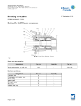
2.2.1 Identification of equipment
All equipment from Johnson Controls Denmark can be identified by one or several name plates
positioned as illustrated in the following drawings:
Fig. 1: Positioning of name plates on DualPAC
Pos. no. Designation
1Compressor name plate
2Vessel name plate
3Unit / Pipe system name plate

Operating manual – DualPAC with reciprocating compressors
12/63 0012201 en 2021.04
Safety
2.2.2 Compressor name plates
Compressor
Refrigerant
Swept volume
Pressure system
Allowable pressure
Test pressure
LP side HP side
No
Type
Year
Speed
bar g
bar g
m3/h
Max.
rpm
2516-345
Fig. 2: Name plate for standard compressor
Compressor
Refrigerant
Swept volume
Pressure system
Allowable pressure
Test pressure
LP side HP side
No
Type
Year
Speed
bar g
bar g
m3/h
Max.
rpm
Fig. 3: Name plate for ATEX compressor
Fig. 4: Name plate for compressor with EurAsian Con-
formity mark (EAC)
Johnson Controls Denmark ApS
Christian X's Vej 201
8270 Højbjerg, Denmark
www.sabroe.com
Test pressure
Allowable pressure
Pressure system
LP side
HP side
Year
No
Type
Refrigerant
Compressor
Swept Volume
Speed
psig
psig
rpm
cfm
2516-347
Max.
Fig. 5: Name plate for compressor to the USA

Operating manual – DualPAC with reciprocating compressors
0012201 en 2021.04 13/63
Safety
The compressor name plate is positioned on the compressor and contains this information:
Compressor no. Identification no. (serial no).
Year Year of manufacturing.
Type Manufacturer's type designation.
Refrigerant
Allowable refrigerant or refrigerants for the compressor.
(The actual refrigerant for the unit is stated on the unit name
plate).
Speed
Specific rotational speed. Specific rotational speed is used for cal-
culating swept volume. For the actual allowed operating speed,
please refer to the operating limits and Matchmaster's calculation
on the actual operating condition.
Swept volume Swept volume of the compressor at nominal speed.
Pressure system
The low-pressure side of the compressor is referred to as the LP
side.
The high-pressure side of the compressor is referred to as the HP
side.
Allowable pressure, max.
The max. pressure (pressure relative to atmospheric pressure)
that the compressor has been designed for in terms of pressure
strength design.
The maximum practical operation pressure is lower than the maxi-
mum allowable pressure, depending on the operating conditions
and safety equipment settings.
Test pressure The test pressure the compressor has been strength tested with.
CE and Ex The CE and Ex marks indicate that the compressor has been de-
signed in accordance with the EC ATEX directive.
EAC
The EurAsian Conformity mark (EAC) indicates that the compres-
sor is in compliance with all relevant technical regulations of the
Eurasian Customs Union.

Operating manual – DualPAC with reciprocating compressors
14/63 0012201 en 2021.04
Safety
2.2.3 Vessel name plate
Fig. 6: Name plate for vessel
Пpoeкт пo cтaндapтy
Design code
Утвepждeн пoд N
°
Approval No
Oбъeм
/Volume
Cpeдa
/Fluid
Тип
/Type
PS
TS
V
M
асса
пустого
cocy
д
a
Empty weight
/
Кат
.
/Cat.
Nº cocy
д
a
Vessel No
год
2516-331
кг
Cтopoнa oбeчaйки
Shell
side
Tube side
Cтopoнa тpyбок
п
l
MПа
MPa
°C
P
a
б
o
ч
ee
двп
e
ни
e
Макс
./
Мин
.
Allowable pressure
Max./Min.
P
aбoчaя тeмпepaтypa
Макс
./
Мин
.
Allowable temperature
Max./Min.
Kg
Year
Johnson Controls Denmark ApS
Christian X's Vej 201
8270 Højbjerg, Denmark
www.sabroe.com
Fig. 7: Name plate for vessel with EurAsian Conformity
mark (EAC)
The pressure vessel name plate is positioned on the shell of the vessel and contains this
information:
Vessel no. Identification no. (serial no.)
Empty weight The empty weight of the vessel in kg.
Year Year of manufacturing.
Type Manufacturer's type designation.
Design code Design code used for the pressure vessel.
Approval no./CAT
The approval no. of the vessel issued by the relevant 3rd party/
notified body.
For EC PED approval: CAT (Category 1, 2, 3 or 4) according to the
PED directive.
Side For heat exchangers only. Refers to the columns ‘Shell side’ and
‘Tube side’.
Fluid
Designation of the primary refrigerant(s) and the secondary re-
frigerant(s).
For EC PED approval: Designation of the refrigerant(s) and/or the
highest fluid group (Group 1 or 2) according to the PED directive.
Allowable pressure, PS The min. and max. pressures (pressure relative to atmospheric
pressure) that the vessel or vessel part has been designed for.
Allowable temperature,
TS
The min. and max. temperatures that the vessel or vessel part has
been designed for.
Volume The volume of the vessel or vessel part.
CE xxxx
The CE mark appears on the name plate for EC PED approval.
The four digits make up the registration no. of the notified body/
3rd party in charge.
EAC
The EurAsian Conformity mark (EAC) indicates that the vessel is
in compliance with all relevant technical regulations of the Eura-
sian Customs Union.
Note: Depending on the supplier of the pressure vessel/heat exchanger, the layout and content
of the vessel name plate may differ from the Sabroe name plate above.
Johnson Controls D e n m ar k ApS
Christian X 's V e j 201
8 270 Højbj e rg, D e n m ark
www.sabro e .com

Operating manual – DualPAC with reciprocating compressors
0012201 en 2021.04 15/63
Safety
2.2.4 Unit/pipe system name plate
Scope
Design code
Approval No
Refrigerant
Supply voltage
Test pressure
Allowable pressure
Category
Pressure system
Refrigerant charge
Max.
Allowable temp.
Min./Max.
Refrigeration unit
No
Type
Year
Fluid
Group
Control
V/Hz
kg
bar
g
bar
g
°C
LP side HP side
2516-342
Johnson Controls Denmark ApS
Christian X's Vej 201
8270 Højbjerg, Denmark
www.sabroe.com
Fig. 8: Name plate for standard unit
Scope
Design code
Approval No
Refrigerant
Supply voltage
Test pressure
Allowable pressure
Category
Pressure system
Refrigerant charge
Max.
Allowable temp.
Min./Max.
Refrigeration unit
No
Type
Year
Fluid
Group
Control
V/Hz
kg
bar
g
bar
g
°C
LP side HP side
Johnson Controls Denmark ApS
Christian X's Vej 201
8270 Højbjerg, Denmark
www.sabroe.com
2516-343
Main
Fig. 9: Name plate for ATEX unit
Установка холодильная
№
Назначение
Код стандарта
№
сертификата
Хладагент
Жидкость
Группа
Напряжение питания Сеть
Управ
ление В/Гц
Заправка хладагентом
Кг
Давление
бар
бар
Допустимое давление
Давление ислытания
Сторона НД
макс
Сторона ВД
Категория
°
С
Допустимая темп
мин/макс
Год
Тип
2516-344
Johnson Controls Denmark ApS
Christian X's Vej 201
8270 Højbjerg, Denmark
www.sabroe.com
Fig. 10: Name plate for unit with EurAsian Conformity
mark (EAC)

Operating manual – DualPAC with reciprocating compressors
16/63 0012201 en 2021.04
Safety
The unit name plate is positioned on the frame and contains this information:
Refrigeration unit No. Identification no. (serial no.)
Year Year of manufacturing.
Type Manufacturer's type designation.
Scope
For EC PED/EAC approval: ‘Unit & Piping’ means that the CE/EAC
mark applies to the complete unit including the piping system.
’Piping’ means that the CE/EAC mark applies to the piping system
only, and it is the sole responsibility of the owner to ensure and
declare that the complete unit is in conformity with the provisions
of all relevant rules.
Design code Design code used for the unit and piping system.
Approval no. If the unit/manufacture has been approved by a 3rd party/notified
body.
Refrigerant - Fluid Refrigerant of the unit.
Refrigerant designation according to ISO 817.
Refrigerant - Group For EC PED approval:
Fluid group 1 or 2 according to the PED directive.
Supply voltage - Control Supply voltage and frequency of the control system.
Refrigerant charge
Weight of the refrigerant charge on the unit.
This is only stated if the unit includes an evaporator and/or a
condenser.
Pressure system
The low-pressure side of the unit piping system is referred to as
the LP side.
The high-pressure side of the unit piping system is referred to as
the HP side.
Category
For EC PED approval:
The maximum category of the piping system (CAT 1, 2 or 3) or of
the assembly unit and piping (CAT 3 or 4).
Allowable pressure, max.
The max. pressure (pressure relative to atmospheric pressure)
that the unit/piping system has been designed for in terms of
pressure strength design.
The maximum practical operation pressure is lower than the maxi-
mum allowable pressure depending on the operating conditions
and safety equipment settings.
Test pressure The test pressure that the unit/piping system has been strength
tested with.
Allowable temperature,
min./max.
The minimum and maximum temperatures that the unit/piping
system has been designed for at the indicated maximum allowable
pressures.
CE xxxx
The CE mark appears on the name plate for EC PED approval only.
The four digits make up the registration no. of the notified body/
3rd party in charge.
Ex If the unit is designed in accordance with the EC ATEX directive,
there is an Ex mark on the name plate.
EAC
The EurAsian Conformity mark (EAC) indicates that the unit is in
compliance with all relevant technical regulations of the Eurasian
Customs Union.
Note: Main supply voltage can be found on the motor and/or electrical panel name plate.

Operating manual – DualPAC with reciprocating compressors
0012201 en 2021.04 17/63
Safety
2.2.5 Signs
All signs which may be found on your equipment are shown below. The number of signs, however,
may vary from one product to another.
Risk of electric shock High voltage/
High pressure
High surface
temperature
(about 70°C)
The compressor may be
top-heavy
Internal overpressure Hazardous substance Cold surfaces Dangerous noise level,
use hearing protectors
Do not step on surface No open flame Flammable gas The unit IS filled with re-
frigerant R290
Internal protection Pacemaker users keep out
Compressor blocks and units are usu-
ally delivered without refrigerant and
oil. To protect the compressors against
internal corrosion, they are delivered
evacuated of all atmospheric air and
charged with dry Nitrogen (N2) to an
overpressure of 0.5 bar [7.3 PSI].
In such cases, a yellow sign is affixed
to a visible spot on the compressor.
The magnetic field on the rotor may
affect pacemakers. The motor rotor
contains a powerful magnetic field.
This field may affect digital devices
such as watches and mobile phones.
Assembly or maintenance of the rotor
must not be carried out by people with
pacemakers or any other implanted
medical electronic device.
The VSD contains capacitors capable
of storing electrical energy, meaning
that there is a risk of electric shock
within 15 minutes after the drive has
been turned off.

Operating manual – DualPAC with reciprocating compressors
18/63 0012201 en 2021.04
Safety
2.3 Safety precautions
2.3.1 General precautions
These precautions should be used as a supplement to the safety precautions and warnings in-
cluded in:
• All other manuals pertaining to the compressor/unit
• Local, plant and shop safety rules and codes
• National safety rules and regulations.
Read and understand all safety instructions before setting up, operating or servicing/performing
maintenance on the compressor/unit. Assign only competent personnel instructed in safety and
all machine functions to operate or service the compressor/unit.
Operators and maintenance personnel must carefully read, understand and fully comply with all
alarm and instruction plates mounted on the compressor/unit.
• Observe the safety warnings.
• Use ear protection when operating the compressor/unit.
• Use safety equipment. Wear appropriate gloves as well as eye and face protection when
working with parts containing refrigerant and/or lubricating oil.
• Use proper electrical safety protection.
Note: These instructions only provide general information. The owner of the refrigeration plant is
responsible for ensuring that all codes, regulations and industry standards are complied with.
2.3.2 During operation
Warning!
All safety features, disengagement and interlocks must be in place and function correctly before
the equipment is put into operation. Never by-pass or wire around any safety device.
Ventilation
Before operating the unit always check, where relevant, the function of the ventilation system
and refrigerant detectors used in the area where the compressor/unit is located (machine room).
Rotating parts
Warning!
Safety guards, shields, barriers, covers and protective devices must not be removed while the
compressor/unit is operating.
Vibration and noise
During operation, pay attention to the compressor unit process. Excessive vibrations, unusual
sounds, etc. may indicate problems requiring your immediate attention.
Pressure
Danger!
A compressor/unit comprises a pressurised system. Never loosen threaded joints while the sys-
tem is under pressure, and never open pressurised system parts.

Operating manual – DualPAC with reciprocating compressors
0012201 en 2021.04 19/63
Safety
Note: Whenever a relief valve/safety valve has been activated, we recommend recalibrating it.
This must be carried out by competent personnel only. See also EN 378 and existing national
legislation.
2.3.3 Water system
Warning!
The recirculation water system may contain chemicals or biological contaminants, including le-
gionella, which can be harmful if inhaled or ingested. Water systems should only be operated with
an effective biological treatment programme.
2.3.4 Brine
In recent years alcohol, glycol and halogenated compounds have been used in the production of
brine.
In general, all brines must be considered harmful to nature and they must be used with caution.
Be very careful when charging or purging a refrigeration plant.
Never empty brines down a sewer or into the environment.
The brine must be collected in suitable containers clearly marked with the contents and sent to an
approved incineration plant.
2.3.5 Safety during maintenance and service
• Personnel must be competent according to national safety rules and regulations and per-
form the maintenance work according to EN 378 and EN 13313/ISO 22712.
• Read chapter 2. Safety in this manual before opening the compressor and other parts of
the refrigeration plant. If the switch is not locked, all start buttons must be tagged with
“DO NOT START” tags and an explanation: “Work on unit in progress”.
• Make sure that the motor cannot start up inadvertently. Switch off all electric components
on the compressor/unit before starting the dismantling/servicing process. It is recom-
mended to remove all main fuses.
• Make sure that there is no over-pressure and no refrigerant in the part to be dismantled.
Close all necessary stop valves.
• Use the prescribed tools, and check that they are properly maintained and in good work-
ing condition. In explosion-proof areas, use tools suited for this specific purpose.
• Use only Johnson Controls Denmark original spare parts; other parts may impair the
safety of the compressor/unit.
• Use gloves and protective goggles, and make sure to have a gas mask close at hand.
2.3.6 Power supply
Danger!
•The voltage used in the drive can cause severe electric shock and/or burns and may be le-
thal. Extreme care must be taken at all times when working with or close to the drive. Spe-
cific warnings are given wherever relevant in this manual.
•The drive line is connected to voltage. Be aware of live circuits.
•Pay close attention to the electrical installation and system maintenance to avoid hazards
both during normal operation or in the event of equipment malfunctioning.

Operating manual – DualPAC with reciprocating compressors
20/63 0012201 en 2021.04
Safety
•When the cause of the shutdown has been removed, the motor may restart. This can be
dangerous for machines and installations, and it is therefore important that the user takes
adequate precautions against restarting if the motor makes an unscheduled stop.
•System maintenance must always be carried out by personnel who have the necessary
training and experience.
2.3.7 Lubricating oils
Compressor oils include the following oil types:
Code design Oil types
MMineral oil, naphtenic base
ASynthetic oils based on alkylated aromatics (alkyl-benzene)
AP Synthetic oils blended from alkyl-benzene and poly-alfa-olefin base stocks
SSemi synthetic oils (hydro-treated mineral oil on paraffinic base)
PAO Synthetic oils based on poly-alfa-olefin
POE Synthetic oils based on polyol esters
PAG Synthetic oils based on polyalkylene glycols
See the SABROE oil recommendation for the recommended type of oil.
Warning!
When charging oil, follow the safety instructions given by the oil supplier (MSDS: Material Safety
Data Sheet). Always avoid direct contact with the oil as this may cause skin allergies. Always use
protective equipment, goggles and gloves, when charging oil.
When changing oil on the compressor or draining oil from the vessel of the refrigeration plant, al-
ways collect the used oil in containers marked “waste oil,” and send them to an approved hazard-
ous waste disposal site. It is not recommended to reuse oil.
2.3.8 Refrigerants
Be very careful when dealing with refrigerants. For safe handling, please refer to the safety/data
sheets delivered by the refrigerant supplier.
Warning!
Be aware that large amounts of leaking (or released) refrigerant entail a risk of asphyxiation. If in
direct contact with leaking liquid refrigerant, there is a high risk of injuries caused by frostbite.
2.3.9 Purging of DualPAC
Purging of air or other non-condensable gases is required in order to keep high system perform-
ance and avoid corrosion of the equipment which could endanger the safety of persons and
equipment.
When purging the DualPAC, make sure to observe the following:
• Refrigerants must not be released into the atmosphere.
• When purging an R717 system, use an approved air purger. The purged air must pass
through an open container or water for any remaining R717 to be absorbed. The water
mixture must be sent to an authorised incineration plant.
• Halocarbon refrigerants (CFC, HCFC and HFC) cannot be absorbed by water. An approved
air purger must be fitted to the system. This must be checked regularly by use of a leak
detector. All precautionary measures practicable must be taken to prevent and minimise
leakage of refrigerant from refrigeration and air conditioning systems to the atmosphere.
/