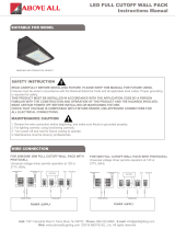
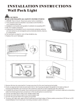
Page is loading ...

Add: 1501 Industrial Way N, Toms River, NJ 08755 Phone: 866-222-8866 E-mail: [email protected]
Web: www.aboveallLighting.com ©2016 ABOVE ALL. Inc. All rights reserved
VISION LED STRIP
Instructions Manual
1
READ CAREFULLY BEFORE INSTALLING FIXTURE. PLEASE KEEP THIS MANUAL FOR FUTURE USING.
Fixtures must be wired in accordance with the National Electrical Code and all applicable local codes. Proper
grounding is required for safety.
THIS PRODUCT MUST BE INSTALLED IN ACCORDANCE WITH THE APPLICATION CODE BY A PERSON
FAMILIAR WITH THE CONSTRUCTION AND OPERATION OF THE PRODUCT AND THE HAZARDS
INVOLVED.
MAKE CERTAIN POWER OFF BEFORE INSTALLING OR MAINTAINING FIXTURE.
CHECK THAT VOLTAGE IS COMPATIBLE WITH FIXTURE DRIVER, USE APPROVED CONNECTORS FOR
ALL ELECTRICAL CONNECTIONS.
WARNING:
SUITABLE FOR MODEL
WIRE CONNECTION
RISK OF ELECTRICALSHOCK
• Turn off electrical power at fuse or circuit breaker box before wiring xture to the power supply.
• Turn off the power when you perform any maintenance.
• Verify that supply voltage is correct by comparing it with the luminaire label information.
• Make all electrical and grounded connections in accordance with the National Electrical Code and any applicable
local code requirements.
• All wiring connections should be capped with UL approved wire connectors.
SAFETY INSTRUCTION:
CAUTION:
RISK OF INJURY
• Wear gloves and safety glasses at all times when removing luminaire from carton, installing, servicing or
performing maintenance.
• Avoid direct eye exposure to the light source while it is on.
• Account for small parts and destroy packing material, as these may be hazardous to children.
CAUTION:
RISK OF FIRE
• Keep combustible and other materials that can burn away from luminaire and lamp/lens.
• MIN 90°C SUPPLY CONDUCTORS.
WIRE CONNECTION
Universal voltage driver permits operation at 120V thru 277V, 347V, 50 or 60Hz
a. Connect the voltage supply Line to our AC-L lead
b. Connect the voltage Neutral supply to our AC-N lead
c. Connect the green/yellow ground lead to the supply ground lead

Add: 1501 Industrial Way N, Toms River, NJ 08755 Phone: 866-222-8866 E-mail: [email protected]
Web: www.aboveallLighting.com ©2016 ABOVE ALL. Inc. All rights reserved
VISION LED STRIP
Instructions Manual
2
INSTALLATION
ACCESSORY PACK
NUT X 3
PREPARATION
Locate the mounting points based on the Dimension Drawing.
120-277V / 347V
Fixture
Black
LINE
COMMON
GROUND
White
Green
3.15”
(80)
20.50”
(521)
15.75”
(400)
15.75”
(400)
36.0”
(915)
6.50”
(165)
9.50”
(241)
9.50”
(241)
24.0”
(610)
3.53”
(90)
4.65”
(118)
E=7/8”(22.5) K.O.
F=5/16x1/2”(8x12.5)K.O.
48.0”
(1220)
20.50”
(521)
1.38”
(35)
F
F
F F
F
F
E
E
E
E
E
E
4FT
3FT
2FT

Add: 1501 Industrial Way N, Toms River, NJ 08755 Phone: 866-222-8866 E-mail: [email protected]
Web: www.aboveallLighting.com ©2016 ABOVE ALL. Inc. All rights reserved
VISION LED STRIP
Instructions Manual
3
End Cap
Screw A
Lens
DC Wires
Housing
Gear Tray
Driver
AC Cord
Buckle
Buckle
Safety Cable
Screw Customer
Supplied
SURFACE MOUNT
1. Gently squeeze the housing to loosen the buckle between End Cap and Housing. Remove one End Cap and Lens.
2. Remove Screw A (4) and the Gear Tray. Take care of the LED in the process of operation.
3. Depending on structural conditions, secure luminaire to mounting surface by customer supplied anchor screws, toggle
bolts or suitable fasteners into Keyhole Slots.
4. Secure Gear Tray to luminaire base by locking the removed Screw A (4). Reattach Lens and the End Cap to luminaire.
5. Connect wires as shown in wiring diagram with wire nuts.
Notes: Make sure the safety ropes always are connected between luminaire base and Gear Tray.
QUICK SURFACE MOUNT
1. Drill holes according to following drill pattern.
2. Fix the Hanger Brackets (2) to ceiling or wall by appropriate fastener (customer supplied).
3. Push Side Knock Out Cover (4) inwards to open the side Knock Out Slots (4). See Figure 2.
4. Push the luminaire up into Hanger Brackets so that it snaps into Knock Out Slots. Fasten the Hanger Brackets with
supplied Bolts (2) and Nuts (2). See Figure 3.
5. Connect wires as shown in wiring diagram with wire nuts.
Notes: Hanger bracket need to be bought separately.
ø
0.25”
(
ø
6.4)
0.25”
(6.4)
3”
(76.2)
SIZE
2FT
3FT
4FT
L
19.0”(482.6mm)
31.5(800.0mm)
41.0”(1041.4mm)
Drill Pattern

Add: 1501 Industrial Way N, Toms River, NJ 08755 Phone: 866-222-8866 E-mail: [email protected]
Web: www.aboveallLighting.com ©2016 ABOVE ALL. Inc. All rights reserved
VISION LED STRIP
Instructions Manual
4
CHAIN MOUNT
1. Feed V-Clips (order separately) into holes of the luminarie base. See Figure 3.
2. Attach customer supplied Chain to the V-Clips and mounting surface. Make sure the luminarie is balanced.
3. Connect wires as shown in wiring diagram with wire nuts.
Side Knock Out
Side Knock Out Cover
Hanger Bracket
AC Cord
V-Clip
Knock Out Slots
Figure 1
Figure 2
Figure 3
Junction Box (By others)
3”
(76.2)
41.0”
(1041.4)
6.9”
(176.0)
41.0”
(1041.4)
8ft=4ft+4ft

Add: 1501 Industrial Way N, Toms River, NJ 08755 Phone: 866-222-8866 E-mail: [email protected]
Web: www.aboveallLighting.com ©2016 ABOVE ALL. Inc. All rights reserved
VISION LED STRIP
Instructions Manual
5
CONTINUOUS RUN MOUNT (REPLACE WITH 8FT LENS)
1. Gently squeeze the housing and remove End Caps and Lens.
2. Join and buckle two xtures together with continuous run mount bracket (order separately) and secure by screws (4).
3. Remove another End Cap and install a new 8ft Lens (ordered separately). Replace the removed End Cap again
Notes: Make sure the safety ropes always are connected between luminaire base and Gear Tray.
End Cap
End Cap
4FT Lens
Figure 1 Figure 3 Figure 4Figure 2
Housing
Screw
Bracket
8ft Lens
Bracket
MICROWAVE ON/OFF SENSOR SETTING
By selecting the combination on the DIP switch, sensor data can be precisely set for each specic application.
Detection area can be reduced by selecting the combination on the
DIP switches to t precisely each application.
Default Setting: 100%
Refers to the time period the lamp remains at 100% illumination after
no motion detected.
Default Setting: 20min
When set to “Const-ant ON”, the microwave sensor function is inactive,
lights turns on or off by switch.
When set to Sensor, the microwave sensor function is active.
Default Setting: Sensor
The sensor can be set to only allow the lamp to illuminate below a
dened ambient brightness threshold.
When set to Disable mode, the daylight sensor will switch on the lamp
when motion is detected regardless of ambient light level.
50lux, 25lux: twilight operation, 10lux, 2lux: darkness operation only.
Default Setting: Disable
Detection Area
Hold Time
Mode
Daylight Sensor

Add: 1501 Industrial Way N, Toms River, NJ 08755 Phone: 866-222-8866 E-mail: [email protected]
Web: www.aboveallLighting.com ©2016 ABOVE ALL. Inc. All rights reserved
VISION LED STRIP
Instructions Manual
6
Ref#: 13983-10521
MICROWAVE DIMMING SENSOR SETTING
Detection area
Detection area can be reduced by selecting the combination on the DIP switches to t
precisely each application .
Default Setting: 100%
By selecting the combination on the DIP switch, sensor data can be precisely set for each specic application.
Hold time
Refers to the time period the lamp remains at 100% illumination after no motion detected.
Default Setting: 20min
ON
ON
Stand-by period
Refers to the time period the lamp remains at a low light level before it completely
switches off in the long absence of people. When set to“ Disable”mode, the low light is
maintained until motion is detected
Default Setting: Disable
Daylight sensor
The sensor can be set to only allow the lamp to illuminate below a dened ambient
brightness threshold.
When set to Disable mode, the daylight sensor will switch on the lamp when motion is
detected regardless of ambient light level.
50lux, 30lux: twilight operation, 10lux, 5lux: darkness operation only.
Note that daylight sensor is active only when lamp totally switches off.
Default Setting: Disable
ON
Stand-by dimming level
The low light level you would like to have after the hold time in the long
absence of people.
Default Setting: 50%
/


