Page is loading ...

LED LEOPARD SERIES MINI FLOOD & WALL LIGHT
Instruction Manual
Add: 1501 Industrial Way N, Toms River, NJ 08755 Phone: 866-222-8866 E-mail: [email protected]
Web: www.AboveAllLighting.com ©2016 ABOVE ALL. Inc. All rights reserved
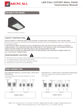
SUITABLE FOR MODEL
1
WIRE CONNECTION
INPUT VOLTAGE: 120-277V,120V,277V, NON-DIMMING
SAFETY INSTRUCTION
Maintenance Caution
READ CAREFULLY BEFORE INSTALLING FIXTURE.
PLEASE KEEP THIS MANUAL FOR FUTURE USE.
Fixtures must be wired in accordance with the National
Electrical Code and all applicable local codes. Proper
grounding is required for safety.
THIS PRODUCT MUST BE INSTALLED IN
ACCORDANCE WITH THE APPLICATION CODE BY
A PERSON FAMILIAR WITH THE CONSTRUCTION
AND OPERATION OF THE PRODUCT AND THE
HAZARDS INVOLVED.
MAKE CERTAIN POWER IS OFF BEFORE
INSTALLING OR MAINTAINING FIXTURE.
CHECK THAT VOLTAGE IS COMPATIBLE WITH
FIXTURE DRIVER. USE APPROVED CONNECTORS
FOR ALL ELECTRICAL CONNECTIONS.
1. Review the wire connection before beginning, and
make sure xture is grounded properly.
2. For lighting controls, follow control instructions
carefully.
3. Turn power off and wait for xture to cool before
performing maintenance.
4. Maintenance must be done by professionals.
Make the following Electrical Connection:
a) Connect the voltage supply line to ACL in black.
b) Connect the voltage supply Neutral to ACN in white
c) Connect green ground lead to the supply ground lead.
INPUT VOLTAGE: 120-277V,120V,277V, DIMMING
Make the following Electrical Connection:
a) Connect the voltage supply Line to ACL in Black.
b) Connect the voltage supply Neutral to ACN in White
c) Connect Green ground lead to the supply ground lead
d) Connect the supply positive dimming lead to Dim+ lead
in Red
e) Connect the supply negative dimming lead to Dim- lead
in Blue.
INSTALLATION
ITEMS REQUIRED
Accessory Pack Included:
Wire Nut x 3(Non-dimming) / 5(Dimming)
O-ring x 2
Tools Prepared by Customer:
Phillips screwdriver
Electrical wiring tools
Water tight cord connector
Bracket attachment hardware
Appropriate tools

LED LEOPARD SERIES MINI FLOOD & WALL LIGHT
Instruction Manual
Add: 1501 Industrial Way N, Toms River, NJ 08755 Phone: 866-222-8866 E-mail: [email protected]
Web: www.AboveAllLighting.com ©2016 ABOVE ALL. Inc. All rights reserved
2
Ref#: 11096-21013
OPTION 1: TRUNNION INSTALLATION
OPTION 2: KNUCKLE INSTALLATION
OPTION 3: JUNCTION BOX INSTALLATION
1. Mount luminaire to surface using the hole pattern
provided on the trunnion bracket. Recommend 1/4”-20
lag bolts and washers (supplied by others).
2.Make electrical connections from the trunnion cord to
the supply wiring as above wiring digram. Be sure to
use an appropriate weather-tight seal at the trunnion
cord entry point (not included.)
3.Adjust the aiming angle of the xture by loosening the
pivot screws and lock screws on the trunnion bracket
and rotating the assembly to the desired angle. Re-
tighten the pivot and lock screws to ensure that the
xture is not loose.
Body
Wire
M4*10 Screw
Trunnion
Waterproof Joint 1/2 NPS
1.Loosen the knuckle center screw. Adjust the position of
the knuckle stem. Re-tighten.
2.Route electrical leads through the 1/2” NPS access
hole in cover plate (supplied by others). Secure cover
plate to knuckle with lock nut.
3.Make electrical connections as above wiring digram.
4.Push wires into junction box and install cover plate
(with luminaire attached) to the junction box.
1.Open connection box, mount luminaire to wall by drilling
(2) holes on the junction box as Fig.2 shown
2.Make electrical connections in the connection box as
above wiring digram.
3.Screw the cover tightly
4.Adjust the direction of the body by loosening the pivot
screws on holder. Re-tighten the pivot and lock screws to
ensure that the xture is not loose.
Knuckle
Body
1/2 NPS Nut
Wire
Knuckle
center screw
Body
Wire
Holder
1/2 NPS Block
Connection Box
Waterproof Joint
Connection Box Cover
Fig. 1
Fig. 2
/


