Page is loading ...

Universal Voltage 40W, 60W, 80W permits operation at
120VAC thru 277VAC or 347VAC or 480VAC, 50 or 60 Hz.
Add: 1501 Industrial Way N, Toms River, NJ 08755 Phone: 866-222-8866 E-mail: [email protected]
Web: www.AboveAllLighting.com ©2016 ABOVE ALL Lighting, Inc. All rights reserved
SMT LED AREA LIGHT
Instructions Manual
1
SUITABLE FOR MODEL
WIRE CONNECTION
Make the following Electrical Connection:
a). Connect the voltage supply line to ACL in Black.
b). Connect the voltage supply Neutral to ACN in White.
c). Connect Green ground lead to the supply ground lead.
SAFETY INSTRUCTION
READ CAREFULLY BEFORE INSTALLING FIXTURE.
PLEASE KEEP THIS MANUAL FOR FUTURE USE.
Fixtures must be wired in accordance with the National
Electrical Code and all applicable local codes. Proper
grounding is required for safety.
THIS PRODUCT MUST BE INSTALLED IN
ACCORDANCE WITH THE APPLICATION CODE BY
A PERSON FAMILIAR WITH THE CONSTRUCTION
AND OPERATION OF THE PRODUCT AND THE
HAZARDS INVOLVED.
MAKE CERTAIN POWER IS OFF BEFORE
INSTALLING OR MAINTAINING FIXTURE.
CHECK THAT VOLTAGE IS COMPATIBLE WITH
FIXTURE DRIVER. USE APPROVED CONNECTORS
FOR ALL ELECTRICAL CONNECTIONS.
MAINTENANCE CAUTION
1. Review the wire connection before beginning, and
make sure xture is grounded properly.
2. For lighting controls, follow control instructions
carefully.
3. Turn power off and wait for xture to cool before
performing maintenance.
4. Maintenance must be done by professionals.
Note: If fxture is furnished with photocell receptacle,
please make sure install the photocell or shorting cap
INSTALLATION
ACCESSORY PACK
WIRE NUT X 3
PHOTOCELL X 1
SHORTING CAP X 1
WIRE NUT X 3
WIRE NUT X 3
WIRE NUT X 3 SCREW M6*18 X 4
SPRING WASHER M6 X 4
GASKET X 1
GASKET X 2
SCREW M8*30 X 2
SCREW M8*30 X 2
+
ROUND POLE
ADAPTER X 1
NUT M8 X 2
NUT M8 X 2
WARNING
Risk of injury or damage. Make certain
power is OFF before installing or maintaining
xture.
ACCESSORY PACK FOR SF AND TR
ACCESSORY PACK FOR PHOTOCELL
ACCESSORY PACK FOR 7 PIN
ACCESSORY PACK FOR SAR
ACCESSORY PACK FOR RAR
ACCESSORY PACK FOR WM
ACCESSORY PACK SHIPPED SEPARATE WITH
SKU#90204
1

Add: 1501 Industrial Way N, Toms River, NJ 08755 Phone: 866-222-8866 E-mail: [email protected]
Web: www.AboveAllLighting.com ©2016 ABOVE ALL Lighting, Inc. All rights reserved
SMT LED AREA LIGHT
Instructions Manual
2
Fig.1
1. Loosen (2) Screws on the Arm Door and open the
Door.
2. Feed Supply Wires through the center opening of
Pole (not supplied).
3. Insert one Bolt into Pole through the upper hole
along with Locking Washer, Washer, Gasket,
Adapter, Gasket and Nut but do NOT tighten.
4. Feed Supply Wires into Arm. Hung the Fixture on
the Bolt. Adjust the Fixture and thread the other bolt
through Locking Washer, Washer, Arm, Gasket,
Adapter, Gasket, Pole and Nuts. Then tighten both
Nuts. Make sure the Adapter is between two Gasket.
5. Make necessary wire connections inside the Arm and
knot wires for strain relief.
6. Replace the Arm Door and tighten the (2)Arm Door
Screws.
7. Secure Pole Top Cap (not supplied).
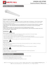
ROUND POLE ARM MOUNT (RAR)
Drill the pole according to the drill pattern Fig.1
NUT (2)
GASKET (2)
WAHSHER (2)
LOCKING WAHSHER (2)
ARM DOOR
BOLTS (2)
ADAPTER
BOLTS (2)
ARM DOOR
LOCKING WASHERS (2)
WASHERS (2)
WASHERS (2)
NUT(2)
GASKET
1. Loosen (2) Screws on the Arm Door and open the
Door.
2. Feed Supply Wires through the center opening of
Pole (not supplied).
3. Insert one Bolt into Pole through the upper hole
along with Locking Washer, Washer, Gasket and
Nut but do NOT tighten.
4. Feed Supply Wires into Arm. Hung the Fixture on
the Bolt. Adjust the Fixture and thread the other bolt
through Locking Washer, Washer, Arm, Gasket,
Pole, Washer and Nuts. Then tighten both Nuts.
Make sure the Gasket is between Arm and Pole.
5. Make necessary wire connections inside the Arm
and knot wires for strain relief.
6. Replace the Arm Door and tighten the (2)Arm Door
Screws.
7. Secure Pole Top Cap (not supplied).
SQUARE POLE ARM MOUNT (SAR)
Drill the pole according to the drill pattern Fig.1
2”
2”-2.25”
1.33”
0.354”
0.354”
0.625”
AR MOUNT DRILL PATTERN

Add: 1501 Industrial Way N, Toms River, NJ 08755 Phone: 866-222-8866 E-mail: [email protected]
Web: www.AboveAllLighting.com ©2016 ABOVE ALL Lighting, Inc. All rights reserved
SMT LED AREA LIGHT
Instructions Manual
3
TRUNNION MOUNT DRILL PATTERNTRUNNION MOUNT DRILL PATTERN
1. The sliptter ts a 2-3/8’’ O.D. Tenon. Make necessary
wire connections in the Sliptter and knot wires for
strain relief.
2. Place the sliptter over a tenon or pole and secure the
xture with (2) Set Screws on the side of the Sliptter.
3. Remove the Sliptter Cover Plate by removing (2)
screws on it. Then loosen the Locking Bolt and swivel
xture to a desired angle. The graduation on the
Sliptter Cover Plate can be used as guidelines to
adjust the angle.
4. Tighten the Locking Bolt and replace the Sliptter
Cover Plate with removed (2) screws.
SLIPFITTER MOUNT (SF)
SCREWS (2)
LOCKING BOLT
SET SCREW (2)
SLIPFITTER COVER PLATE
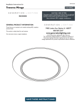
1. Install the trunnion to a desired bracketry by the center
hole using (2) Bolts, (2) Locking Washers and (2) Nuts
(not supplied) according to the Drill Pattern.
2. Adjust the angle of the xture by trunnion.
a. Loosen the (2) Center Bolts and (2) Angle Locking
Screws on the trunnion.
b. Swivel xture to a desired angle.
c. Tighten (2) Center Bolts and (2) Angle Locking Screws.
3. Feed Fixture Wires through the center opening of
Trunnion Bracket along with a Waterproof Bushing (not
supplied).
4. Make the necessary wire connections inside the
bracketry and knot wires for strain relief.
TRUNNION MOUNT (TR)
Drill the pole according to the drill pattern Fig.2
Fig.2
CENTER BOLT (2)
ANGLE LOCKING SCREW (2)

Add: 1501 Industrial Way N, Toms River, NJ 08755 Phone: 866-222-8866 E-mail: [email protected]
Web: www.AboveAllLighting.com ©2016 ABOVE ALL Lighting, Inc. All rights reserved
SMT LED AREA LIGHT
Instructions Manual
4
1. Support the xture to wall structure by customer
supplied support wire through the Support Wire Hole.
2. Make wire connection in the customer supplied
Embedded Junction Box.
3. Push all the wires into the Embedded Junction Box.
Secure the Wall Mount Bracket to the wall with Screw
M6*18 (4) and Spring Washer M6 (4).
Notes:
Make sure the waterproof treatments are done well when
making wiring and closing junction box.
Fig.3
EMBEDDED
JUNCTION BOX
(CUSTOMER
SUPPLIED)
SUPPORT WIRE
HOLE
SCREW M6*18 AND
SPRING WASHER M6 (4)
WALL MOUNT BRACKET
Ref#:20109-11217
Note: If xture is furnished with photocell
receptacle, install the photocell or shorting cap.
WALL MOUNT (WM)
Drill 4 mounting holes on the surface of wall according to
the drill pattern Fig.3. The aperture need to be suitable
for # 8-32 expansion screw.
/