Page is loading ...

MegaDySC Dynamic Voltage Sag Corrector
Bulletin Number 1608M—400 Amp Models sold after 1/1/2016
User Manual
Original Instructions

Important User Information
Read this document and the documents listed in the additional resources section about installation, configuration, and
operation of this equipment before you install, configure, operate, or maintain this product. Users are required to
familiarize themselves with installation and wiring instructions in addition to requirements of all applicable codes, laws,
and standards.
Activities including installation, adjustments, putting into service, use, assembly, disassembly, and maintenance are
required to be carried out by suitably trained personnel in accordance with applicable code of practice.
If this equipment is used in a manner not specified by the manufacturer, the protection provided by the equipment may
be impaired.
In no event will Rockwell Automation, Inc. be responsible or liable for indirect or consequential damages resulting from
the use or application of this equipment.
The examples and diagrams in this manual are included solely for illustrative purposes. Because of the many variables and
requirements associated with any particular installation, Rockwell Automation, Inc. cannot assume responsibility or
liability for actual use based on the examples and diagrams.
No patent liability is assumed by Rockwell Automation, Inc. with respect to use of information, circuits, equipment, or
software described in this manual.
Reproduction of the contents of this manual, in whole or in part, without written permission of Rockwell Automation,
Inc., is prohibited
Throughout this manual, when necessary, we use notes to make you aware of safety considerations.
Labels may also be on or inside the equipment to provide specific precautions.
WARNING: Identifies information about practices or circumstances that can cause an explosion in a hazardous
environment, which may lead to personal injury or death, property damage, or economic loss.
ATTENTION: Identifies information about practices or circumstances that can lead to personal injury or death, property
damage, or economic loss. Attentions help you identify a hazard, avoid a hazard, and recognize the consequence.
IMPORTANT Identifies information that is critical for successful application and understanding of the product.
SHOCK HAZARD: Labels may be on or inside the equipment, for example, a drive or motor, to alert people that dangerous
voltage may be present.
BURN HAZARD: Labels may be on or inside the equipment, for example, a drive or motor, to alert people that surfaces may
reach dangerous temperatures.
ARC FLASH HAZARD: Labels may be on or inside the equipment, for example, a motor control center, to alert people to
potential Arc Flash. Arc Flash will cause severe injury or death. Wear proper Personal Protective Equipment (PPE). Follow ALL
Regulatory requirements for safe work practices and for Personal Protective Equipment (PPE).

Rockwell Automation Publication 1608M-UM005A-EN-P - March 2016 3
Table of Contents
Preface Introduction. . . . . . . . . . . . . . . . . . . . . . . . . . . . . . . . . . . . . . . . . . . . . . . . . . . 5
Safety Considerations . . . . . . . . . . . . . . . . . . . . . . . . . . . . . . . . . . . . . . . . . . 5
Additional Resources . . . . . . . . . . . . . . . . . . . . . . . . . . . . . . . . . . . . . . . . . . . 6
Chapter 1
Installation System Components. . . . . . . . . . . . . . . . . . . . . . . . . . . . . . . . . . . . . . . . . . . . 7
System Layout . . . . . . . . . . . . . . . . . . . . . . . . . . . . . . . . . . . . . . . . . . . . . . . . . 8
System Clearance. . . . . . . . . . . . . . . . . . . . . . . . . . . . . . . . . . . . . . . . . . . . . . 10
System Mounting . . . . . . . . . . . . . . . . . . . . . . . . . . . . . . . . . . . . . . . . . . . . . 10
Electrical Interconnections . . . . . . . . . . . . . . . . . . . . . . . . . . . . . . . . . 11
Instructions For Energizing Loads Before Commissioning . . . . 12
MegaDySC System Installation Connections Checklist. . . . . . . 14
MegaDySC System Interconnections Checklist . . . . . . . . . . . . . . 14
Chapter 2
Communication Remote Diagnostics and Remote Bypass. . . . . . . . . . . . . . . . . . . . . . . . . 15
CBB Contacts (Bypass Circuit Breaker) . . . . . . . . . . . . . . . . . . . . . 15
CBI Contacts (Input Circuit Breaker). . . . . . . . . . . . . . . . . . . . . . . 15
Remote Seamless Bypass Command-EPO . . . . . . . . . . . . . . . . . . . 16
Contact Ratings . . . . . . . . . . . . . . . . . . . . . . . . . . . . . . . . . . . . . . . . . . . 16
MegaDySC Status Contacts . . . . . . . . . . . . . . . . . . . . . . . . . . . . . . . . 16
RS-232 Serial communication . . . . . . . . . . . . . . . . . . . . . . . . . . . . . . 16
i-Sense Voltage Monitor Communication . . . . . . . . . . . . . . . . . . . 17
Chapter 3
Applying Power
. . . . . . . . . . . . . . . . . . . . . . . . . . . . . . . . . . . . . . . . . . . . . . . . . . . . . . . . . . . . . . . . . . . .
19
Chapter 4
Operation System Description. . . . . . . . . . . . . . . . . . . . . . . . . . . . . . . . . . . . . . . . . . . . 21
MegaDySC System Operation. . . . . . . . . . . . . . . . . . . . . . . . . . . . . . . . . . 21
Automatic Bypass Switchboard Operation . . . . . . . . . . . . . . . . . . . . . . 22
Automatic Bypass Switchboard Operating Instructions. . . . . . . . . . . 23
Automatic System . . . . . . . . . . . . . . . . . . . . . . . . . . . . . . . . . . . . . . . . . 23
Manual Transfer to Maintenance Bypass (Bypass Mode). . . . . . 23
Manual Transfer to MegaDySC System (Normal Mode). . . . . . 23
Transient Voltage Surge Suppression. . . . . . . . . . . . . . . . . . . . . . . . . . . . 24
Troubleshooting Notes . . . . . . . . . . . . . . . . . . . . . . . . . . . . . . . . . . . . . . . . 25
Normal Mode . . . . . . . . . . . . . . . . . . . . . . . . . . . . . . . . . . . . . . . . . . . . . 25
Diagnostic Indicators . . . . . . . . . . . . . . . . . . . . . . . . . . . . . . . . . . . . . . 27
Chapter 5
Display Screen Overview . . . . . . . . . . . . . . . . . . . . . . . . . . . . . . . . . . . . . . . . . . . . . . . . . . . . . 29
Home Screen . . . . . . . . . . . . . . . . . . . . . . . . . . . . . . . . . . . . . . . . . . . . . . . . . 31
Mechanical Bypass. . . . . . . . . . . . . . . . . . . . . . . . . . . . . . . . . . . . . . . . . 31
System Status . . . . . . . . . . . . . . . . . . . . . . . . . . . . . . . . . . . . . . . . . . . . . . . . . 32

4 Rockwell Automation Publication 1608M-UM005A-EN-P - March 2016
Table of Contents
Voltage Sag Events . . . . . . . . . . . . . . . . . . . . . . . . . . . . . . . . . . . . . . . . . . . . 33
Voltage Sag Log . . . . . . . . . . . . . . . . . . . . . . . . . . . . . . . . . . . . . . . . . . . 33
Voltage Sag Detail . . . . . . . . . . . . . . . . . . . . . . . . . . . . . . . . . . . . . . . . . 34
Voltage Sag RMS Voltage Charts . . . . . . . . . . . . . . . . . . . . . . . . . . . 35
Voltage Sag Notification . . . . . . . . . . . . . . . . . . . . . . . . . . . . . . . . . . . 36
System Events. . . . . . . . . . . . . . . . . . . . . . . . . . . . . . . . . . . . . . . . . . . . . . . . . 36
System Event Log. . . . . . . . . . . . . . . . . . . . . . . . . . . . . . . . . . . . . . . . . . 36
System Event Detail . . . . . . . . . . . . . . . . . . . . . . . . . . . . . . . . . . . . . . . 37
System Event Notification . . . . . . . . . . . . . . . . . . . . . . . . . . . . . . . . . 39
System Configuration . . . . . . . . . . . . . . . . . . . . . . . . . . . . . . . . . . . . . . . . . 40
Model Information. . . . . . . . . . . . . . . . . . . . . . . . . . . . . . . . . . . . . . . . . . . . 40
Run System Tests. . . . . . . . . . . . . . . . . . . . . . . . . . . . . . . . . . . . . . . . . . 41
Diagnostics Mode . . . . . . . . . . . . . . . . . . . . . . . . . . . . . . . . . . . . . . . . . 41
Chapter 6
Maintenance Preventative Maintenance. . . . . . . . . . . . . . . . . . . . . . . . . . . . . . . . . . . . . . 43
Servicing . . . . . . . . . . . . . . . . . . . . . . . . . . . . . . . . . . . . . . . . . . . . . . . . . . . . . 46
Fuses . . . . . . . . . . . . . . . . . . . . . . . . . . . . . . . . . . . . . . . . . . . . . . . . . . . . . . . . . 46
Automatic Bypass Switchboard Fuses . . . . . . . . . . . . . . . . . . . . . . . 47
MegaDySC System and ER Cabinet Fuses . . . . . . . . . . . . . . . . . . . 47
Chapter 7
Specifications . . . . . . . . . . . . . . . . . . . . . . . . . . . . . . . . . . . . . . . . . . . . . . . . . . . . . . . . . . . . . . 49

Rockwell Automation Publication 1608M-UM005A-EN-P - March 2016 5
Preface
Introduction
The Allen-Bradley® Bulletin 1608M MegaDySC® Dynamic Sag Corrector is
engineered to provide years of voltage sag (dip) protection. The patented DySC®
technology does not use batteries, requires only routine maintenance, includes
three-stage transient voltage surge suppression, and has unparalleled energy
efficiency. Most electronic devices found in industry today are susceptible to
power disturbances. A momentary voltage sag in line voltage can reset or damage
sensitive production equipment. The MegaDySC system provides instantaneous
dynamic sag correction to help your equipment ride through these common
events. It connects normal utility power directly to the load until a voltage sag
occurs. During a sag, the MegaDySC inverter is activated-adding missing voltage
to keep the load voltage within the normal range. When utility power returns to
normal, the inverter is deactivated and the system is quickly ready to correct the
next sag.
The system reports these voltage sag events through its integrated touch screen
display and provides system status, voltage sag notification and history, runtime
statistics and system history in a simple and intuitive touch-based user interface.
Safety Considerations
The MegaDySC is designed to operate in industrial applications. Follow these
guidelines to verify that the safety and installation of the MegaDySC are handled
with appropriate care.
SHOCK HAZARD: The MegaDySC system has high voltage remaining up to 5
minutes after disconnection from the AC line. Touching exposed or
disconnected terminals, cables or parts can lead to serious injuries or even
death. Wait for a minimum of 5 minutes before performing any service or
testing after power is removed. High voltage remains if red LED indicators
above capacitor banks are lighted. Keep the cabinet doors closed and locked to
verify proper cooling airflow and to protect personnel from dangerous voltages
inside.
ATTENTION: - To reduce the risk of fire or electric shock, install in a
temperature and humidity controlled, indoor environment, free of conductive
contaminants.
• Avoid installing directly near heat-emitting equipment such as ovens, heaters, or furnaces.
• Ambient temperature must not exceed 40°C (104°F).
• Do not operate near water or excessive humidity (95% max).
• When punching or drilling holes for conduit fittings, take care to avoid dropping metallic particles
inside the enclosure as this can result in electrical damage.
• The system is not intended for outdoor use.
• The operating environment should be maintained within the parameters stated in this manual.
• Only authorized service personnel should perform service.
• Verify all power is disconnected before performing installation or service.

6 Rockwell Automation Publication 1608M-UM005A-EN-P - March 2016
Preface
Additional Resources
These documents contain additional information concerning related products
from Rockwell Automation.
You can view or download publications at
http:/www.rockwellautomation.com/literature/
. To order paper copies of
technical documentation, contact your local Allen-Bradley distributor or
Rockwell Automation sales representative.
ATTENTION: Internal components can be easily damaged by electrostatic
discharge (ESD). Do not touch circuit boards or electronic components with
hands or metal objects. The MegaDySC system is not rated to directly power life
support equipment.
• Verify the surrounding area is clean and uncluttered.
• Observe all DANGER, CAUTION, and WARNING notices affixed to the inside and outside of the
equipment.
ATTENTION: A tip over hazard exists. To guard against death, serious personal
injury, and/or equipment damage do not allow Automatic Bypass Switchboard
to tip beyond 10 degrees in any orientation during unloading and installation.
Resource Description
Bulletin 1608M MegaDySC Dynamic Voltage Sag Corrector,
publication 1608M-IN002
Basic information to install and apply power to corrector, also
includes specifications.
Industrial Automation Wiring and Grounding Guidelines,
publication 1770-4.1
Provides general guidelines for installing a Rockwell
Automation industrial system.
Product Certifications website, http://www.ab.com Provides declarations of conformity, certificates, and
other certification details.

Rockwell Automation Publication 1608M-UM005A-EN-P - March 2016 7
Chapter 1
Installation
System Components
The MegaDySC™ system consists of two enclosures including one “DySC™ 400 A Module”
MegaDySC section and one Automatic Bypass Switchboard, which is shipped separately and
must be mechanically and electrically interconnected at the time of installation. The MegaDySC
section houses the static bypass and voltage sag-correction electronics as well as the optional
extended-run (ER) module. The Automatic Bypass Switchboard houses the maintenance bypass
circuit breaker (CBB), the MegaDySC input (CBI) and output (CBO) circuit breakers,
automatic controls, and the i-Sense® voltage-monitoring sensor. This document applies to the
following MegaDySC System Models.
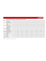
Table 1 - 400 A MegaDySC System Models
Catalog Number Voltage Rating 3 / 4-wire SR / ER
1608M-400A380V3S
380V
3
SR
1608M-400A380V3E ER
1608M-400A380V4S
4
SR
1608M-400A380V4E ER
1608M-400A400V3S
400V
3
SR
1608M-400A400V3E ER
1608M-400A400V4S
4
SR
1608M-400A400V4E ER
1608M-400A415V3S
415V
3
SR
1608M-400A415V3E ER
1608M-400A415V4S
4
SR
1608M-400A415V4E ER
1608M-400A460V3S
460V
3
SR
1608M-400A460V3E ER
1608M-400A460V4S
4
SR
1608M-400A460V4E ER
1608M-400A480V3S
480V
3
SR
1608M-400A480V3E ER
1608M-400A480V4S
4
SR
1608M-400A480V4E ER

8 Rockwell Automation Publication 1608M-UM005A-EN-P - March 2016
Chapter 1 Installation
System Layout
Figure 1 - Standard Run (SR) System Layout
12$'',7,21$/
&/($5$1&(
$%29(723
2)81,7,6
5(48,5(')25
,167$//$7,21
6:,7&+%2$5'
,167$//$7,21
5,*+76,'(
&/($5$1&(
&/($5$1&(
$'\6&
12$'',7,21$/
%$&.6,'(
%<3$66
,167$//$7,21
5(48,5(')25
5(48,5(')25
$8720$7,&
12$'',7,21$/
)5217$&&(66
,65(48,5(')25
,167$//$7,21
$1':,5,1*
$'')25
'2256:,1*
&/($5$1&(
[mm] in.
[mm] in.

Rockwell Automation Publication 1608M-UM005A-EN-P - March 2016 9
Installation Chapter 1
Figure 2 - Extended Run (ER) System Layout
12$'',7,21$/
&/($5$1&(
$%29(723
2)81,7,6
5(48,5(')25
,167$//$7,21
(5
(;7(1'('
581
5,*+76,'(
5(48,5(')25
&/($5$1&(
5(48,5(')25
02'8/(
12$'',7,21$/
%$&.6,'(
&/($5$1&(
6:,7&+%2$5'
,167$//$7,21
,167$//$7,21
$'\6&
%<3$66
$8720$7,&
12$'',7,21$/
)5217$&&(66
,65(48,5(')25
,167$//$7,21
$1':,5,1*
$'')25
'2256:,1*
&/($5$1&(
[mm] in.
[mm] in.

10 Rockwell Automation Publication 1608M-UM005A-EN-P - March 2016
Chapter 1 Installation
System Clearance
The MegaDySC doors are hinged on the left, and clearance must be given to
allow the door to swing open 90 degrees to the front of the enclosure.
Clearance for the Automatic Bypass switchboard must allow the front panels
to swing (left side hinged) open 90 degrees to the front of its enclosure.
Only front side access to the Automatic Bypass switchboard will be required
during installation wiring and cabinet interconnect wiring.
System Mounting
The MegaDySC system is floor-mounted, and should be secured using the
0.63” diameter mounting holes provided along the bottom channels. The
MegaDySC section is provided with all necessary interconnect wiring to the
Automatic Bypass switchboard section. Proper line-up is critical: The
MegaDySC section must be to the right of the Automatic Bypass section when
viewed from the front of the system.
The DySC 400A Module MegaDySC section is shipped separately from the
Automatic Bypass switchboard. It must be secured to the Automatic Bypass
enclosure with the 3/8” hardware supplied. See Figure 3
for fastening locations
and hardware arrangement. The optional ER enclosure is permanently
connected to the MegaDySC section prior to shipment.
Figure 3 - System Mounting
Attach the MegaDySC section to the Automatic Bypass
switchboard using the six sets of 3/8” hardware supplied.
• Install three sets along the front door frame and three sets
along the rear frame. Hardware along the rear frame can be
omitted if rear access to the switchboard is not available: it
is necessary to remove the rear panel of the switchboard to
install the rear sets of hardware.
• Install bolts from the switchboard side and thread into the
weld nuts in the MegaDySC section enclosure.
• Each set consists of one 3/8-16 x 1.0” bolt, one 3/8 split lock
washer and one 3/8” flat washer, assembled as shown.

Rockwell Automation Publication 1608M-UM005A-EN-P - March 2016 11
Installation Chapter 1
Figure 4 - Floor Mounting Detail
Electrical Interconnections
The MegaDySC cabinet and the Automatic Bypass (ABP) Switchboard are shipped separately.
The customer is responsible for system mounting. All interconnecting power cables are provided
(shipped inside the ABP switchboard) and will be connected by a factory-trained technician
during commissioning. At installation the loose ends of the main cables will be routed through
the bushings in the side of the ABP switchboard and connected inside the MegaDySC cabinet to
the appropriately labeled terminals. A control wiring harness is also provided in the ABP and
must be connected to the MegaDySC cabinet. This cable harness is routed through two large
holes, one in the ABP cabinet and one in the MegaDySC cabinet, at the bottom front of the
cabinets. The harness is plugged into the associated terminal block in the lower, left corner of the
MegaDySC cabinet. Finally, the incoming electrical service and outgoing load cables are brought
in through the top (or bottom) of the ABP switchboard and connected to the appropriate bus
locations, as shown in Figure 6
. AC input is connected to the bus bar terminals labeled L1, L2,
L3 and the protected load is connected to the bus bar terminals labeled X1, X2, X3.
237,21
581
$'\6&
02'8/(
(5
(;7(1'('
$8720$7,&
%<3$66
6:,7&+%2$5'
(56<67(03/&6
656<67(03/&6
[mm] in.
ATTENTION: Equipment must be earth-grounded according to local and National Electrical
Codes. Failure to supply proper equipment grounding can result in electrical shock or death. All
interconnection wiring will be installed by a factory-trained technician during system
commissioning.

12 Rockwell Automation Publication 1608M-UM005A-EN-P - March 2016
Chapter 1 Installation
Instructions For Energizing Loads Before Commissioning
Figure 5 - Rear View of Automatic Bypass Switch Board
If the MegaDySC system must be installed and put into maintenance bypass mode before
commissioning, the installers should put the system enclosures in place as described in System
Mounting on page 10, then feed the loose ends of inter-cabinet cables from the switchboard into
the MegaDySC cabinet:
1. Route the INPUT power cables (labeled L1, L2, L3) through the top bushing in the
right-side wall of the switchboard, labeled ‘Input to DySC’
2. Route the OUTPUT power cables (X1, X2, X3) and Ground cable through the bottom
bushing labeled ‘Output from DySC’
3. Route the control cable harness from the lower front switchboard pan into the
MegaDySC section through the matching holes in the lower front side panels. Install the
3.5’ snap-in grommet so that it protrudes into the MegaDySC cabinet before routing the
harness. Plug the harness header into connector TB5 on the MegaDySC floor.
4. Lockout circuit breakers CBI and CBO in the Automatic Bypass Switchboard.
5. Install utility input and load output conductors.
6. Energize the switchboard.
The MegaDySC Touch Screen display will be active only if the control harness has been
plugged in on the MegaDySC side. If the screen is active then 120V AC is present at
several points within the MegaDySC enclosure.
7. Push the green CLOSE CBB button to energize loads.
The remaining interconnections and commissioning must be completed by factory-
trained technicians.
ATTENTION: 120V AC is present at several pins of the harness header when the switchboard is
energized.

Rockwell Automation Publication 1608M-UM005A-EN-P - March 2016 13
Installation Chapter 1
Figure 6 - Switchboard Terminations and Conduit Landing Areas
;&21'8,7(.2$&&(66
>@$&78$/
&21'8,7(175<5(*,21)25
87,/,7<,13872873875(029(723
3$1(/72'5,//$1'25381&+
(175<5(*,21,6)520)520
5($5)520/()7
$/7(51$7(%27720(175<
5(*,21)2587,/,7<,1387287387
,67+(6$0($67233$1(/
(;&(377+()/2253$1
,61275(029$%/(
87,/,7<,1387
;0&03(53+$6(
28738772
3527(&7('/2$'6
;0&03(53+$6(
:,5,1*$&&(669,(:
5($59,(:6+2:1
5($53$1(/65(029('
>PP@LQ
'(7$,/0(&+$1,&$/
7<3,&$/3/&6
+(; >@
:,5(0&0
72548(72OELQ>1P@
1(875$/
:,5(6<67(0621/<
'(7$,/0(&+$1,&$/
+(; >@
:,5(.&0,/
72548(72OELQ>1P@
6<67(0
*5281'6
'(7$,/0(&+$1,&$/
+(; >@
:,5(.&0,/
72548(72OELQ>1P@

14 Rockwell Automation Publication 1608M-UM005A-EN-P - March 2016
Chapter 1 Installation
MegaDySC System Installation Connections Checklist
• Connect the Automatic Bypass Switchboard ground bus to an Earth Ground in
accordance with the National Electrical Code and local codes.
• Connect the AC input (line) conductors to the terminals labeled ‘L1’, ‘L2’ and ‘L3’. The
set is labeled ‘UTILITY INPUT’. These terminals are left of the switchboard. See
Figure 6.
• Connect the AC output (load) conductors to the terminals labeled ‘X1’, ‘X2’ and ‘X3’.
The set is labeled ‘OUTPUT TO PROTECTED LOADS’. See Figure 6.
• For 4-wire models only: connect input and output Neutral (N) conductors to the
NEUTRAL bus bar. The input N connection is required for proper operation of 4-wire
models. Do not connect to the NEUTRAL bus bar in 3-wire models.
• Check all electrical terminations for properly torqued connections. See Figure 6.
• For i-Sense Communication: connect either an analog telephone line to RJ11 jack or
Ethernet cable to RJ45 jack. The RJ11 and RJ45 jacks are in the upper switchboard
compartment. They can be accessed through a
1" conduit knockout in the top of the cabinet. See Figure 6 and Refer to i-Sense Voltage
Monitor Communication on page 17.
MegaDySC System Interconnections Checklist
• Connect the Automatic Bypass (ABP) Switchboard-to-MegaDySC ground cable to the
vertical strut in the MegaDySC cabinet at the location labeled with the ground symbol.
• Connect line side cables from input circuit breaker (CBI) in the ABP Switchboard to
the MegaDySC section bus bars labeled RH1-L1, RH1-L2 and RH1-L3 respectively.
• Connect load side cables from the output circuit breaker (CBO) in the ABP
Switchboard to the MegaDySC section bus bars labeled RH1-X1, RH1-X2 and RH1-
X3 respectively.
• Plug the control cable from the ABP Switchboard into the MegaDySC cabinet.
IMPORTANT To be completed by factory-trained technician

Rockwell Automation Publication 1608M-UM005A-EN-P - March 2016 15
Chapter 2
Communication
Remote Diagnostics and
Remote Bypass
Relay dry contacts are available for remote monitoring of the state of the Bypass Circuit Breaker
CBB and the Input Circuit Breaker CBI shunt-trip condition (See Figure 7
). In addition, a
customer-supplied relay can be used to remotely command a Seamless Bypass operation, as
described in Automatic Bypass Switchboard Operation on page 22 These functions are available
from terminal block TB1 in the upper compartment of the bypass switchboard. See Figure 9 on
page 17 and Figure 6 on page 13 for recommended conduit entry location.
Figure 7 - Schematic Diagram - Status Relay Contacts
CBB Contacts (Bypass Circuit Breaker)
“Normal” position for the Bypass Breaker is defined as the breaker being OFF, or Open. As such,
the Normally Open contacts are open when the Breaker is open; the Normally Closed contacts
will open when the breaker is closed.
Example: Normal run: CBB will be Open; therefore TB1/8 will be electrically connected to
TB1/7.
CBI Contacts (Input Circuit Breaker)
Relay K1 activates on any input circuit breaker shunt-trip signal (‘CBI-ST’). Heatsink over-
temperature, cabinet over-temperature, SCR Failure, Blown-Fuse or Open-Door indicators will
all assert the CBI ST signal to open the input circuit breaker, removing power from the
MegaDySC system. When this signal is present, Relay K1 is activated and its Normally Open
contacts close. Note that this is not a position indicator for the CBI circuit breaker: the CBI ST
signal will be present for only one (1) second when the shunt-trip command is asserted. The
Input breaker CBI will not automatically reclose after any shunt trip operation; user intervention
is required to manually reset the system to operational status.
CBB
N/C
CBB
N/O
1
2
3
4
5
6
7
8
9
10
11
12
TB1
K1
CustomerSuppliedContact:
ClosetoCommandSeamlessBypass
MegaDySC Customer

16 Rockwell Automation Publication 1608M-UM005A-EN-P - March 2016
Chapter 2 Communication
Remote Seamless Bypass Command-EPO
A Normally Open PLC contact, relay contact, or Push Button contact can be connected
between TB1/11 and TB1/12. Contacts must be rated for at least 120V AC at 25 mA. Note
that 120V AC is present at TB1/12 when the switchboard is energized. Close the contact to
initiate an automatic seamless bypass operation: CBB will close, then CBI and CBO will open,
removing power from the MegaDySC cabinet; voltage sag correction will then be disabled.
This feature can be used as an Emergency Power Off (EPO) function for the MegaDySC
cabinet. Power to the output loads or output distribution panel, if present, will not be
interrupted. Note that the automatic bypass functionality requires that nominal AC power is
present at the switchboard input terminals.
Contact Ratings
The CBB auxiliary contacts (Terminals 7-9 of TB1) are rated 5 A @ 250V AC, 5A @ 24V DC.
The K1 contacts (Terminals 1-6 of TB1) are rated 12 A @ 250V AC, 12 A @ 30V DC.
MegaDySC Status Contacts
Three relay contacts indicate MegaDySC electronics status; refer to Figure 8. The contacts are
form A and close upon occurrence of the named event: (a) any SAG EVENT, when rms input
voltage drops below 88.5% of rated value; (b) OUTPUT OK, when output voltage remains
between 87% and 110%; and (c) a system ALARM event. These relay contacts are
rated 24V at 1 A.
For access, remove the small metal cover above the door of the MegaDySC section
• All wiring is to be Class 2, limited to 24V, AC or DC.
• Acceptable wire gauges range from 24 ...12 AWG (0.205...2.5 mm
2
).
• Tighten connections to 5 lb•in(0.6 N•m). A plug-in connector is provided to facilitate
wiring.
• For permanent installation of communication conductors, a standard conduit knockout
is on the cabinet top.A removable connector (plug) is provided to facilitate wiring. All
wiring is to be class 2, limited to 24 Volts, AC or DC. Acceptable wire gauges range from
24...12AWG (0.205...2.5 mm
2
). Torque connections to 5 lb•in (0.6 N•m)
RS-232 Serial communication
A DE-9 male connector is provided for remote communication. Contact Rockwell Automation
Technical Support for protocol details.
ATTENTION: Remove power from the DySC system prior to connecting any alarm notification
device. Access to the terminal contacts risks exposure to a potential arc flash and/or electrocution
hazard unless power to the switchboard is removed.

Rockwell Automation Publication 1608M-UM005A-EN-P - March 2016 17
Communication Chapter 2
Figure 8 - Serial Communication Port and MegaDySC Status Relay Contacts
i-Sense Voltage Monitor Communication
The i-Sense voltage monitor is on the bottom front of the bypass switchboard and is pre-wired to
monitor the MegaDySC input and output voltages. The i-Sense Ethernet and Modem
communication ports are internally connected to the RJ45 and RJ11 jacks, respectively, in the
upper compartment of the bypass switchboard. See Figure 6 on page 13
and Figure 9 on page 17
for conduit entry locations. A communication connection is required to enable i-Sense
monitoring. See publication 1608S-UM001 for more information.
Figure 9 - Communication Conduit Entrance view from within upper switchboard
compartment
MDFNVDFFHVVIURPDERYH
RSWLRQDO7%
&RQGXLWHQWU\IRU
&RQGXLWHQWU\IRU
L6HQVH&RPPXQLFDWLRQV
L6HQVHFRPPXQLFDWLRQV
7%

18 Rockwell Automation Publication 1608M-UM005A-EN-P - March 2016
Chapter 2 Communication
Notes:

Rockwell Automation Publication 1608M-UM005A-EN-P - March 2016 19
Chapter 3
Applying Power
• After installation make certain there are no metal filings or any
conductive debris in or on any components inside the cabinets.
• Verify MegaDySC system voltage rating matches AC source voltage.
• Verify all input and output terminations including Grounding have been
completed and properly tightened.
• Replace all covers. Close and lock all cabinet and switchboard doors.
• Allow commissioning technicians to complete connections and initial
checks.
• Apply power from the upstream branch protection device when
instructed to do so by the commissioning technicians.
• After commissioning, follow instructions on the Automatic Bypass
switchboard to put the system into Normal mode. The load is now being
protected by the MegaDySC. The display should show “OK” in the
upper left corner
• Cycling input power in the sequence OFF--ON--OFF--ON within a
one minute period will cause a ‘Limit Cycle Timeout’ alarm. In such a
case sag correction will be disabled for one minute, after which the alarm
will automatically reset.
• Push Button ‘Close CBI’ is disabled for one minute after CBI is opened
for any reason.
ATTENTION: The MegaDySC system must be commissioned by factory-trained
engineers. Do not energize the MegaDySC system until instructed to do so by
commissioning engineers. If the Automatic Bypass switchboard must be
installed and energized before commissioning, follow instructions below
Figure 5 on page 12
.
ATTENTION: The MegaDySC and (optional) ER cabinets are interlocked.
Opening cabinet doors while in the MegaDySC ‘normal’ mode will cause
immediate automatic bypass operation and subsequent loss of voltage sag
protection while in ‘maintenance bypass’ mode. Automatic Bypass
switchboard cabinet doors are not interlocked and should be kept locked to
avoid exposure to dangerous voltages.
ATTENTION: ATTENTION: For operation, display screen, and maintenance
information,see MegaDySC System Operation on page 21
.

20 Rockwell Automation Publication 1608M-UM005A-EN-P - March 2016
Chapter 3 Applying Power
Notes:
/