Page is loading ...

T24
ED-PM-TX103-EN-v04
Language: English (original)
USER INSTRUCTIONS
Transmitter: T24-TS01
Product brand name:
SUPRATEQ TW77

IMPORTANT! This product is built on base model T24-07.
IMPORTANT! This document is intended for T24 receivers with software version
SW0033-11v23 or higher.
©Tele-Radio i Lysekil AB
August Barks gata 30A
SE-421 32 Västra Frölunda
Sweden
Phone: +46 (0)31 748 54 60, Email: info@tele-radio.com

User instructions│T24│
CHAPTER 1: INTRODUCTION 4
1.1About this document 5
1.2About T24 transmitters 7
CHAPTER 2: SAFETY 9
2.1Warnings & restrictions 9
2.2Safety features 12
CHAPTER 3: TECHNICAL DATA 13
3.1System specifications 13
3.2Transmitter specifications 13
CHAPTER 4: PRODUCT GENERAL DESCRIPTION 15
4.1Transmitter dimensions 15
4.2Transmitter top view 16
4.3Transmitter bottom view 17
4.4Transmitter side views 18
4.5Display and display LEDS 19
4.6Side buttons 24
CHAPTER 5: STATUS AND ERROR INDICATIONS 25
5.1Display LEDs status and error codes 25
5.2Errorindications and messages 25
CHAPTER 6: OPERATION 26
6.1General information 26
6.2General navigation 26
6.3Start-up protection 27
6.4Functionality test 28
6.5Log the transmitter in to a receiver 29
6.6Start a session 30
6.7Log the transmitter out from a receiver 32
6.8Switch the transmitter off 32
6.9Advanced operation 32
CHAPTER 7: BATTERY 35
7.1Battery precautions 35
7.2Battery information 37
CHAPTER 8: WARRANTY, SERVICE, REPAIRS, AND MAINTENANCE 39
CHAPTER 9: REGULATORY INFORMATION 40
9.1Europe 40
9.2United Kingdom 40
9.3North America 41
9.4Japan 43
ANNEX A: INDEX 44
ED-PM-TX103-EN-v04 3

User instructions│T24│Chapter 1: Introduction
CHAPTER 1: INTRODUCTION
READ ALL INSTRUCTIONS AND WARNINGS CAREFULLY BEFORE OPERATING
THE PRODUCTS.
These User instructions have been published by Tele Radio and are not subject to
any guarantees. The User instructions may be withdrawn or revised by Tele Radio at
any time and without further notice. Corrections and updates will be added to the
latest version of the manual. Always download the User instructions from our
website, www.tele-radio.com, for the latest available version. Keep the safety
instructions for future reference.
Tele Radio's product range is composed of transmitters, receivers, and accessories
intended for use together as a system and Tele Radio remote controls are often
built into wider applications. This documentation is not intended to replace the
determination of suitability or reliability of the product for specific user
applications and should not be used for this purpose. It is the responsibility of any
such users or integrators to perform the appropriate and complete risk analysis,
evaluation and testing of the products with respect to the relevant specific
application or use. Tele Radio shall not be responsible or liable for misuse of the
information contained herein.
Always refer to the applicable local regulations for installation and safety
requirements relating to cranes, hoists, material handling applications, lifting
equipment, industrial machinery, and/or mobile hydraulic applications using Tele
Radio products, e.g.:
lapplicable local and industrial standards and requirements,
lapplicable occupational health and safety regulations,
lapplicable safety rules and procedures for the factory where the equipment
is being used,
luser and safety manuals or instructions of the manufacturer of the
equipment where Tele Radio remote control systems are installed.
Tele Radio User instructions do not include or address the specific instructions
and safety warnings of the end product manufacturer.
For battery precautions, see "7.1 Battery precautions".
Tele Radio products are covered by a warranty against material, construction, or
manufacturing faults. See "Chapter 8: Warranty, service, repairs, and maintenance".
4 ED-PM-TX103-EN-v04

User instructions│T24│Chapter 1: Introduction
1.1About this document
NOTE: SUPRATEQ TW77 is the brand name for Tele Radio T24 waist transmitters
described in this document.
T24 systems are mainly intended for the hydraulic and mobile equipment markets.
These systems are not standardized but customized and adapted to each
customer's needs. How the outputs are connected to control the object depends on
each specific installation and will not be covered in this document. For exact
details, see the technical documentation provided for your specific system.
Drawings, schematics and connection diagrams are unique and are also provided
together with the system. Images shown in this document may therefore not show
the exact position of buttons, paddles and are for illustrative purposes only.
Before operating the product, read the corresponding documentation carefully.
These User instructions cover general safety issues, main technical specifications,
standard operating instructions and battery information. Images shown in this
document are for illustrative purposes only.
Please report any error or omission in this document, as well as any improvement
or amendment suggestion to td@tele-radio.com.
1.1.1COPYRIGHT
Information in this document is subject to change without notice. No part of this
publication may be reproduced, stored in a retrieval system, or transmitted in any
form or by any means, electronic, photographic, mechanical (including
photocopying), recording or otherwise for any purpose other than the purchaser's
personal use without the written permission of Tele Radio.
ED-PM-TX103-EN-v04 5

User instructions│T24│Chapter 1: Introduction
1.1.2TERM AND SYMBOL DEFINITIONS
The capitalized terms and symbol used herein shall have the following meaning:
lWARNING: indicates a hazardous situation which, if not avoided, could result
in death or serious injury.
lCAUTION: indicates a hazardous situation which, if not avoided, will result in
minor or moderate injury.
lIMPORTANT: is used for information that requires special consideration.
lNOTE: is used to address practices not related to physical injury.
This symbol is used to call attention to safety messages that would be
assigned the signal words "WARNING"or "CAUTION".
6 ED-PM-TX103-EN-v04

User instructions│T24│Chapter 1: Introduction
1.2About T24 transmitters
NOTE: Standard models are pre-configured.
T24 transmitters have duplex communication and work in continuous mode.
There is one standard model available.
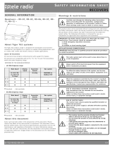
Model Front Stop button on
the side
M12 contact on
the side
LEDs in
handlebar
Cable
control
Vibration
motor
T24-TS01* 3 joysticks, 5
toggle switches ● ● ● ● ●
●Standard
*This product is built on base model T24-07.
ED-PM-TX103-EN-v04 7

User instructions│T24│Chapter 1: Introduction
1.2.1ERGONOMICS
Tele Radio transmitters are intended to
be used together with a Tele Radio
waist belt or neck strap, for better
support and improved ergonomics while
operating the transmitter.
Adjust the belt around the waist, then
hook the transmitter into the waist belt
straps.
Fig. 1Working position with a Tele Radio transmitter while using the Tele Radio
waist belt
NOTE: Always hold the transmitter with the control panel towards you. You must
be able to read any text on the control panel and understand the symbols on it.
1.2.2COMPATIBILITY
This transmitter is compatible with all transmitters and receivers in the Puma
range.
8 ED-PM-TX103-EN-v04

User instructions│T24│Chapter 2: Safety
CHAPTER 2: SAFETY
2.1Warnings & restrictions
Carefully read through the following safety instructions before
proceeding with the installation, configuration, operation, or
maintenance of the product. Failure to follow these warnings could
result in death or serious injury.
This product must not be operated without having read and understood the User
instructions, the specific technical documentation (for customized systems), and
having received the appropriate training. The purchaser of this product has been
instructed how to handle the system safely. The following information is intended
for use as a complement to applicable local regulations and standards.
IMPORTANT! Tele Radio remote controls are often built into wider applications.
These systems should be equipped with:
• a wired emergency stop where necessary
• a brake
• an audible or visual warning signal
2.1.1OPERATION
This radio system must not be used in areas where there is a risk of
explosion.
This equipment is not suitable for use in locations where children are
likely to be present.
Only qualified personnel should be permitted to access the transmitter
and operate the equipment.
ED-PM-TX103-EN-v04 9

User instructions│T24│Chapter 2: Safety
lAlways follow operating and maintenance instructions as well as all
applicable safety procedures and requirements.
lDo not open the receiver encapsulation unless you are qualified.
lYou must satisfy the age requirements in your country for operating
the equipment.
lIt is strictly prohibited to operate the equipment under the influence
of drugs, alcohol and/or medications.
lAlways test the transmitter stop button before operating it. Press
the stop button then twist and pull it out. This test should be done
on each shift.
lNever use a transmitter if the stop button is mechanically
damaged.Contact your supervisor or representative for service
immediately.
lNever leave the transmitter unattended.
lAlways switch the transmitter off when not in use. Store in a safe
place.
lKeep a clear view of the work area at all times.
10 ED-PM-TX103-EN-v04

User instructions│T24│Chapter 2: Safety
2.1.2MAINTENANCE
Before maintenance intervention on any remote controlled equipments:
• always remove all electrical power from the equipment.
• always follow lockout procedures.
lKeep the Safety information for future reference. Always download the User
instructions from our website, www.tele-radio.com, for the latest available
version.
lIf error messages are shown, it is very important to find out what caused
them. Contact your representative for assistance.
lThe functionality of the stop button should be tested at least after every 200
hours’ use (see "2.2.1 Stop button").
lIf the stop button is mechanically damaged, do not use the transmitter.
Contact your supervisor or representative for service immediately.
lKeep the product in a clean, dry place.
lDo not try to open the encapsulation.
lAlways contact your representative for service and maintenance work on the
product.
lKeep contacts and antennas clean.
lWipe off dust using a clean, slightly damp cloth.
lNever use cleaning solutions.
lCheck the encapsulation, foil and cable for damages every day. If the
encapsulation or foil is damaged, moisture can cause serious damage to the
electronics.
ED-PM-TX103-EN-v04 11

User instructions│T24│Chapter 2: Safety
2.2Safety features
2.2.1STOP BUTTON
When the Stop button is pressed, the stop relays on the
receiver deactivate, unless otherwise stated in the
corresponding technical documentation provided with each
customized system.
Fig. 1Example of possible locations for the stop button. Here on the right side of a
T24 transmitter.
IMPORTANT! The Stop button should always be tested before operating the
transmitter. This test should be done on each shift.
To test the stop button:
1. Press the Stop button.
2. Twist and release the Stop button.
12 ED-PM-TX103-EN-v04

User instructions│T24│Chapter 3: Technical data
CHAPTER 3: TECHNICAL DATA
NOTE: The information below may differ in customized systems, please refer to
the corresponding technical documentation provided with each system.
3.1System specifications
Radio frequency band 2405 – 2480MHz
Frequency management Direct Sequence Spread Spectrum (DSSS)
Field Strength Adaptation Feature
Number of Channels 16 (channel 11 – 26)
Range (typical) 100 m (328 ft), adjustable depending on configuration
System address 32 bit – 4294967295 possibilities
Data format 250 kbit/s
Hamming distance 6
Pairing (registration) Easy to pair without tools and without opening the
receiver housing.
Configuration Display menu
3.2Transmitter specifications
3.2.1COMMON SPECIFICATIONS
T24
Power supply Two (2), replaceable, rechargeable lithium-ion batteries
Battery pack 3.7V / 1600mAh Li-ion – 2 battery compartments
Hot swappable, RFID recognition
Current consumption From 150mA (depending on the configuration)
Operating time Up to 10h with one battery (depending on the
configuration)
Radio frequency output
power EIRP1< 12.5dBm (18mW)
Antenna Internal (external as an option)
Functions Up to 40 analog functions
Up to 144 (8 x 18) digital functions
Display LCD 2.2" TFT, color display
6-bit / 262,144 colors
Active area 45x33.8mm (1.77x1.33in)
Resolution: 320 x 240(RGB) px, QVGA
Graphic / pixels with backlight
Standard and custom configurations
Safety levels EN61508 SIL 3, EN ISO13849-1,PLe CAT3 (Stop function).
1Equivalent isotropic radiated power
ED-PM-TX103-EN-v04 13

User instructions│T24│Chapter 3: Technical data
T24
IP code IP65
Operating temperature -20…+55°C / -4…+130°F
Storage temperature -30…+70°C / -22…+158°F (without battery)1
Charging temperature +10…+35 °C / +50…+95 °F
3.2.2OTHER SPECIFICATIONS
T24-TS01
Number of joysticks 3, 2-axis with spring return for analog control
directions2.
Number of paddles –
Number of switches 2 x toggle switch 1-0 (maintained)
2 x maintained toggle switch 1-0-1 (maintained)
1 x toggle switch 1/0/1 (spring return)
Stop button On the side
Key switch –
LEDs in handlebar ●
RFID ○
Vibration motor for Haptic
feedback
●
Built-in drop and tilt
protection
●
Cable backup ●
Weight (typical) ~2kg (~4.4lbs)
●Standard ○Optional3– : Not available
Joystick directions
T24-TS01 transmitter has three joysticks (2-axis with spring-to-centre) allowing a
stepless control.
T24-TS01 Analog XY
Joystick 1 (XY) Analog XY The joystick operates
on both X and Y axes
with stepless
movement from the
center.
Joystick 2 (XY) Analog XY
Joystick 3 (XY) Analog XY
1For storage temperature of battery pack M245060 (D4-02), see "7.2 Battery information".
2see "Joystick directions" on next page.
3Must be purchased separately.
14 ED-PM-TX103-EN-v04

User instructions│T24│Chapter 4: Product general description
CHAPTER 4: PRODUCT GENERAL DESCRIPTION
NOTE: The pictures shown in this chapter are for illustrative purposes only.
Depending on the configuration, the actual product appearance may differ from
the basic model used for reference.
4.1Transmitter dimensions
ED-PM-TX103-EN-v04 15

User instructions│T24│Chapter 4: Product general description
4.2Transmitter top view
4.2.1T24-TS01
1. Joystick 1 (proportional XY)
2. Joystick 2 (proportional XY)
3. Joystick 3 (proportional XY)
4. Toggle switch SW1 (1–0
maintained)
5. Toggle switch SW3 (1–0–1 maintained)
6. Toggle switch SW2 (1/0/1 spring
return)
7. Toggle switch SW4 (1–0–1 maintained)
8. Toggle switch SW5 (1–0 maintained)
16 ED-PM-TX103-EN-v04

User instructions│T24│Chapter 4: Product general description
4.3Transmitter bottom view
4.3.1T24-TS01
1. M12 connector
2. RFID antenna (not
implemented)
3. Belt loops
4. Battery compartments 1 and 2
5. Memory card socket (not implemented)
6. Stop button
7. Product label
8. Replaceable batteries
ED-PM-TX103-EN-v04 17

User instructions│T24│Chapter 4: Product general description
4.4Transmitter side views
4.4.1T24-TS01
Left side Right side
1. Handlebar1
2. Joysticks 1–3
3. Toggle switches 1–5
4. Belt loops
5. SB1
6. SBX1
7. M12 connector
8. SB2
9. SB4
10. SBX2
11. Stop button
12. SB3
1With integrated LEDs.
18 ED-PM-TX103-EN-v04

User instructions│T24│Chapter 4: Product general description
4.5Display and display LEDS
The transmitter is equipped with three LEDs providing information about battery
levels, radio link status and other status (see "4.5.2 Display LEDs").
The transmitter display is intended for receiving and visualizing feedback
information from the system as well as for basic configuration. The T24 transmitter
display has two Function buttons (Select and Back) and two Navigation buttons (Up
and Down).
1. Back button
2. Select button
3. Battery LED1
4. Status LED
5. Battery LED 2
6. Up button
7. Down button
ED-PM-TX103-EN-v04 19

User instructions│T24│Chapter 4: Product general description
4.5.1STANDARD DISPLAY
Status and information symbols
NOTE: Applies only to -TS models.
1. Current channel number
2. RF signal power
3. Analog input indication
4. RF signal power
5. Battery level & battery number
6. Low battery 1
7. Low battery 2 (T24-TS01 only)
8. Handlebar LEDs ON (faceplate
illumination)
9. Flashlight ON (T24-TS01 only)
10. The receiver is used as CAN bus
node
11. Alarm muted
12. Digital input indication (DigIn1)
13. Digital input indication (DigIn2)
Turn the display on/off
Pressing side button SB3 for 2 seconds, will turn off the display.
NOTE: If the display is turned off, all alarms will be canceled (Mute mode).
The display can be turned on by pressing side button SB3 again (Mute mode
disabled).
20 ED-PM-TX103-EN-v04
/