Page is loading ...

SA F E T Y I N F O R M A T I O N S H E E T
RECEIVERS
GENERAL INFORMATION
Receivers – R9-01, R9-02, R9-06, R9-07, R9-
11, R9-12 –
About Tiger TG2 systems
The Tiger TG2 product range is composed of transmitters and receivers
intended for use together as a system in complex lifting applications such
as cranes, OHT cranes and electric hoists or mobile applications.
ABOUT R9 RECEIVERS
R9 receivers have simplex communication with support for duplex.
R9 receivers are compatible with all T9, T11, T12, T14 and T15 transmitters
within the same frequency range.
OVERVIEW OF THE AVAILABLE MODELS
- 433 MHz frequency range
Main board Display
board Expansion
boards Bus system
12–210 V DC,
24–230 V AC
12 relays
16-relay PROFIBUS or
Modbus/TCP
R9-01 ● ● – –
R9-06 ● ● –●
R9-11 ● ● ● –
●Standard – Not available
- 915 MHz frequency range
Main board Display
board Expansion
boards Bus system
12–210 V DC,
24–230 V AC
12 relays
16-relay PROFIBUS or
Modbus/TCP
R9-02 ● ● – –
R9-07 ● ● –●
R9-12 ● ● ● –
●Standard – Not available
About this document
Every care has been taken in the preparation of this document. Please
inform Tele Radio of any inaccuracies or omissions. This document covers
general safety issues, main technical specifications, guarantee, service and
maintenance, and regulatory information. For more information, please
refer to the Enduser instructions and the Installation instructions available
on www.tele-radio.com. Images shown in this document are for illustrative
purposes only.
Warnings & restrictions
Carefully read through the following safety instructions
before proceeding with the installation, configuration,
operation, or maintenance of the product. Failure to follow
these warnings could result in death or serious injury.
This product must not be operated without having read and understood
the Safety information sheet and having received the appropriate training.
The purchaser of this product has been instructed how to handle the
system safely. The following information is intended for use as a
complement to applicable local regulations and standards.
IMPORTANT! Tele Radio remote controls are often built into wider
applications. These systems should be equipped with:
• a wired emergency stop where necessary
• a brake
• an audible or visual warning signal
INSTALLATION AND COMMISSIONING
IMPORTANT! Only licensed or qualified personnel should be permitted
to install the product.
This radio system must not be used in areas where there is
a risk of explosion.
Always switch off all electrical power from the equipment
before installation procedure.
To utilize the safety features of the system, use the stop
relays in the safety circuitry of the object/ equipment to be
controlled.
When the equipment controlled by the receiver's standard
relays is connected via the stop relays, make sure that the
maximum current through the stop relays is still within the
specifications. Contact your representative for assistance.
RISK OF UNINTENDED EQUIPMENT OPERATION
Only transmitters that are intended for use should be
registered in the receiver.
Failure to follow these instructions could result in death,
serious injury, or equipment damage.
RISK OF ELECTRIC SHOCK
The receiver must only be opened by qualified installers or
authorized personnel.
Make sure the power supply is switched off before opening
the receiver.
Failure to follow these instructions could result in death,
serious injury, or equipment damage.
lThe receiver must be securely attached and located
where it will not be hit by e.g. any moving parts.
lDo not install the product in areas affected by strong
vibrations
lCable glands and vent plugs must face downwards to
prevent water ingress.
lEnsure that the power supply is connected to the correct
terminals.
lEnsure that flexible cords and cables are not damaged
through friction or stress.
lDo not use damaged cables.
lEnsure cables and connectors do not hang loose.
SI-TG2-RX102-EN-v04 1/4

SA F E T Y I N F O R M A T I O N S H E E T
RECEIVERS
lThe receiver is designed to withstand normal weather conditions but
should be protected from extreme conditions.
lMount the receiver in a location where the LEDs are easily visible and
the buttons accessible.
lMake sure to install available accessories inside or on the receiver
before permanently installing the receiver. A permanent installation of
the product must include fuse protection of the equipment and cables
against short circuits.
OPERATION
This equipment is not suitable for use in locations where
children are likely to be present.
Only qualified personnel should be permitted to access the
transmitter and operate the equipment.
lMake sure that the user satisfies the age requirements in
your country for operating the equipment.
lMake sure that the user is not under the influence of
drugs, alcohol and medications.
lMake sure that the user knows and follows operating and
maintenance instructions as well as all applicable safety
procedures and requirements.
The user should:
lAlways test the transmitter stop button before operating
it.This test should be done on each shift, without a load.
lNever use a transmitter if the stop button is mechanically
damaged.Contact your supervisor or representative for
service immediately.
lNever leave the transmitter unattended.
lAlways switch the transmitter off when not in use. Store
in a safe place.
lKeep a clear view of the work area at all times.
MAINTENANCE
Before maintenance intervention on any remote controlled
equipments:
• always remove all electrical power from the equipment.
• always follow lockout procedures.
lKeep the safety information for future reference. Always download the
Safety information sheet from our website, www.tele-radio.com, for the
latest available version.
lIf error messages are shown, it is very important to find out what
caused them. Contact your representative for help.
lThe functionality of the stop button should be tested at least after
every 200 hours’ use.
lIf the stop button is mechanically damaged, do not use the transmitter.
Contact your supervisor or representative for service immediately.
lKeep contacts and antennas clean.
lWipe off dust using a clean, slightly damp cloth.
lNever use cleaning solutions.
lCheck the encapsulation, foils and cable for damages. If the
encapsulation or foil is damaged, moisture can cause serious damage to
the electronics.
Regulatory information
NOTE: Models including additional naming conventions:
Model Article names Additional naming conventions
R9 R9-01
R9-02
R9-06
R9-07
R9-11
R9-12
R00009-01, R9-1, TG-R9-1, TG-R9-01
R00009-02, R9-2, TG-R9-2, TG-R9-02
R00009-06, R9-6, TG-R9-6, TG-R9-06
R00009-07, R9-7, TG-R9-7, TG-R9-07
R00009-11, TG-R9-11
R00009-12, TG-R9-12
EUROPE
Applies to: R9-01, R9-06, R9-11
CE MARKING
Hereby, Tele-Radio i Lysekil AB, declares that the product(s)
listed above is/are in compliance with the Radio Equipment
Directive 2014/53/EU.
The latest version of the complete EU Declaration of
Conformity is available at the following website: www.tele-
radio.com.
WEEE DIRECTIVE
This symbol means that inoperative electrical and electronic
products must not be mixed with household waste.The
European Union has implemented a collection and recycling
system for which producers are responsible. For proper
treatment, recovery and recycling, please take this product
to a designated collection point.
NORTH AMERICA
Applies to: R9-02, R9-07, R9-12
FCC AND ICSTATEMENTS
FCC: This product is in compliance with Part 15 of the FCC rules.
IC: This product is in compliance with Industry Canada’s licence-exempt
RSSs.
The complete statements are included in the corresponding installation
instructions available on www.tele-radio.com.
FCC/IC LABEL PLACEMENT
The FCC/ IC label is placed on the radio module. The radio module is
fitted inside the receiver.
EAC
Applies to: R9-01, R9-06, R9-11
EAC STATEMENT (ДЕКЛАРАЦИЯ ЕАС)
This product is declared as compliant within Eurasian Economic Union
(EAC). EAC declaration is available on request.
PRODUCT DESCRIPTION
Receiver description
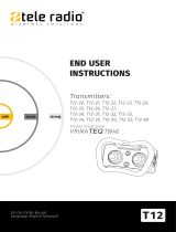
R9-01, R9-06, R9-11
1. Cable gland M25x1.5 2. BNC connectors for external antenna*
SI-TG2-RX102-EN-v04 2/4

SA F E T Y I N F O R M A T I O N S H E E T
RECEIVERS
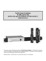
R9-02, R9-07, R9-12
1. Cable gland M25x1.5 2. RP-SMA connectors for external
antenna*
*Antenna in option. Must be purchased separately.
Mechanical installation
NOTE: For mounting on a wall or equipment, use 4 M5x30mm screws or
equivalent fastening method.
TECHNICAL DATA
Receiver specifications
NOTE: This product is permanently linked and will not use plug-in plug
connections. An appropriate disconnect device shall be provided as part
of the building installation1.
R9-01
R9-02 R9-06
R9-07 R9-11
R9-12
Input power212–210V DC (-15%/+20%); 24–230VAC (±10%), 50–
60Hz, max. 2A
Number of stop 2 (potential free*, 10A, 250VAC)3
1E.g. a circuit breaker or any equivalent means for disconnection according
to IEC 62368-1:2018.
2This product is permanently linked and will not use plug-in plug
connections. An appropriate disconnect device shall be provided as part of
the building installation.
3Maximum load is indicated for resistive load only.
R9-01
R9-02 R9-06
R9-07 R9-11
R9-12
relays
Number of relays 12 12 28
(potential free*, 10A, 250VAC)
Relay functionality Momentary, latching, interlocking
Number of digital
inputs 2 10
Number of transistor
outputs 1
Bus system – PROFIBUS or
Modbus/TCP** –
Radio communication Simplex (default), support for duplex
Max. number of
registered
transmitters
15
IP code IP66
Operating
temperature -20…+55°C / -4…+130°F
Safety level EN 61508 SIL3 and EN ISO 13849 PLe (Stop function)
Dimensions (LxWxH) 255x217 x81mm / 10.0x8.5x3.2in
Weight (typical) 1800g / 3.9lbs 1900g / 4lbs 2200g / 4.8lbs
Radio communication
R9-01, R9-06, R9-11 R9-02, R9-07, R9-12
Radio type Low IFtopology
Frequency band
(MHz) 433.075–434.775 903.0125–926.9875
Number of channels 69 (channels 1–69) –
Number of frequency
banks – 15 (banks 1–15)
Radio frequency
output power EIRP1: <10dBm (10mW) EIRP: <0dBm (1mW)
Antenna 2 BNC connectors for up
to 2 external antennas 2 RP-SMA connector for
up to 2 external
antennas
Current consumption
Input power R9-01, R9-02, R9-06, R9-07 R9-11, R9-12
Min.* Max.** Min.* Max.**
12 V AC – – – –
24 V AC 0.2 A 0.5 A 0.2 A 0.8 A
48 V AC 0.06 A 0.4 A 0.06 A 0.5 A
115 V AC 0.02 A 0.08 A 0.02 A 0.2 A
230 V AC 0.02 A 0.05 A 0.02 A 0.08 A
12 V DC 0.3 A 1.1 A 0.3 A 1.3 A
24 V DC 0.2 A 0.5 A 0.2 A 0.8 A
*Minimum current consumption = Receiver powered, no active relays, no
radio session established.
**Maximum current consumption = Receiver powered, all relays on the
receiver active, radio session established.
1Equivalent isotropic radiated power
SI-TG2-RX102-EN-v04 3/4

SA F E T Y I N F O R M A T I O N S H E E T
RECEIVERS
WARRANTY, SERVICE, REPAIRS, AND
MAINTENANCE
Tele Radio products are covered by a warranty against material,
construction and manufacturing faults. During the warranty period, Tele
Radio may replace the product or faulty parts. Work under warranty must be
performed by Tele Radio or by an authorized service center specified by
Tele Radio.
The following are not covered by the warranty:
lFaults resulting from normal wear and tear
lParts of a consumable nature
lProducts that have been subject to unauthorized modifications
lFaults resulting from incorrect installation and use
lDamp and water damage
Maintenance
lRepairs and maintenance must be performed by qualified personnel
lOnly use spare parts from Tele Radio
lContact your representative for service or any other assistance
lKeep the product in a clean, dry place
lKeep contacts and antennas clean
lWipe off dust using a slightly damp, clean cloth
lNOTE: Never use cleaning solutions or high-pressure washer.
Tele-Radio i Lysekil AB, Head office
Datavägen 21
SE-436 32 Askim
Sweden
Phone: +46 (0)31 748 54 60, Email: info@tele-radio.com
For more information about this product, please download the latest
Enduser instructions or Installation instructions from www.tele-radio.com.
SI-TG2-RX102-EN-v04 4/4
/