Page is loading ...

R21
ED-PM-RX103-EN-v04
Language: English (original)
USER INSTRUCTIONS
Receiver: R21-RS02

IMPORTANT! This product is built on base model R21-02.
IMPORTANT! This document is intended for R21 receivers with software version
SW0029-06v22 or higher.
©Tele-Radio i Lysekil AB
August Barks gata 30A
SE-421 32 Västra Frölunda
Sweden
Phone: +46 (0)31 748 54 60, Email: info@tele-radio.com

User instructions│R21│
CHAPTER 1: INTRODUCTION 4
1.1About this document 5
1.2About R21 receivers 6
CHAPTER 2: SAFETY 7
2.1Warnings & restrictions 7
CHAPTER 3: TECHNICAL DATA 10
3.1System specifications 10
3.2Receiver specifications 10
CHAPTER 4: PRODUCT GENERAL DESCRIPTION 13
4.1Receiver description 13
CHAPTER 5: STATUS AND ERROR INDICATIONS 14
5.1Receiver's status and error codes 14
5.2CANopen (DLEDs) run status 15
5.3CANopen(DLEDs) error status 15
5.4J1939 (DLEDs) run status 16
5.5J1939(DLEDs) error status 16
CHAPTER 6: OPERATION 17
6.1General information 17
6.2Register a transmitter in a receiver 17
6.3Log all transmitters out with the receiver 19
CHAPTER 7: BATTERY 20
7.1Battery precautions 20
7.2Battery information 21
CHAPTER 8: WARRANTY, SERVICE, REPAIRS, AND MAINTENANCE 22
CHAPTER 9: REGULATORY INFORMATION 23
9.1Europe 23
9.2United Kingdom 23
9.3North America 24
9.4Japan 27
ANNEX A: INDEX 28
ED-PM-RX103-EN-v04 3

User instructions│R21│Chapter 1: Introduction
CHAPTER 1: INTRODUCTION
READ ALL INSTRUCTIONS AND WARNINGS CAREFULLY BEFORE OPERATING
THE PRODUCTS.
These User instructions have been published by Tele Radio and are not subject to
any guarantees. The User instructions may be withdrawn or revised by Tele Radio at
any time and without further notice. Corrections and updates will be added to the
latest version of the manual. Always download the User instructions from our
website, www.tele-radio.com, for the latest available version. Keep the safety
instructions for future reference.
Tele Radio's product range is composed of transmitters, receivers, and accessories
intended for use together as a system and Tele Radio remote controls are often
built into wider applications. This documentation is not intended to replace the
determination of suitability or reliability of the product for specific user
applications and should not be used for this purpose. It is the responsibility of any
such users or integrators to perform the appropriate and complete risk analysis,
evaluation and testing of the products with respect to the relevant specific
application or use. Tele Radio shall not be responsible or liable for misuse of the
information contained herein.
Always refer to the applicable local regulations for installation and safety
requirements relating to cranes, hoists, material handling applications, lifting
equipment, industrial machinery, and/or mobile hydraulic applications using Tele
Radio products, e.g.:
lapplicable local and industrial standards and requirements,
lapplicable occupational health and safety regulations,
lapplicable safety rules and procedures for the factory where the equipment
is being used,
luser and safety manuals or instructions of the manufacturer of the
equipment where Tele Radio remote control systems are installed.
Tele Radio User instructions do not include or address the specific instructions
and safety warnings of the end product manufacturer.
Tele Radio products are covered by a warranty against material, construction, or
manufacturing faults. See "Chapter 8: Warranty, service, repairs, and maintenance".
4 ED-PM-RX103-EN-v04

User instructions│R21│Chapter 1: Introduction
1.1About this document
R21 systems are mainly intended for the hydraulic and mobile equipment markets.
These systems are not standardized but customized and adapted to each
customer's needs. How the outputs are connected to control the object depends on
each specific installation and will not be covered in this document. For exact
details, see the technical documentation provided for your specific system.
Drawings, schematics and connection diagrams are unique and are also provided
together with the system. Images shown in this document may therefore not show
the exact position of buttons, paddles and are for illustrative purposes only.
Before operating the product, read the corresponding documentation carefully.
These User instructions cover general safety issues, main technical specifications,
and standard operating instructions. Images shown in this document are for
illustrative purposes only.
Please report any error or omission in this document, as well as any improvement
or amendment suggestion to td@tele-radio.com.
1.1.1COPYRIGHT
Information in this document is subject to change without notice. No part of this
publication may be reproduced, stored in a retrieval system, or transmitted in any
form or by any means, electronic, photographic, mechanical (including
photocopying), recording or otherwise for any purpose other than the purchaser's
personal use without the written permission of Tele Radio.
1.1.2TERM AND SYMBOL DEFINITIONS
The capitalized terms and symbol used herein shall have the following meaning:
lWARNING: indicates a hazardous situation which, if not avoided, could result
in death or serious injury.
lCAUTION: indicates a hazardous situation which, if not avoided, will result in
minor or moderate injury.
lIMPORTANT: is used for information that requires special consideration.
lNOTE: is used to address practices not related to physical injury.
This symbol is used to call attention to safety messages that would be
assigned the signal words "WARNING"or "CAUTION".
ED-PM-RX103-EN-v04 5

User instructions│R21│Chapter 1: Introduction
1.2About R21 receivers
R21 receivers have duplex communication and work in continuous mode.
There is one standard model available, with two M12 connectors (one male, one
female) and female RP-SMA-K connector for external antenna. This product is built
on base model R21-02.
Model Connectors Base
board
Expansion boards
CAN RS485 A/D IOs 8-
relay
R21-RS02
M12 (one male,
one female) and
RP-SMA-K
(female)
●●
(1)
●
(1) ○ ○
●Standard ○Optional1– Not available
1.2.1COMPATIBILITY
This receiver is compatible with all transmitters and receivers in the Puma range.
1Must be purchased separately.
6 ED-PM-RX103-EN-v04

User instructions│R21│Chapter 2: Safety
CHAPTER 2: SAFETY
2.1Warnings & restrictions
Carefully read through the following safety instructions before
proceeding with the installation, configuration, operation, or
maintenance of the product. Failure to follow these warnings could
result in death or serious injury.
This product must not be operated without having read and understood the User
instructions, the specific technical documentation (for customized systems), and
having received the appropriate training. The purchaser of this product has been
instructed how to handle the system safely. The following information is intended
for use as a complement to applicable local regulations and standards.
IMPORTANT! Tele Radio remote controls are often built into wider applications.
These systems should be equipped with:
• a wired emergency stop where necessary
• a brake
• an audible or visual warning signal
2.1.1OPERATION
This radio system must not be used in areas where there is a risk of
explosion.
This equipment is not suitable for use in locations where children are
likely to be present.
Only qualified personnel should be permitted to access the transmitter
and operate the equipment.
ED-PM-RX103-EN-v04 7

User instructions│R21│Chapter 2: Safety
lAlways follow operating and maintenance instructions as well as all
applicable safety procedures and requirements.
lDo not open the receiver encapsulation unless you are qualified.
lYou must satisfy the age requirements in your country for operating
the equipment.
lIt is strictly prohibited to operate the equipment under the influence
of drugs, alcohol and/or medications.
lAlways test the transmitter stop button before operating it. Press
the stop button then twist and pull it out. This test should be done
on each shift.
lNever use a transmitter if the stop button is mechanically
damaged.Contact your supervisor or representative for service
immediately.
lNever leave the transmitter unattended.
lAlways switch the transmitter off when not in use. Store in a safe
place.
lKeep a clear view of the work area at all times.
2.1.2MAINTENANCE
Before maintenance intervention on any remote controlled equipments:
• always remove all electrical power from the equipment.
• always follow lockout procedures.
lKeep the Safety information for future reference. Always download the User
instructions from our website, www.tele-radio.com, for the latest available
version.
lIf error messages are shown, it is very important to find out what caused
them. Contact your representative for assistance.
lThe functionality of the stop button should be tested at least after every 200
hours’ use .
lIf the stop button is mechanically damaged, do not use the transmitter.
Contact your supervisor or representative for service immediately.
lDo not try to open the encapsulation.
lAlways contact your representative for service and maintenance work on the
product.
lKeep contacts and antennas clean.
lWipe off dust using a clean, slightly damp cloth.
lNever use cleaning solutions.
8 ED-PM-RX103-EN-v04

User instructions│R21│Chapter 2: Safety
lCheck the encapsulation, foil and cable for damages every day. If the
encapsulation or foil is damaged, moisture can cause serious damage to the
electronics.
ED-PM-RX103-EN-v04 9

User instructions│R21│Chapter 3: Technical data
CHAPTER 3: TECHNICAL DATA
NOTE: The information below may differ in customized systems, please refer to
the corresponding technical documentation provided with each system.
3.1System specifications
Radio frequency band 2405 – 2480MHz
Frequency management Direct Sequence Spread Spectrum (DSSS)
Field Strength Adaptation Feature
Number of Channels 16 (channel 11 – 26)
Range (typical) 100 m (328 ft), adjustable depending on configuration
System address 32 bit – 4294967295 possibilities
Data format 250 kbit/s
Hamming distance 6
Pairing (registration) Easy to pair without tools and without opening the
receiver housing.
Configuration Display menu
3.2Receiver specifications
3.2.1COMMON SPECIFICATIONS
R21
Supply voltage 12–24VDC (-50%…+35%), max. 7A
Number of stop relays
Max. resistive load 2, potential free1
6 A, 30 V DC
Available slots for expansion
boards 62
Number of logical digital inputs up to 4
Number of logical digital
outputs up to 2
Number of Safe I/Os 4x10A
Bus system/ com. protocols:
standard CAN (J1939 or CANopen)
1* Potential free means that a supply voltage is needed to get voltage out of a relay.
2E.g. I/Os expansion board (digital and/or analog) or 8-relay expansion board (NO/NC)
10 ED-PM-RX103-EN-v04

User instructions│R21│Chapter 3: Technical data
R21
optional RS485 (Modbus RTU)1
Secondary CAN (J1939 or CANopen).
NOTE: The two CAN ports can be used for both
CANopen and J1939 but only one CAN port at a
time can be used for CANopen, whereas J1939
can be run in parallel on both ports.
Radio communication Duplex
Radio frequency output power EIRP2< 12.5dBm (18mW)
Antenna Internal (external passive and active antennas as
an option)
Max. number of registered
transmitters 32
Data logger 64Mbit log memory
Backup battery33V Lithium (CR 2032X)
Power protection Built-in reverse polarity, overvoltage and
undervoltage protections
Fuse Self resetting
Safety levels EN61508 SIL 3, EN ISO13849-1,PLe CAT3 (Stop
function).
IP code IP65
Operating temperature -20…+55 °C / -4…+130 °F
Storage temperature -30…+80°C / -22…+176°F
Dimensions (LxWxH) 120x117 x 51mm / 4.7x4.6x2.0in
Weight (typical) 400g / 0.8 lbs
3.2.2OTHER SPECIFICATIONS
R21-S02
M12 connector4●
Internal antenna ●
External antenna ○
RP-SMA-K connector5●
Expansion boards: ●
CAN 1
RS485 1
1Modbus RS485 RTU is often unique and must be configured depending on the application/customer's
need, therefore no standard configuration is provided. Contact your representative for assistance.
2Equivalent isotropic radiated power
3For clock backup in case of power disruption/failure. See "7.2 Battery information"
4Male M12 connector for CAN. Female M12 connector for RS485/ active antenna.
5Female connector (impedance: 50 Ω).For external passive antenna.
ED-PM-RX103-EN-v04 11

User instructions│R21│Chapter 3: Technical data
R21-S02
8-Relay ○
A/D inputs/outputs ○
RFID ○
Cable backup ○
●Standard ○Optional1– : Not available
1Must be purchased separately.
12 ED-PM-RX103-EN-v04

User instructions│R21│Chapter 4: Product general description
CHAPTER 4: PRODUCT GENERAL DESCRIPTION
NOTE: The pictures shown in this chapter are for illustrative purposes only.
Depending on the configuration, the actual product appearance may differ from
the basic model used for reference.
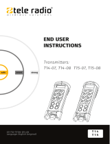
4.1Receiver description
1. Power cable gland (M20)
2. M12 male connector (CAN bus)
3. RP-SMA-K, female connector for
external antenna (impedance: 50
Ω)
4. M12 female connector (cable
control)
5. LED indicators
6. Capacitive sensor button (Cap
sensor button)
4.1.1LED INDICATORS
The receiver has a capacitive button including seven LEDs showing the receiver
status.
1. Status LEDs 1–5:
LED 1 (red): Registered transmitterand radio link
status
LED 2 (yellow): Transmitter login status
LED 3 (green): Not used
LED 4 (orange): Not used
LED 5 (blue): Not used
2. CAN status LEDs:
DLED 1: CAN interface 1
DLED 2: CAN interface 2
3. Capacitive sensor button (Cap sensor button)
ED-PM-RX103-EN-v04 13

User instructions│R21│Chapter 5: Status and error indications
CHAPTER 5: STATUS AND ERROR INDICATIONS
LEDs 1–5 indicate errors and status for the receiver, DLEDs 1–2 indicate errors and
status for CANopen.
5.1Receiver's status and error codes
LED Color Off On Flashing Indicates
1 red ●One or more transmitters is registered, radio
link established
○No transmitter is registered
●One or more transmitters is registered, no
radio link.
2 yellow ●One transmitter is logged in
○No transmitter is logged in
3 green – – – Not used
4 orange – – – Not used
5 blue – – – Not used
●LEDislit○LED is off
14 ED-PM-RX103-EN-v04

User instructions│R21│Chapter 5: Status and error indications
5.2CANopen (DLEDs) run status
DLED
color
On Flickering ( red/
green alternately)
Single flash Blinking
Green Operational
state LSS Stopped state Pre-operational
state
CANopen
communication state
Description
Operational State for process data transmission.
LSS LSSservices in progress.
Stopped Except for node guarding or heartbeat messages, a node
cannot transmit or receive any other messages in this
state.
Pre-operational State for the configuration of CANopen devices. PDO
communication is not possible in this state.
5.3CANopen (DLEDs) error status
DLED
color
On Flickering (red/
green alternately)
Single flash Double flash Triple flash
Red Bus off LSS Warning limit
reached Error control
event Sync error
Contact your representative for assistance.
ED-PM-RX103-EN-v04 15

User instructions│R21│Chapter 5: Status and error indications
5.4J1939 (DLEDs) run status
DLED color On Single flash
Green Operational No address
J1939 communication
state
Description
Operational Address claim is correct, processing messages.
No address Address claim is still running or has failed.
5.5J1939(DLEDs) error status
DLED color On Single flash
Red Bus off Warning limit reached
Contact your representative for assistance.
16 ED-PM-RX103-EN-v04

User instructions│R21│Chapter 6: Operation
CHAPTER 6: OPERATION
6.1General information
To control a receiver, the transmitter must be registered and logged in to the
receiver. If another transmitter is already logged in to the receiver, it must be
logged out before a different transmitter can be logged in.
More than one transmitter can be registered in the receiver, but only one
transmitter can be logged in at a time.
6.2Register a transmitter in a receiver
Registering means establishing communication between the transmitter and the
receiver.
R21 receivers can have up to 32 registered transmitters.
NOTE: The registration instructions require access to the receiver housing. For the
registration procedure to be successful, the receiver must be powered up.
RISK OF UNINTENDED EQUIPMENT OPERATION
Only transmitters that are intended for use should be registered in the
receiver.
Failure to follow these instructions could result in death, serious injury,
or equipment damage.
RISK OF UNINTENDED EQUIPMENT OPERATION
Do not perform this action when the receiver is in a session with another
transmitter. The radio communication may be interrupted or broken.
Failure to follow these instructions could result in death, serious injury,
or equipment damage.
ED-PM-RX103-EN-v04 17

User instructions│R21│Chapter 6: Operation
On the Receiver On the Transmitter
1. Power the receiver up.
LED 1 is flashing (red).
2. Press and hold the Cap sensor
button until LED1 stops flashing.
LEDs 2–5 flash (fast).
3. Release the Cap sensor button.
LEDs 1–5 flash (slow).
The receiver is now in registration
mode.
If no register command is received
within 30 seconds, the receiver
will exit registration mode.1
4. Make sure that the Stop button is
pressed.
5. Twist and release the Stop button.
The initial start-up logo is
displayed.Battery indicator(s) light
(s).The display shows:[Session
Selection].
6. Enter Menu mode(see
corresponding transmitter's
manual).
7. Navigate to the [Register] menu
using the Up/Down buttons.
8. Press the Select button to enter.
9. Choose a location for the receiver
to be registered in using the
Up/Down buttons.
10. Press the Select button to select.
A + sign is displayed in front of the
selected location.
11. Press the Back button to accept.
The display shows:[Registration
in progress…]
When the transmitter's register command is received, …
On the Receiver On the Transmitter
LEDs 1–5 flash (fast). The display shows:[Confirm
registration on the receiver].
The transmitter is now registered.
On the Receiver On the Transmitter
LED 1 is flashing (slow). The transmitter turns off.
If not successfully completed:
On the Receiver On the Transmitter
The receiver exits registration mode.
LED 1 is flashing (red). The display shows:[Registration
failed Timout]. The transmitter turns
off. Go back and proceed from step 2.
1It is also possible to exit registration mode by briefly touching the receiver's cap sensor button.
18 ED-PM-RX103-EN-v04

User instructions│R21│Chapter 6: Operation
6.3Log all transmitters out with the receiver
Logging out means stopping the communication between the transmitter and the
receiver.
NOTE: This logout option should be used when a lost or damaged transmitter
must be logged out from the receiver.
NOTE: If a transmitter has been lost or seriously damaged, use the replace
procedure on the transmitter whenever possible.
1. Press and hold the receiver Cap sensor button until LED2 stops flashing.
LED1 goes off, LED2 is lit, LEDs 3–5 keep flashing rapidly.
2. Release the Cap sensor button.
LEDs 1 and 5 flash slowly.
The logged in transmitter has been logged out. Any registered transmitter can
now log in.
ED-PM-RX103-EN-v04 19

User instructions│R21│Chapter 7: Battery
CHAPTER 7: BATTERY
7.1Battery precautions
Carefully read the following safety instructions and warnings before using or
disposing of the batteries.
Batteries contain flammable substances such as lithium or other organic
solvents, which may result in overheating, rupture or combustion.
Failure to read and follow the below instructions may result in fire,
personal injury and damage to property if charged or used improperly.
7.1.1HANDLING AND STORAGE
lDo not short-circuit, disassemble, deform or heat batteries.
lDo not use or charge the battery if it appears to be leaking,
deformed or damaged in any way.
lDo not solder directly onto batteries.
lStore in a cool location. Keep batteries away from direct sunlight,
high temperature, and high humidity.
lKeep batteries out of reach of small children. Should a child swallow
a battery, consult a physician immediately.
20 ED-PM-RX103-EN-v04
/