Tele Radio T26-TS02 Operating instructions
- Type
- Operating instructions
This manual is also suitable for
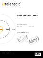
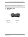
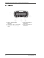
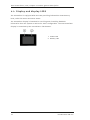
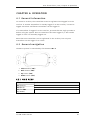
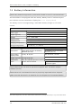
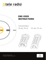
Below you will find brief information for T26-TS02, T26-TS03. These remote transmitters are designed for hydraulic and mobile equipment use. The T26-TS02 has two joysticks and four toggle switches. The T26-TS03 has six paddles and four toggle switches. Both models feature a stop button on the side, LEDs in the handlebar, vibration motor and cable backup. They have duplex communication, color display and are suitable for harsh environments. These devices can be used with other Tele Radio products.
Below you will find brief information for T26-TS02, T26-TS03. These remote transmitters are designed for hydraulic and mobile equipment use. The T26-TS02 has two joysticks and four toggle switches. The T26-TS03 has six paddles and four toggle switches. Both models feature a stop button on the side, LEDs in the handlebar, vibration motor and cable backup. They have duplex communication, color display and are suitable for harsh environments. These devices can be used with other Tele Radio products.


-
 1
1
-
 2
2
-
 3
3
-
 4
4
-
 5
5
-
 6
6
-
 7
7
-
 8
8
-
 9
9
-
 10
10
-
 11
11
-
 12
12
-
 13
13
-
 14
14
-
 15
15
-
 16
16
-
 17
17
-
 18
18
-
 19
19
-
 20
20
-
 21
21
-
 22
22
-
 23
23
-
 24
24
-
 25
25
-
 26
26
-
 27
27
-
 28
28
-
 29
29
-
 30
30
-
 31
31
-
 32
32
-
 33
33
-
 34
34
-
 35
35
-
 36
36
-
 37
37
-
 38
38
-
 39
39
-
 40
40
-
 41
41
-
 42
42
-
 43
43
-
 44
44
-
 45
45
-
 46
46


Tele Radio T26-TS02 Operating instructions
- Type
- Operating instructions
- This manual is also suitable for
Below you will find brief information for T26-TS02, T26-TS03. These remote transmitters are designed for hydraulic and mobile equipment use. The T26-TS02 has two joysticks and four toggle switches. The T26-TS03 has six paddles and four toggle switches. Both models feature a stop button on the side, LEDs in the handlebar, vibration motor and cable backup. They have duplex communication, color display and are suitable for harsh environments. These devices can be used with other Tele Radio products.
Ask a question and I''ll find the answer in the document
Finding information in a document is now easier with AI
Related papers
-
 Tele Radio T21 Operating instructions
-
 Tele Radio T19 Operating instructions
-
 Tele Radio R9-01 Installation guide
-
 Tele Radio T27-02 Operating instructions
-
 Tele Radio R8-11 Operating instructions
-
 Tele Radio TG-T15-8 Operating instructions
-
 Tele Radio T24-TS01 Operating instructions
-
 Tele Radio R21-RS02 Operating instructions
-
 Tele Radio TG-T12-31 Operating instructions
-
 Tele Radio TG-T9-2 Operating instructions


Other documents
-
turck TX107 Operating Instructions Manual
-
 YuTrax TX104 User manual
-
 MQ Multiquip T23-T26-T33 User manual
-
Mobicool X25 DC/AC User manual
-
Durabrand ADB2737BD User manual
-
Marantz DV4000/S1G User manual
-
Funai W4C-D4180DB User manual
-
Philips 32PFL3515D/F7 User manual
-
Alarm Lock NETWORXPANEL Installation Instructions Manual
-
Reloop MIXAGE User manual

