Page is loading ...

VISCAM 1000 System
Vehicle Imaging Subsystem
Document P/N: 10873
Document Version: D


Disclaimer iii
VISCAM 1000 Systems
Notice
The material contained in this manual consists of information that is proprietary to JAI Inc., and may only
be used by the purchasers of the product. JAI Inc. makes no warranty for the use of its product and
assumes no responsibility for any errors which may appear or for damages resulting from the use of the
information contained herein. JAI Inc. reserves the right to make changes without notice.
Microsoft Windows 8, Windows 7, Windows XP, Windows 2000, Windows 98, Windows NT, and Windows
Explorer are either registered trademarks or trademarks of Microsoft Corporation in the United States
and/or other countries.
Warranty
Each JAI product is warranted to be free from defects in material and workmanship under normal intended
use and service if installed in accordance with this manual. The standard warranty period for the VISCAM
1000 is 1 year (12 months) and begins on the date of shipment from JAI stock.
This warranty shall not apply to repairs or replacements necessitated by any cause beyond the control of
JAI, including but not limited to, 1) improper installation, 2) acts of nature, 3) accidents, 4) misuse, 5)
lack of proper maintenance, 6) unauthorized repairs or modifications.
Be advised, that you need to obtain an RMA number from JAI before returning units for warranty repair.

VISCAM 1000 Systems
iv Disclaimer
Certifications
CE Compliance
The VISCAM 1000 has been certified to conform to the requirements of Council Directive 89/336/EC for
electromagnetic compatibility and to comply with the following European Standards:
Emissions: EN 55022A: 2010/AC:2011
Immunity: EN 61000-4
All JAI products bearing the CE mark have been declared to be in conformance with the applicable EEC
Council Directives. However, certain factory-installed options or customer-requested modifications may
compromise electromagnetic compatibility and affect CE compliance. Please note that the use of
interconnect cables that are not properly grounded and shielded may affect CE compliance.
Contact JAI Applications Engineering Department for further information regarding CE compliance.
FCC
This equipment has been tested and found to comply with the limits for a Class A digital device, pursuant
to Part 15 of the FCC Rules. These limits are designed to provide reasonable protection against harmful
interference when the equipment is operated in a commercial environment. This equipment generates,
uses and can radiate radio frequency energy and, if not installed and used in accordance with the
instruction manual, may cause harmful interference to radio communications. Operation of this equipment
in a residential area may cause harmful interference, in which case the user will be required to correct the
interference at his own expense.
IP66
This equipment has been tested and found to comply with IP66. This proves that the equipment is resistant
to rain and dust in severe outdoor environments.
WARNING
Changes or modifications to this unit not expressly approved by the party responsible for FCC compliance
could void the user’s authority to operate the equipment.
September 28, 2015

Tables of Contents v
VISCAM 1000 Systems
Table of Contents
Disclaimer Notice ..................................................................................................... iii
Table of Contents ...................................................................................................... v
1 Introduction ............................................................................................... 1
1.1 Document Overview ..................................................................................... 1
1.2 Product Overview and System Hardware Components ............................................ 1
1.2.1 VISCAM 1000 System ..................................................................................... 2
1.2.2 External Traffic Light Sensor – TLS-301 (optional) ................................................. 2
1.2.3 External Light Sources .................................................................................. 2
1.2.4 Embedded Light Sources (LED-1000 IR, white or blue) ............................................ 2
1.2.5 VJP-300 Junction Panel ................................................................................. 2
1.2.6 Optional 24V DC Power Supply ........................................................................ 2
1.2.7 Optional gigabit Ethernet switch ..................................................................... 2
1.2.8 System interconnection cables ........................................................................ 2
1.3 VISCAM 1000 Product Line .............................................................................. 3
2 Preparing for installation ............................................................................... 4
2.1 Installation Preparation................................................................................. 4
2.2 Overhead Positioning .................................................................................... 4
2.3 Side of Road Installation ................................................................................ 6
3 Installing the VIS - Vehicle Imaging System ......................................................... 7
3.1 VIS Power Requirements ................................................................................ 7
3.1.1 Installing the VISCAM 1000 System.................................................................... 7
3.2 Installing the VJP-300 Junction Panel ................................................................ 9
3.2.1 Connection to VISCAM 1000 (X1 AND X2) ............................................................ 9
3.2.2 X6 Power Input Connector ........................................................................... 11
3.2.3 Trigger Input Connector (X14) ....................................................................... 11
3.3 Installing the TNL-50 .................................................................................. 12
4 System Set-Up .......................................................................................... 14
4.1 Pre-Alignment Checklist .............................................................................. 14
4.2 Select a Suitable Vehicle, License Plate, and Plate Stand for the Setup .................... 14
4.3 Connect the Setup Computer to the Camera ..................................................... 15
4.4 Drive and Park the Setup Vehicle Correctly ....................................................... 15
4.5 Perform Initial Lens Adjustment and Camera Aiming ........................................... 16
4.6 Perform Final Camera Mount and Lens Adjustments ............................................ 19
4.7 TNL-50 Flash Alignment and settings ............................................................... 21
4.7.1 TNL-50 Flash Settings ................................................................................. 22
4.8 LED-1000 Embedded Illuminator Setup ............................................................ 24
4.9 Trigger Mode Selection ............................................................................... 26
4.9.1 Trigger Synchronization Mode Selection ........................................................... 26
4.10 Automatic Triggering and Light Sensing Configuration .......................................... 27
4.10.1 Vehicle Detector Trigger Settings ................................................................... 27
4.10.2 Visualization helper for Vehicle Detector and ALC setup ....................................... 28
4.10.3 ADR settings in ALC mode ............................................................................ 29
4.11 High Dynamic Range Settings ........................................................................ 30
4.12 Time Synchronization Settings ...................................................................... 32
4.13 Solar Position Control for assisting the ALC ....................................................... 33
4.14 Video Streaming and Recording ..................................................................... 34
5 Appendix A: VISCAM 1000 Wiring Diagram ......................................................... 37
6 Appendix B: TLS-301 Light Sensor .................................................................. 38

VISCAM 1000 Systems
vi Table of Contents
6.1 VIS Power Requirements, including TLS-301 ...................................................... 38
6.2 Positioning and installing the TLS-301 ............................................................. 38
6.3 Connection to TLS-301 Traffic Light Sensor (X3 and X7) ........................................ 40
6.4 Moxa MiiNePort Configuration (used for TLS-301) ............................................... 41
7 Appendix C: Installing the TNF-35 .................................................................. 46
8 Appendix D: Ethernet Requirements ............................................................... 49
9 Appendix E: Application Note – Avoiding Conflicts Between ENSetup and Lane Controller
During Debugging ...................................................................................... 50
10 Appendix F: Troubleshooting and Maintenance .................................................. 52

Introduction 1
VISCAM 1000 Systems
VISCAM 1000 System Installation Manual
1 Introduction
1.1 Document Overview
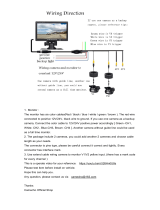
This document describes the steps necessary to deploy an installation of the JAI Vehicle Imaging
Subsystem, described as VIS from this point forward. The core of this subsystem is a traffic optimized
series of camera systems. This manual will discuss specifically the VISCAM 1000 system. The system
combines an industry leading vehicle imaging camera with high performance triggering/light sensing and
LED illumination, all in a sleek, weatherproof housing.
This manual also contains information about maintenance and troubleshooting.
JAI strongly recommends that the installer reads this manual thoroughly, in order to obtain sufficient
knowledge about the VIS equipment, before initiating the actual installation.
1.2 Product Overview and System Hardware Components
Figure 1. VISCAM 1000 Installation Overview

VISCAM 1000 Systems
2 Introduction
1.2.1 VISCAM 1000 System
The VISCAM 1000 uses a state-of-the-art camera system that freezes the motion of a rapidly moving vehicle
at high resolution, a zoom-lens or fixed focal length lens, and an on-axis illuminator, a weatherproof
housing with sun shield, heater resistors, I/O board, and a pan-tilt-roll mounting bracket. See Figure 2.
The VISCAM 1000 (All-In-One) features an optional embedded JAI trigger/light sensor for image triggering
and image contrast control. It also features an optional embedded LED-1000 illuminator (infrared, white or
blue) for independent 24/7 operation and excellent license plate contrast.
1.2.2 External Traffic Light Sensor – TLS-301 (optional)
The JAI Traffic Light Sensor TLS-301 provides an option to using VISCAM 1000’s built-in light sensing
capabilities described in Section 4.10.3. The TLS-301 estimates vehicles’ license plate lighting conditions
and controls the exposure and gain parameters of each camera to ensure high contrast images of vehicles
traveling through the field of view and their license plates, regardless of vehicle speed, weather or
ambient light conditions. For more information about the TLS-301, see Appendix B at the end of this
document.
1.2.3 External Light Sources
JAI offers a full lineup of lighting solutions optimized for a large number of applications.
The TNF-35 Traffic Night Flash unit is a 17W, long-life flash with an effective life span of up to 4 million
flashes. It comes in various application specific configurations for emission spectrum. With the standard
filter it generates light in wavelengths that are invisible to the human eye, but visible to the camera. For
more information about the TNF-35, see Appendix C at the end of this document.
The TNL-50 is a newer, high-performance LED Flash intended for traffic applications, including automated
number plate reading systems. The TNL-50 is field proven to produce high-contrast images of passing
vehicles and their number plates. With its very high light output, versatility, ease of installation and its
compact size, it makes it easy to see why it is an industry leading illumination solution. It also comes in
three configurations, broadband white, NIR, and blue to support various applications. Additional
information about installing and configuring the TNL-50 can be found in Sections 3.3 and 4.7 of this
document.
Both the TNL-50 and TNF-35 are automatically enabled whenever the camera or the optional TLS-301 Light
Sensor determines that ambient light is insufficient to produce a picture of usable quality.
1.2.4 Embedded Light Sources (LED-1000 IR, white or blue)
Various applications require the use of an embedded illuminator. JAI offers the LED-1000 illuminator with
infrared, white, or blue LEDs. See Figure 2.
1.2.5 VJP-300 Junction Panel
The J-Panel is the central connection point for the VIS components. The J-Panel is a DIN-Rail mounted PCB
(printed circuit board) equipped with various interface terminals for interconnection. Each J-panel can
support up to two VISCAM systems.
1.2.6 Optional 24V DC Power Supply
JAI provides a robust industrial rated power supply.
1.2.7 Optional gigabit Ethernet switch
JAI recommends using a field-proven industrial rated gigabit Ethernet switch.
1.2.8 System interconnection cables
JAI supplies a cabling solution that has proven its reliability on a large number of installation sites.

Introduction 3
VISCAM 1000 Systems
1.3 VISCAM 1000 Product Line
The VISCAM 1000 houses a JAI TS(C)-5000EN camera. The EN camera series are Ethernet based with a built
in processor using an embedded Linux O/S for various operations, such as handling communication with
lane controller and back office, frame storage, JPEG compression, and so on. An optional external TLS-301
Traffic Light Sensor is available, as well as optional embedded LED-1000 illuminator.
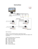
Figure 2. VIS-CAM 1000 System With EIO 302 I/O board and LED-1000

VISCAM 1000 Systems
4 Installing the VIS
2 Preparing for installation
2.1 Installation Preparation
To prepare for installation, consider the fundamental requirements for an effective deployment of the
Vehicle Imaging Subsystem. There are two basic configurations: overhead (over the lane) or side fire
(beside the lane). Figure 3 depicts a typical overhead configuration. Figure 4 depicts a typical side fire
configuration.
2.2 Overhead Positioning
Over lane camera mounting is always employed when the road width being monitored contains three or
more lanes of traffic, when a convenient overhead structure is already in place, or when preventing
vandalism is a paramount concern.
Figure 3. Typical Overhead Site Layout for a single lane

Installing the VIS 5
VISCAM 1000 Systems
(a) Single Lane or Dual lane considerations
Figure 3 shows a typical single lane configuration. However, with the VISCAM 1000’s higher 5Mpixel
resolution, it can now cover up to two lanes of traffic.
The VISCAM 1000’s varifocal (zoom) lens is adjusted during installation to create the following conditions:
Standard for US style of plates: 135 pixels across a 1 foot wide license plate placed 2 feet above the ground
level at the nominal trigger position (ground loop, etc.). With typical US lane coverage (14’), the VISCAM
1000 will yield ~180 pixels/plate. If maintaining the 135 pixels per plate, the lane coverage is now 18’.
Standard for European style of plates: 140 pixels across a 50 cm wide license plate placed 60 cm above the
ground level at the nominal trigger position (ground loop, etc.). The coverage is now up to 9 meters, which
can definitely cover two lanes.
(Note: this can differ for other regions or plate styles.) See Section 4 for set up instructions. This resolution
maximizes license plate reader, vehicle matcher, or other image processing techniques performance. The
highest performance from the subsystem is achieved when the variation in plate size is kept to within ±5%,
which typically means that the vehicle trigger accuracy should be within ±1 foot/30 cm (@ trigger plane
defined by client.) at all speeds. Low latency vehicle triggering is very important and should not be
overlooked. Please contact JAI for support on this issue if needed.
(b) Camera tilt considerations
The requirement to freeze the motion of high-speed vehicles limits how steep or shallow the tilt angle of
the camera may be. For example, it is important to prevent the horizon from appearing in the image, and
thereby allowing the sun to blind the camera. For over lane installations, a camera tilt between 20° to 30°
is recommended, with 25° being considered the optimal angle. This angle of tilt is the best compromise
between minimizing visibility blockages caused by closely spaced vehicles and maximizing plate visibility
for plate mounts that are slightly recessed or tilted downwards.
(b) Asynchronous triggering considerations
An embedded vehicle detector is employed to cause the camera to capture an image at the precise
moment the vehicle is in the best position to image both the vehicle and its license plate. If an external
triggering device is used (i.e. ground loop) the delay between the time the vehicle passes the trigger
position on the road and when the trigger signal actually reaches the VISCAM 1000 must be kept to a
minimum to prevent high-speed vehicles from moving out of the area viewed by the camera before the
image is snapped.
(c) Camera height versus trigger distance considerations
It is critically important to select the correct distance between the camera and the location on the road
where the camera is triggered to capture an image. Minimizing the cost of installation is usually also an
important concern. This means that whenever possible, it is best to use existing structures or previously
installed elements. Contact JAI for support on setting/validating site geometry.

VISCAM 1000 Systems
6 Installing the VIS
2.3 Side of Road Installation
Figure 4. Typical side fire road installation for a single lane
Table 1 below shows the typical distance from VISCAM 1000 to flash/light unit (distance normal from
camera-license plate axis):
Table 1 Typical spacing distance between VISCAM 1000 and flash/light unit
VISCAM 1000
Approx. Distance
in Feet
3.5
Approx. Distance
in Meters
1.0
If the flash is positioned closer to the camera, reflections from retro-reflective license plates will likely
cause overexposure. If it is positioned farther the license plates will be relatively less bright and the image
quality might be deteriorated since more gain will have to be applied by the camera in order to make the
license plates bright enough for ALPR. A solution to this would be to increase the light intensity of the flash
unit.
If the distance from the camera to the trigger line is further than 50 ft then the spacing between flash and
camera will have to be increased to avoid increasing the retro-reflectivity effect, and the flash light
intensity will have to be increased or else the background will not be visible in the image even when retro-
reflective license plates are close to saturation.

Installing the VIS 7
VISCAM 1000 Systems
3 Installing the VIS - Vehicle Imaging System
The individual components of the system are electrically linked together as shown in Figure 1, “VISCAM
1000 Installation Overview”.
3.1 VIS Power Requirements
The maximum power to a VJP-300 J-Panel is:
SYSTEM COMPONENTS
CURRENT
(STEADY STATE)
CURRENT
(INRUSH)
VISCAM 1000 System #0 (with heater on)
2.0A
3.5A
VISCAM 1000 System #1 (with heater on)
2.0A
3.5A
VJP-300 J-Panel
0.2A
1.5A
Total
4.2A
6.5A*
* Since all devices are connected to VJP-300 J-Panel, it limits total inrush current to 6.5A.
3.1.1 Installing the VISCAM 1000 System
The VISCAM 1000 has connections to the J-Panel and an optional Flash Night Light. In general, the
camera(s) should be aimed at the most likely cross-lane position of the vehicle license plates. See
“Installation Preparation” in Section 2 for general site layout guidelines. To install the camera(s):
1. Attach VISCAM 1000, with mount, to the mounting structure. The hole pattern is shown in Figure 5 below:
Figure 5. VISCAM 1000 Mount Dimensions.

VISCAM 1000 Systems
8 Installing the VIS
2. Route the VISCAM 1000 end of the camera cable in accordance with local electrical code requirements.
3. The jacket is removed from the cable on the camera end a distance of 7” (~18cm) (1). A thin wire is attached
around the end of the cable to keep the braid in place (2). The cord grip sealing nut is mounted on the cable
(3). See Figure 6.
Figure 6. VISCAM 1000 cabling as it appears after jacket is removed
4. Route cable through enclosure cord grip. Braid/foil shield should be aligned with the cord grip nut inside
enclosure to ensure proper shield connection with EMI cord grip. See Figure 7.
Figure 7. Cable is routed properly to ensure proper shield connection
5. Hand-tighten the sealing nut as far as possible. Hold the body hex stationary with a wrench (24mm). Using a second
wrench (24mm), tighten the sealing nut until the cable is securely held in place. Torque to approximately 35 in. lbs.
(3.9 Nm)
6. Move the thin wire 5 cm away from the cable end and fold the braid back over the thin wire. Use a cable strip to keep
the braid in place. Remove foils and fillers from the cable end. Separate and strip the wires. The 2 pairs of multicore
wire can be fitted with bootlace ferrules to keep the cores in place. Connect wires to terminal block X4 on the VISCAM
1000 I/O Board in accordance with wiring diagram on enclosures inner lid (see Appendix A). Plug terminal block back to
X4 position on VISCAM 1000 I/O Board. Close and secure enclosure lid with 2 latches. See Figures 8 and 9.
Figure 8. VISCAM 1000 Cabling.
3
1
2
Outer
Braid
Grounding
Tongues
Grounding
Tongues
Braid is
folded back

Installing the VIS 9
VISCAM 1000 Systems
Figure 9. Wires are inserted in VISCAM 1000 I/O board X4 connector
3.2 Installing the VJP-300 Junction Panel
3.2.1 Connection to VISCAM 1000 (X1 AND X2)
The VISCAM 1000 connections to the J-Panel (junction panel) are shown in Table 2 and Figure 10.
Table 2 VISCAM 1000 connections to the J-Panel.
VJP-300
X1, X2 Pin #
VISCAM AIO
X4 Pin #
Wire Color
Signal
Remarks
1
1
White/orange in Cat5e cable
Ethernet A+
2
2
Orange in Cat5e cable
Ethernet A-
3
3
White/green in Cat5e cable
Ethernet B+
4
4
Green in Cat5e cable
Ethernet B-
5
5
White/blue in Cat5e cable
Ethernet C+
6
6
Blue in Cat5e cable
Ethernet C-
7
7
White/brown in Cat5e cable
Ethernet D+
8
8
Brown in Cat5e cable
Ethernet D-
9
9
Black wire
Gnd
18 AWG
10
10
Red wire
+24V dc
18 AWG
11
11
Grey
Vinit+
Trigger signal, 24 AWG
12
12
Yellow
Vinit-
Trigger signal, 24 AWG
13
nc
14
nc
15
nc
16
nc

VISCAM 1000 Systems
10 Installing the VIS
Figure 10. VJP-300 J-Panel X1 and X2 connectors
The connectors on the VJP-300 J-Panel are pluggable terminal blocks with pin spacing of 3.81 mm/ 0.15
inch from WAGO. The contacts are spring loaded. See Figure 11.
Figure 11. Terminal block
When mounting the wire into the connector the wire is stripped 7mm. The connector spring is released by
using one of two tools:
WAGO 734-230
JAI part number 10010134
WAGO 210-250
JAI part number 10014057
The wire is inserted and the spring is activated.

Installing the VIS 11
VISCAM 1000 Systems
3.2.2 X6 Power Input Connector
The Power Input connection to the J-Panel is shown in Table 3 and Figure 12. Note: X7 is in parallel to X6.
Table 3 Power input to the J-Panel
X6 Pin #
Signal
Description
Connection to
1
+24V
+24V dc
24V DC power supply + output
2
GND
+24V return
24V DC power supply return
Figure 12. X-6 Power input connection
3.2.3 Trigger Input Connector (X14)
The Trigger input connection to the J-Panel is connector X14. The connections are listed in Table 4 and
Figure 13.
Table 4 Trigger input connector.
X14 Pin #
Signal
Description
Connection to
1
Trig0+
Positive Trigger input to camera 0
Trigger device positive terminal
2
Trig0-
Negative Trigger input to camera 0
Trigger device negative terminal
3
Trig1+
Positive Trigger input to camera 1
Trigger device positive terminal
4
Trig1-
Negative Trigger input to camera 1
Trigger device negative terminal
3.2.5 (a) Trigger polarity
The switches S3 and S5 set the trigger polarity.
If the trigger signal is normally low (no voltage at trigger input) the switch shall be in position:
Arrow up - positive going
If the trigger signal is normally high (voltage at trigger input) the switch shall be in position:
Arrow down – negative going

VISCAM 1000 Systems
12 Installing the VIS
As a guideline the two LEDs marked TRIG-0 and TRIG-1 on the VJP-300 J-Panel shall be off when no trigger
pulse is present.
3.2.5 (b) Test Trigger
Activating switches (push buttons) S1 and S4 generates a trigger pulse for test purposes. Only one trigger
pulse is generated each time the switch is activated (only works in arrow up position).
The duration of the trigger pulse is approximately 4 ms.
The trigger indicator LEDs flash when the test trigger switch is activated.
Figure 13. X14 Wiring
3.3 Installing the TNL-50
Securely install night light/flash unit on mounting structure. Roughly aim flash at trigger line (precision
aiming will occur when the system is up and running). See night light datasheet for mounting hole pattern
dimensions.
1. Disconnect wires from interconnection cable’s end connector in order to run cable through VISCAM
1000 enclosure’s cordgrip.
2. Route cable through enclosure cord grip. Braid/foil shield should be aligned with the cord grip nut
inside enclosure to ensure proper shield connection with EMI cord grip. See Figure 14 (left).
3. Hand-tighten the cord grip sealing nut as far as possible. Hold the body hex stationary with a wrench.
Using a second wrench, tighten the sealing nut until the cable is securely held in place. Torque to
approximately 35 in-lbs. (3.9 Nm). See Figure 14 (right).
Figure 14. Insert cable in enclosure and secure cordgrip
4. Connect wires to terminal blocks X5 & X12 on the VISCAM 1000 I/O Board in accordance with wiring diagram
on enclosure’s inner lid (see appendix A). Make sure settings are set per I/O Board Settings Diagram:
a. For TNL-50 Refer to Figure 15 and Table 5.

Installing the VIS 13
VISCAM 1000 Systems
Figure 15. Connect TNL-50 wires to terminal blocks X5 and X12 on I/O Board
Table 5 TNL-50 flash unit connection in VISCAM AIO.
Pin X5
Signal
Wire Color
Description
Connection to
1
I/O Gnd
Black
I/O Board Gnd
Pin 2 (see Figure 15)
2
Gnd
Black
Flash Gnd
Flash ground (negative power terminal)
(GROUND)
3
Out
White
Strobe out
Strobe input on flash unit (STROBE OUT)
4
Stat
Blue
Strobe status
Status output from flash unit (STROBE
STATUS)
5
FPWR
Red
Flash power
Power from I/O Board to output circuit on
I/O Board (pin 6)
6
24V
Red
IO board 24V (Fused
0.5A)
Pin 5 (see Figure 15)
Pin X12
Signal
Wire Color
Description
Connection to
7
RS-485+
Green
RS-485+
For controlling TNL-50 Parameters
8
RS-485-
Orange
RS-485-
For controlling TNL-50 Parameters

VISCAM 1000 Systems
14 System Set-Up
4 System Set-Up
This section provides a generic procedure for aligning one or more VISCAM 1000 system and associated
equipment at a site.
The example installation process described in this section assumes that:
The cameras are being mounted on an overhead structure directly over the lane(s) being observed. The process
for aligning a camera mounted at the side of a lane is essentially the same as aligning a single camera mounted
directly overhead.
The unit employs vehicle detection that will automatically trigger the camera. To determine where the vehicle
will trigger, the ENSetup program displays a trigger area region. This region shows the area where the camera
will detect a moving vehicle. This will give the approximate trigger line. Since the unit is using motion
detection technology, the trigger line will vary a little depending on the speed of the vehicle.
If the installation utilizes other modes for triggering, the unit can also accept a discrete TTL or Ethernet signal
to the VISCAM 1000 system whenever the back (or front) of a vehicle crosses a fixed line across the road. This
line is referred to as the “trigger line” in this document.
The installer should be familiar with using the ENSetup program supplied by JAI. Make sure you are using the
latest version by checking at www.jai.com. Please refer to the ENSetup Program User’s Guide if you are
unfamiliar with this software. JAI offers engineering support and software tools to help select the optimum
camera and trigger locations to meet your specific project needs.
System settings are set to factory default value. This can be done by pressing the Load Factory Defaults button
on the tool bar in the Properties window.
4.1 Pre-Alignment Checklist
Validate targeted lane coverage and lane overlap (if any)
Make sure you have an appropriate laptop computer with the JAI ENSetup program installed.
The setup computer needs to have an Ethernet network adapter installed (preferably 1 Gigabit Ethernet
Adapter) and the TCP/IP network configured with the correct IP-address, subnet-mask and default-gateway.
The setup computer and the cameras need to be on the same subnet. The cameras are shipped with the
standard IP-address “10.0.0.65” and subnet-address “255.255.255.0”, and the setup computer needs to be
assigned an IP-address “10.0.0.xx” in order to automatically discover the cameras using the ENSetup program
(NB! “xx” must not be “65”).
All cameras have to be given unique IP-addresses before the alignment begins. This is done using the ENSetup
application.
Confirm all VIS components and cables are properly connected.
Ensure network meets minimal system requirements (see Appendix D)
4.2 Select a Suitable Vehicle, License Plate, and Plate Stand for the Setup
To accurately set up the Vehicle Imaging Subsystem, the system installers need access to:
1. A vehicle that can be temporarily parked on the road
2. A plate that is:
a. typical in size and color for the site
b. clean, flat and in “like new” condition
/