Page is loading ...

Installation Manual & Quick Start Guide
Document P/N: 10895
Document Version: B
© 2015 JAI
Drive5
HIGH PERFORMANCE CAMERA SYSTEM
FOR ANPR APPLICATIONS

― 2 ―
Notice
The material contained in this manual consists of information that is proprietary to JAI Inc., and may
only be used by the purchasers of the product. JAI Inc. makes no warranty for the use of its product
and assumes no responsibility for any errors which may appear or for damages resulting from the use
of the information contained herein. JAI Inc. reserves the right to make changes without notice.
Microsoft Windows 8, Windows 7, Windows XP, Windows 2000, Windows 98, Windows NT, and
Windows Explorer are either registered trademarks or trademarks of Microsoft Corporation in the
United States and/or other countries.
Warranty
Each JAI product is warranted to be free from defects in material and workmanship under normal
intended use and service if installed in accordance with this manual. The standard warranty period for
the Drive5 is 1 year (12 months) and begins on the date of shipment from JAI stock.
This warranty shall not apply to repairs or replacements necessitated by any cause beyond the
control of JAI, including but not limited to, 1) improper installation, 2) acts of nature, 3) accidents, 4)
misuse, 5) lack of proper maintenance, 6) unauthorized repairs or modifications.
Be advised, that you need to obtain an RMA number from JAI before returning units for warranty
repair.

― 3 ―
Certifications
CE Compliance
The Drive5 has been certified to conform to the requirements of Council Directive 89/336/EC for
electromagnetic compatibility and to comply with the following European Standards:
Emissions: EN 55022A: 2010/AC:2011
Immunity: EN 61000-4
All JAI products bearing the CE mark have been declared to be in conformance with the applicable
EEC Council Directives. However, certain factory-installed options or customer-requested
modifications may compromise electromagnetic compatibility and affect CE compliance. Please note
that the use of interconnect cables that are not properly grounded and shielded may affect CE
compliance.
Contact JAI Applications Engineering Department for further information regarding CE compliance.
FCC
This equipment has been tested and found to comply with the limits for a Class A digital device,
pursuant to Part 15 of the FCC Rules. These limits are designed to provide reasonable protection
against harmful interference when the equipment is operated in a commercial environment. This
equipment generates, uses, and can radiate radio frequency energy and, if not installed and used in
accordance with the instruction manual, may cause harmful interference to radio communications.
Operation of this equipment in a residential area may cause harmful interference, in which case the
user will be required to correct the interference at his own expense.
IP66
This equipment has been tested and found to comply with IP66. This proves that the equipment is
resistant to rain and dust in severe outdoor environments.
Warning:
Changes or modifications to this unit not expressly approved by the party responsible for FCC
compliance could void the user’s authority to operate the equipment.
September 28, 2015

― 4 ―
Table of Contents
Table of Contents ............................................................................................................................................. 4
Quick Start Guide ............................................................................................................................................. 5
Drive5 System Installation Manual ................................................................................................................... 8
1 Introduction ........................................................................................................................................... 8
1.1 Document overview ...................................................................................................................... 8
1.2 Product overview and system hardware components .................................................................. 8
2 Preparing for installation ..................................................................................................................... 10
2.3 Installation preparation ............................................................................................................... 10
2.4 Overhead positioning .................................................................................................................. 10
2.5 Side of road installation .............................................................................................................. 12
2.6 Flash considerations ................................................................................................................... 12
3 Installing the Drive5 system ................................................................................................................ 14
3.1 Drive5 power requirements ......................................................................................................... 14
3.2 Installing the Drive5 system ........................................................................................................ 14
4 System setup ...................................................................................................................................... 17
4.1 Pre-alignment checklist ............................................................................................................... 18
4.2 Select a suitable vehicle, license plate, and plate stand for the setup ....................................... 19
4.3 Connect the setup computer to the camera ............................................................................... 19
4.4 Drive and park the setup vehicle correctly .................................................................................. 20
4.5 Perform initial lens adjustment and camera aiming .................................................................... 20
4.6 LED Ring Light embedded illuminator setup .............................................................................. 20
4.7 Automatic triggering and light sensing configuration .................................................................. 23
4.8 High dynamic range (HDR) settings ........................................................................................... 27
4.9 Time synchronization settings .................................................................................................... 29
4.10 Video streaming .......................................................................................................................... 30
5 Appendix A: Drive5 I/O Board Connection Overview ......................................................................... 33
5.1 Power requirements – Drive5 system ......................................................................................... 34
6 Appendix B: Troubleshooting and maintenance ................................................................................. 35
7 Appendix C – List of acronyms used .................................................................................................. 38

― 5 ―
Quick Start Guide
1. Remove the camera from the box. Mount it securely.
a. Loosen the pan, tilt, roll adjustments enough to move but snug enough to hold position
2. Electrical setup (assumes JAI cable is used)
a. Connect the system cable to the I/O Board according to the table below
Drive5 X4 connector
pin number
Wire color
Signal
1
White/orange in Cat5e cable
Ethernet A+
2
Orange in Cat5e cable
Ethernet A-
3
White/green in Cat5e cable
Ethernet B+
4
Green in Cat5e cable
Ethernet B-
5
White/blue in Cat5e cable
Ethernet C+
6
Blue in Cat5e cable
Ethernet C-
7
White/brown in Cat5e cable
Ethernet D+
8
Brown in Cat5e cable
Ethernet D-
9
Black wire
GND
10
Red wire
+24V dc
11
Grey
Vinit+
12
Yellow
Vinit-
Figure 1. System cable connected to I/O Board

― 6 ―
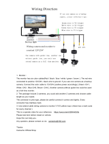
b. Connect the other end of the cable to power (Black/Red) (24VDC)
c. Remove the internal cable from the camera’s RJ45 connector and connect the laptop
Ethernet adapter directly to the camera’s RJ45 connector.
Figure 2. Connect laptop to camera’s RJ45 connector
d. Apply power (24V DC). The I/O Board has 4 LEDs to indicate status. See Appendix A for the
locations of these LEDs and see Appendix B for troubleshooting information.
e. Configure your network adapter for a static IP of 10.0.0.xx, with xx being anything but 65.
This will put the computer on the same subnet as the camera (as configured at the factory,
the camera is set to 10.0.0.65). See Figure 16 for an example.
f. Start EN Setup on laptop. Wait approximately 1 minute for the camera to boot up.
g. Click on the Video button, then on the camera in the left pane.
Figure 3. EN Setup Video Window
h. Click on the “Live” button to start image acquisition.
Disconnect internal Drive5
cable and connect laptop
to here as shown
Click on camera
“Live” button

― 7 ―
i. Using the pan, tilt and roll adjustments on the mount, aim the housing at the target.
j. Loosen the lens adjustment thumbscrews.
k. Adjust the focus, and if necessary the zoom adjustments on the lens to achieve the field of
view you desire. Right click on the image and select “Preview Image” to get a view of the
entire image.
l. Readjust the pan, tilt, roll, zoom and focus until satisfied with the field of view and focus.
Figure 4. Properly adjusted image (dual-lane setup)
m. Tighten lens adjustment thumbscrews.
n. Lock down the pan, tilt and roll adjustments.
o. Remove Ethernet cable from the camera RJ45 and reinstall the cable from the I/O Board
RJ45 into the camera RJ45.
p. Close and latch the lid.

― 8 ―
Drive5 System Installation Manual
1 Introduction
1.1 Document overview
This Installation Manual details steps for deployment of the Drive5 traffic camera system, as well as
maintenance and troubleshooting information. The system consists of a high performance camera,
LED illumination, weatherproof long-lasting housing, and I/O Board
JAI strongly recommends that the installer reads this manual thoroughly, in order to obtain sufficient
knowledge about the Drive5 equipment, before initiating the actual installation.
1.2 Product overview and system hardware components
Figure 5. Drive5 components overview (not to scale)
The Drive5 uses a state-of-the-art 5.3-megapixel camera system with a 1-inch format CMOS image
sensor that freezes the motion of a rapidly moving vehicle at high resolution. The system includes a
fixed focal length lens; an on-axis illuminator; and a weatherproof housing with sun shield, heater
resistors, I/O Board, and a pan-tilt-roll mounting bracket.
The Drive5 features an embedded JAI trigger/light sensor for image triggering and image contrast
control. It also features an embedded LED Ring Light illuminator (infrared, white or blue) for
independent 24/7 operation and excellent license plate contrast (see Figure 6).
The Drive5 system is Ethernet based with a built-in processor using an embedded Linux O/S for
various operations, such as data transfer to the back office, frame storage, JPEG compression, and
so on.
Installing the Drive5 involves connecting a system cable (sold separately) to the I/O Board in the
Drive5 system (see Quick Start Guide or Section 3 for instructions). The other end of the system
cable connects to your power source, your network, and your Vinit trigger input. JAI provides, and
strongly recommends, the use of a J-panel board (sold separately) to make these connections. The J-
Panel is a DIN-rail-mounted PCB (printed circuit board) equipped with various interface terminals for
interconnection. Each J-panel can support up to two Drive5 systems.
Drive5 System
System Cable
(sold separately)
J-Panel
(sold separately)

― 9 ―
Figure 6. Drive5 system with I/O Board and LED Ring Light
I/O Board
LED Ring Light

― 10 ―
2 Preparing for installation
2.3 Installation preparation
To prepare for installation, consider the fundamental requirements for an effective deployment of the
Vehicle Imaging Subsystem. There are two basic configurations: overhead (over the lane) or side fire
(beside the lane). Figure 7 depicts a typical overhead configuration. Figure 9 depicts a typical side fire
configuration.
2.4 Overhead positioning
Over lane camera mounting is always employed when the road width being monitored contains three
or more lanes of traffic, when a convenient overhead structure is already in place, or when preventing
vandalism is a paramount concern. Each Drive5 system can be configured to cover a single lane or
two lanes, depending on type of plate and standard lane sizes.
Figure 7. Typical overhead site layout – one Drive5 per lane (with optional external flash units)

― 11 ―
Single lane or dual lane considerations
Figure 7 shows a typical single lane configuration. However, with the Drive5’s higher 5-megapixel
resolution and 1-inch sensor format, it can cover up to two lanes of traffic. The Drive5’s lens is
adjusted during installation to create the following conditions:
Standard for US style of plates: 135 pixels across a 1 foot wide license plate placed 2 feet above the
ground level at the nominal trigger position (ground loop, laser, etc.). With typical US lane coverage
(14’), the Drive5 will yield ~180 pixels/plate. If maintaining 135 pixels per plate, the lane coverage is
now 18’.
Standard for European style of plates: 140 pixels across a 50 cm wide license plate placed 60 cm
above the ground level at the nominal trigger position (ground loop, etc.). The coverage is now up to
9 meters, which can definitely cover two lanes (see Figure 8 below).
Figure 8. Typical overhead site layout – dual-lane coverage (with optional external flash unit)
Camera tilt considerations
The requirement to freeze the motion of high-speed vehicles limits how steep or shallow the tilt angle
of the camera may be. For example, it is important to prevent the horizon from appearing in the
image, and thereby allowing the sun to blind the camera. For over lane installations, a camera tilt
between 20° to 30° is recommended, with 25° being considered the optimal angle. This angle of tilt is
the best compromise between minimizing visibility blockages caused by closely spaced vehicles and
maximizing plate visibility for plate mounts that are slightly recessed or tilted downwards.
Asynchronous triggering considerations
An embedded vehicle detector is employed to cause the camera to capture an image at the precise
moment the vehicle is in the best position to image both the vehicle and its license plate. If an
external triggering device is used (i.e., ground loop or laser) the delay between the time the vehicle
passes the trigger position on the road and when the trigger signal actually reaches the Drive5 must
be kept to a minimum to prevent high-speed vehicles from moving out of the area viewed by the
camera before the image is snapped.

― 12 ―
2.5 Side of road installation
Figure 9. Typical side-fire road installation – one lane per Drive5 system (with optional external flash)
2.6 Flash considerations
The Drive5 system comes equipped with a built-in on-axis LED illuminator (LED Ring Light) designed
to capture nighttime images of retro-reflective number plates, or to enhance the brightness of daytime
plate images in shade conditions or under cloudy or foggy skies.
For illumination of both plates and vehicles under nighttime conditions, the Drive5 system can be
integrated with the optional TNL-50 external flash unit. By positioning this high-powered flash unit a
short distance away from the Drive5, proper exposure of the overall scene can be achieved without
overexposing the plate. Table 1 below shows the minimum distance from Drive5 to flash/light unit
(distance normal from camera-license plate axis):
Drive 5
Unit to Flash Spacing (minimum)
Approximate distance in feet
3.25
Approximate distance in meters
1.0
Table 1 Minimum spacing distance between Drive5 and flash/light unit
If the flash is positioned closer to the camera, reflections from retro-reflective license plates will likely
cause overexposure. Tests have shown that positioning the flash up to two meters (6.5 feet) away
from the Drive5 will generally produce good results.

― 13 ―
If the distance from the camera to the trigger line is further than 50 feet, then the spacing between
flash and camera will have to be increased to avoid increasing the retro-reflectivity effect, and the
intensity of the flash will have to be increased or else the background will not be visible in the image
even when retro-reflective license plates are close to saturation.

― 14 ―
3 Installing the Drive5 system
The individual components of the system are electrically linked together as shown in Appendix A,
“Drive5 I/O Board Connection Overview.”
3.1 Drive5 power requirements
The Drive5 system requires a 24V DC power supply. The table below shows the power consumption
for two Drive5 units connected to a power supply via the recommended J-Panel board (4.2 * 24 =
100.8 W, steady state). For direct connection of a single unit to a 24V DC power supply, inrush
current is 3.5 A, steady state current is 2.0 A.
System Components
Current (Steady State)
Current (Inrush)
Drive5 System #0 (with heater on)
2.0 A
3.5 A
Drive5 System #1 (with heater on)
2.0 A
3.5 A
J-Panel (VJP-300)
0.2 A
1.5 A
Total
4.2 A
6.5 A*
* When connected using J-Panel, inrush current is limited to 6.5 A
Table 2 Drive5 power requirements
3.2 Installing the Drive5 system
Step 1: Attach Drive5, with mount, to the mounting structure. The hole pattern is shown in Figure 10.
Figure 10. Drive5 mount dimensions
Figure 11. Drive5 pan-tilt-roll base
Mounting holes

― 15 ―
Step 2: Route the Drive5 end of the system cable in accordance with local electrical code
requirements.
Step 3: The jacket is removed from the cable on the camera end a distance of 7” (~18cm) (1). A thin
wire is attached around the end of the cable to keep the braid in place (2). The cord grip sealing nut is
mounted on the cable (3). See Figure 12.
Figure 12. Drive5 system cabling as it appears after jacket is removed
Step 4: Route cable through enclosure cord grip. Braid/foil shield should be aligned with the cord grip
nut inside enclosure to ensure proper shield connection with EMI cord grip. See Figure 13.
Figure 13. Cable is routed properly to ensure proper shield connection
Step 5: Hand-tighten the sealing nut as far as possible. Hold the body hex stationary with a 24 mm
wrench. Using a second 24 mm wrench, tighten the sealing nut until the cable is securely held in
place. Torque to approximately 35 in. lbs. (3.9 Nm) Note: there is no standard SAE wrench size that
will properly fit the hex nuts. You must use either a 24 mm metric wrench or an adjustable wrench.
Step 6: Move the thin wire 2 inches (5 cm) away from the cable end and fold the braid back over the
thin wire. Use a cable strip to keep the braid in place. Remove foils and fillers from the cable end.
Separate and strip the wires. The 2 pairs of multicore wire can be fitted with bootlace ferrules to keep
the cores in place. Connect wires to terminal block X4 on the Drive5 I/O Board in accordance with
wiring diagram on enclosures inner lid (see Appendix A and Figures 14 and 15 on the following
page). Plug terminal block back to X4 position on Drive5 I/O Board. Close and secure enclosure lid
with 2 latches.
(3)
(1)
(2)
Outer
braid
Grounding
tongues

― 16 ―
Figure 14. Drive5 system cable
Figure 15. Wires are inserted in Drive5 I/O Board X4 connector

― 17 ―
4 System setup
This section provides a generic procedure for aligning one or more Drive5 system and associated
equipment at a site.
The example installation process described in this section assumes that:
The cameras are being mounted on an overhead structure directly over the lane(s) being
observed. The process for aligning a camera mounted at the side of a lane is essentially the
same as aligning a single camera mounted directly overhead.
The unit employs vehicle detection that will automatically trigger the camera (see Section
4.7). To determine where the vehicle will trigger, the EN Setup program can be made to
display a trigger area region. This function is enabled by clicking on Debug Output Mask in
Section 1 of the EN Setup camera properties and selecting ”On Image Graphics” as shown
below.
This region shows the area where the camera will detect a moving vehicle. This will give the
approximate trigger line. Since the unit is using motion detection technology, the trigger line
will vary a little depending on the speed of the vehicle.
If the installation utilizes other modes for triggering, the unit can also accept a discrete TTL or
Ethernet signal to the Drive5 system whenever the back (or front) of a vehicle crosses a fixed
line across the road. This line is referred to as the “trigger line” in this document.
The installer should be familiar with using the EN Setup program supplied by JAI. Make sure
you are using the latest version by checking at www.jai.com. Please refer to the EN Setup
Program User’s Guide if you are unfamiliar with this software. JAI offers engineering support

― 18 ―
and software tools to help select the optimum camera and trigger locations to meet your
specific project needs.
System settings are set to factory default value. This can be done by pressing the Load
Factory Defaults button on the tool bar in the Properties window.
4.1 Pre-alignment checklist
Validate targeted lane coverage and lane overlap (if any)
Make sure you have an appropriate laptop computer with the JAI EN Setup program
installed.
The setup computer needs to have an Ethernet network adapter installed (preferably 1
Gigabit Ethernet Adapter) and the TCP/IP network configured with the correct IP-address,
subnet-mask and default-gateway.
The setup computer and the cameras need to be on the same subnet. The cameras are
shipped with the standard IP-address “10.0.0.65” and subnet-address “255.255.255.0”, and
the setup computer needs to be assigned an IP-address “10.0.0.xx” in order to automatically
discover the cameras using the EN Setup program (NB! “xx” must not be “65”).
Figure 16. Assigning IP addresses
All cameras have to be given unique IP-addresses before the alignment begins. This is done
using the EN Setup application.

― 19 ―
Confirm all Drive5 components and cables are properly connected.
Ensure network meets minimal system requirements.
4.2 Select a suitable vehicle, license plate, and plate stand for the setup
To accurately set up the Vehicle Imaging Subsystem, the system installers need access to:
1. A vehicle that can be temporarily parked on the road
2. A plate that is:
Typical in size and color for the site
Clean, flat and in “like new” condition
4.3 Connect the setup computer to the camera
Position the setup computer next to the camera being aligned. Make sure that nothing interferes with
the camera’s view of the road.
Connect the setup computer’s network adapter directly to the camera. Configure your network
adapter for a static IP of 10.0.0.xx, with xx being anything but 65. This will put the computer on the
same subnet as the camera (as configured at the factory, the camera is set to 10.0.0.65).
Figure 17. Example of direct connection to the camera
Once the setup computer is connected, you can apply power to the Drive5 (24V DC). The I/O Board
has 4 LEDs to indicate the status of the heaters, power supply, and microcontroller (I/O Board setup
parameters). Appendix A shows the locations of these LEDs. Appendix B contains an explanation of
the meaning of the lights and the colors that indicate proper operation.
Disconnect internal camera
cable from here and plug in
patch cable from setup
computer.

― 20 ―
4.4 Drive and park the setup vehicle correctly
Park the vehicle on the trigger line. Make sure that the vehicle is parked aimed in the same direction
as the average driver would point their car if they were driving through this section of roadway.
4.5 Perform initial lens adjustment and camera aiming
1. Loosen the roll, pan, and tilt bolts on the JAI camera mounting head until each axis can be easily
adjusted by hand but any particular setting will stay in place after you let go. (Slight amount of
friction)
2. Power on the setup computer and then start the EN Setup program. Wait approximately 1 minute
for the camera to boot up.
3. Press the “Video Window” button to open the Video Window and then select the camera for
adjustment from the tree-view on the left side of the window. Press the “Live” button in the toolbar
to start rapid image acquisition. “Live” mode disables the flash, so at night use the “Rep. Trigger”
instead.
4. Using the pan, tilt and roll adjustments on the mount, aim the housing at the target vehicle. Adjust
the focus adjustment on the lens to achieve the field of view you desire.
5. Right click on the image and select the “Preview Image” to get a view of the entire image.
Readjust the pan, tilt, roll and focus until satisfied with the field of view.
6. (Optional) Use the measuring box to measure the size of the license plate. Ensure it meets your
requirements.
7. Lock down all adjustments when done. Double check your field of view to make sure nothing
moved while locking it down.
4.6 LED Ring Light embedded illuminator setup
The LED Ring Light embedded illuminator is primarily used by the Drive5 to provide sufficient light for
the built-in Vehicle Detector (VD) trigger system, so the camera will be able to trigger during night
time when the ambient light is insufficient to light up the vehicles. The LED Ring Light is also utilized
during the daytime to make the retro-reflective license plates stand out when they are in shadow
condition. The brighter license plates will enhance the contrast and the readability leading to higher
ALPR performance.
Pan control
Tilt controls
Roll controls
/