Page is loading ...

1
GENERAL DESCRIPTION
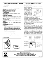
Napco's IBR-ITAB iBridge® touch screen tablet keypad is a high-
resolution LCD android tablet that
provides wireless access to all the
features of your alarm system.
The IBR-ITAB keypad is simple to
use, with its intuitive menu-driven
icons and prompts to help guide
you. The wall docking station pro-
vides charging to the IBR-ITAB's
internal battery (its integral charg-
ing circuit ensures automatic re-
charging as required). The décor-neutral IBR-ITABSTAND an-
gled tabletop stand and docking station provides charging and
convenient desktop usage, is ideal for bedrooms, kitchens, etc.
FEATURES
The IBR-ITAB keypad has many convenient features:
•Touch screen control of security system--and more--from
anywhere in the home
•Easy on/off magnetic wall mounting frame (IBR-ITABSTAND
angled tabletop stand and docking station also available)
•Integrated IP video viewing of iSee Video cameras
•Message Minder recordable voice messages
•Internet browser-enabled
•Handy on-screen tools including weather, calculator, etc.
•High-speed, powerful processor
•Large high-resolution 800 x 480 pixel display for clarity
•Intuitive touch screen display with icons and menu driven
prompts (English only)
•802.11 Wireless Wi-Fi Connectivity
•Digital picture frame or slideshow through a standard USB
memory stick / thumb drive
•Family Message Center - Record and playback messages for
family members Over two minutes of recordable time
•Entry/Exit countdown displayed
•Add or delete User Codes
•Quickly and easily bypass zones
•The IBR-ITAB Tablet Keypad is one part of the integrated
Napco iBridge® Remote Control Services that include:
•Virtual Keypad
•Z-Wave® Home Controls
•Integrated iSee Video
Compatible with the following control panels:
•Freedom F-64
•LIBRA-P432EX
•GEM-P816
•GEM-P1632
•GEM-P1664
•GEM-P3200
•GEM-P9600
•GEM-X255
Note: A standard wired keypad must be installed and enrolled
in the system before adding a IBR-ITAB keypad. Visit www.
napcosecurity.com for ordering information and evaluated Z-
Wave devices.
KEYPAD SPECIFICATIONS
Electrical Ratings
Battery: Integral Polymer Lithium-ion
Capacity: 1800mAh, 5-6 hours per charge
Speaker: 1 Integral 2W
Charger: 12VDC/2A DC Adapter, cable length 70" (180cm)
Electrical Ratings (Fully Discharged Battery)
Screen on, charging idle: 12VDC, 845mA
Clicking menu items: 12VDC, 945mA
Electrical Ratings (Fully Charged Battery)
Screen on, charging idle: 12VDC, 300mA
Clicking menu items: 12VDC, 380mA
Features
Hardware Platform: ARM11™ processor family
CPU: Samsung™ 65nm S3C6410 Mobile Processor CPU
1200MHz (up to 1.2GHz)
Frequency: 667-800MHz
RAM: 256MB DDR
ROM Flash: 1GB
Wi-Fi: 802.11b/g with built in Antenna
LCD Size: 7 inch digital screen
Resolution Ratio: 800 x 480 x 32 WVGA, 16:9 Wide Screen,
Color
Pixels: 260,000 million
Touch Screen: Digital and full-screen, Resistance
Microphone: Integral high sensitivity, voice input
External Card: Push-push type Micro SD Port, Max 32GB
USB Host Cable: USB A Female, for Mouse, keyboard HUB,
etc.
Video: Composite Video, 3.5mm to RCA Port
Firmware: Google Android 1.6
Audio: Compatible with WMA, MP3, WAV, AAC
Images: JPG (Max 2048x2048 pixels) with Slide Show
Video: MPEG-4/H.263/H.264
Housing
Dimensions (HxWxD): 7.5" x 4.7" x 0.4" (19cm x 12cmm x
10cm)
Weight: 11.6oz (330g)
Operating Temperature: 0-49ºC (32-120°F)
SELECTING THE MOUNTING LOCATION
Two items must be considered when planning the system layout:
1. The mounting location selected for the IBR-ITAB keypad
must permit a continuous wireless connection between the
IBR-ITAB keypad and the IBR-WIFI-MOD (see WI1942) or
the ISEE-WAP (see WI2049).
2. In addition, the wall-mounted Charging Station requires
IBR-ITAB
iBridge® Touch Screen Tablet Keypad
Installation and Mounting Instructions
WI1944E 06/13
IBR-ITAB Wireless
Touchscreen Tablet
R
333 Bayview Avenue
Amityville, New York 11701
For Sales and Repairs, (800) 645-9445
For Technical Service, (800) 645-9440
(Note: Technical Service is for security professionals only)
Publicly traded on NASDAQ Symbol: NSSC
© NAPCO 2013

2
power supplied from two wires intended to be hidden within
the mounting surface. These two wires are connected to a
power supply that can be plugged into any standard
120VAC outlet, such as in a basement or other distant loca-
tion. Note: Power wires are polarized, and MUST be in-
stalled as detailed in the installation instructions that follow.
To ensure a continuous wireless connection between the IBR-
ITAB keypad and the IBR-WIFI-MOD or ISEE-WAP, select a lo-
cation for the Charging Station that is within a reasonable dis-
tance from the IBR-WIFI-MOD or ISEE-WAP. Choose a location
as high above ground level as practical, keeping in mind that
metal objects may adversely affect reception. Although wood and
wallboard construction will have little effect upon signal strength,
concrete or brick can reduce signal strength by up to 35%, while
steel-reinforced concrete or metal lath and plaster can reduce sig-
nal strength as much as 90%.
Mount the IBR-ITAB keypad Charging Station indoors only, and
avoid high condensation areas such as bathrooms. Avoid mount-
ing in locations where direct sunlight or bright light shines directly
on the screen.
CHARGING STATION INSTALLATION
HOLLOW WALL
If installing into a 3-gang box, see instructions to the right. To
secure the Wall Mounting Plate directly to a hollow dry wall or
similar surface, proceed as follows:
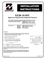
1. Select the mounting location preferably at eye level for easy
viewing by the user. Select a mounting location that allows
the power wires to be hidden within the mounting surface.
Furthermore, in the image below, note how the "Wire Hole in
Wall Mounting Plate" aligns with the "Wire Hole in Mounting
Surface". The two power wires are connected to the power
supply that is plugged into any standard 120VAC outlet lo-
cated in a basement or other distant location. IMPORTANT:
The positive power supply wire is marked with red heat
shrink tubing; be sure not to dislodge this red marking when
routing wires, as polarity MUST be maintained.
2. With the final mounting location selected, drill the power wire
hole in the mounting surface. Snake the two power wires
from the power supply source location into the interior of the
mounting surface (wall), then out through the power wire
hole drilled in the mounting surface.
3. Using wire nuts or connectors appropriate for the installation,
connect the red wire from the Wall Mounting Plate to the
positive power supply wire marked with the red heat shrink
tubing. Connect the black wire from the Wall Mounting Plate
to the other black power supply wire. If the red heat shrink
tubing was dislodged and you are uncertain as to the polar-
ity, use a voltmeter to determine the polarity. Push wires
into the power wire hole in the mounting surface, leaving the
Wall Mounting Plate flush against the mounting surface.
4. Use the Wall Mounting Plate as a template, marking the 6
screw holes with a pencil.
5. Drill 6 holes 3/16" diameter for mollies (anchors). Tap mol-
lies (anchors) into wall with hammer.
6. Secure Wall Mounting Plate to wall with six #6 x 1" long
sheet metal Phillips flat head Type A screws (part SC461).
7. To hide the screw heads installed in the previous step, a Fin-
ishing Cover Plate (HW1854) is provided. Firmly press the
Finishing Cover Plate into the Wall Mounting Plate until the
top and bottom snaps fully engage.
To enroll the IBR-ITAB into the security system using an
IBR-WIFI-MOD see WI1942; if using an ISEE-WAP see
WI2049.
CHARGING STATION INSTALLATION
3-GANG BOX
If installing the Wall Mounting Plate directly to a hollow dry wall
or similar surface, see instructions at left. To secure the Wall
Mounting Plate to a 3-gang box, proceed as follows:
1. Select the mounting location preferably at eye level for easy
viewing by the user. Reference the diagram below; with the
3-gang box installed, notice how the Wall Mounting Plate
two power wires are intended to run through the largest hole
in the Gang Box Insert into the 3-Gang Box. These two
power wires are connected to the two power wires from the
power supply that are routed into the 3-Gang Box. The
power supply is plugged into any standard 120VAC outlet
located in a basement or other distant location.
2. With the 3-Gang Box installed, snake the two power supply
wires from the transformer power source location into the 3-
Gang Box.
IMPORTANT: The positive power supply wire is marked
with red heat shrink tubing; be sure not to dislodge this red
marking when routing wires, as polarity MUST be main-
tained.
3. Run the Wall Mounting Plate two power wires through the
largest hole in the Gang Box Insert and into the 3-Gang Box.
Using wire nuts or connectors appropriate for the installation,
Hollow Wall Installations
"Wire
Hole in
Mounting
Surface"
"Wire Hole
in Wall
Mounting
Plate"
(9HW1836ASSY)
Wall Mounting
Plate
(SC461) #6 x 1" long
sheet metal Phillips
flat head Type A
screws (6)*
(HW1854)
Finishing
Cover
Plate
3-Gang Box Installations
(SC523)
Screws (6)
(HW1848)
Gang Box
Insert
3-Gang Box
(Installer provided)
(SC652) #6 x 1" long
Hi-Low Phillips flat
head screws (6)
(HW1854)
Finishing
Cover Plate
(9HW1836ASSY)
Wall Mounting
Plate

3
connect the red wire from the Wall Mounting Plate to the
positive power supply wire marked with the red heat shrink
tubing. Connect the black wire from the Wall Mounting
Plate to the other black power supply wire. If the red heat
shrink tubing was dislodged and you are uncertain as to
the polarity, use a voltmeter to determine the polarity.
4. Using the 6 screws (SC523), secure the Gang Box Insert
to the 3-Gang Box as shown in the illustration above. Hide
the screw heads with the 3/8" diameter circular white stick-
ers (LA3001) provided.
5. Secure the Wall Mounting Plate to the Gang Box Insert
with the six #6 x 1" long Hi-Low Phillips flat head screws
(part SC652) as shown in the illustration above. Hide
these screw heads with the Finishing Cover Plate
(HW1854). Firmly press the Finishing Cover Plate into the
Wall Mounting Plate until the top and bottom snaps fully
engage.
IBR-ZREMOTE
CUSTOMER ROUTER
(Wireless or Wired-only)
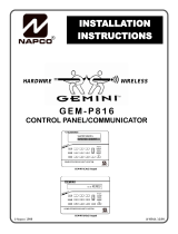
WIRING OVERVIEW with IBR-ZREMOTE and ISEE-WAP
KEYPAD BUS
BROADBAND
MODEM
TO PANEL SERIAL PORT (only
needed for IBR-ZREMOTE CS
communication or panel
downloading)
NETWORK
CONTROL
PANEL
STANDARD
KEYPAD
Internet
RED
BLACK
GREEN
YELLOW
GREEN
YELLOW
RED
BLACK
ISEE-WAP
IBR-ITAB-HW CAMERAS
(((
(((
IBR-ITAB
(
(
(
(((
NETWORK
(
(
(
(
(
(
Remote Services
(
(
(
Z-WAVE DEVICES
THE FOLLOWING STATEMENT IS REQUIRED BY THE FCC.
This equipment generates and uses radio-frequency energy and, if not installed and used
properly, that is, in strict accordance with the manufacturer's instructions, may cause
interference to radio and television reception. It has been type tested and found to comply with
the limits for a Class-B computing device in accordance with the specifications in Subpart J of
Part 15 of FCC Rules, which are designed to provide reasonable protection against such
interference in a residential installation.
However, there is no guarantee that interference will not occur in a particular installation. If this
equipment does cause interference to radio or television reception, which can be determined by
turning the equipment off and on, the user is encouraged to try to correct the interference by
one or more of the following measures: reorient the receiving antenna; relocate the computer
with respect to the receiver; move the computer away from the receiver; plug the computer into
a different outlet so that computer and receiver are on different branch circuits.
If necessary, the user should consult the dealer or an experienced radio/television technician
for additional suggestions. The user may find the following booklet prepared by the Federal
Communications Commission helpful: “How to Identify and Resolve Radio-TV Interference
Problems”. This booklet is available from the U.S. Government Printing Office, Washington, DC
20402; Stock No. 004-000-00345-4.

4
IBR-ITAB DEALER SETTINGS MENU
This "System Settings" button can display either a partial list of
"user-only" selections or a full list of "dealer-only" selections, de-
pending on the how this button is tapped and pressed:
•User Settings: To display the partial list of "user-only" se-
lections, simply tap this button once (see OI372)
•Dealer Settings: To display the full list of "dealer-only" se-
lections, press and hold this button (password required)
When accessing the "dealer-only" selections (again, by pressing
and holding this button), a popup appears requesting a pass-
word. This password request signifies that the Dealer Settings
menu will be displayed (detailed in this section). Type the IBR-
ITAB dealer password (default is "admin") and tap OK. Tap
Yes to the warning popup that appears, and the User Settings
menu opens. Note: For descriptions of the "user-only" selec-
tions, see the User Guide for the keypad (see OI372). For Z-
Wave menu selections, see the Using your iBridge® IBR-
ITAB Series Z-Wave® Home Automation System (OI378).
Dealer Settings > Security
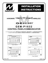
Keypad Skin - Select the keypad model type configured in the
IBR-ZREMOTE. Selections include:
Classic: Displays the IBR-ITAB proprietary keypad, with
extra large keys, modeled on the Gemini "GEM-RP1CAe2"
two-line display alpha keypad, as shown in the following im-
age:
K Series Stay / Away: Displays the IBR-ITAB proprietary
keypad with extra large keys, modeled on the Gemini
"GEM-K1CA" two-line display "K Series" Stay/Away alpha
keypad, as shown in the following image:
EZ-ARM - Check to enable Easy Arming (ability to arm the
alarm system quickly by simply tapping U or D). Each
keypad may be individually programmed for Easy Arm-
ing. Disarming still requires entry of a valid user code.
Note: Do not program Easy Arming in UL installations.
The alarm control panel must be programmed to support
this feature.
EASY EXIT - Check to enable Easy Exit. While armed in the
Interior Bypass/Stay Mode, Easy Exit can be
initiated by pressing and holding the Disarm
"pie wedge" button. Easy Exit restarts the Exit
delay (the top banner on the IBR-ITAB changes
to read "ARMING STAY...") allowing a User to
exit an armed premises without disarming and rearming
the system. Note: Do not program Easy Exit in UL in-
stallations. The alarm control panel must be pro-
grammed to support this feature.
Number of Zone Areas are - Some systems may be divided,
or partitioned, into smaller independent subsystems,
which are referred to as Areas. Tap to select the number
of Areas in the alarm system. Note: Each Area may be
controlled by its own keypad or by a keypad of a different
Area through Managers Mode (a low-security operating
mode that allows arming by area).
Connection Settings - Allows changes to be made to the net-
work communication and automatic identification settings
used between the IBR-ITAB and the ISEE-WAP. Changes
to these settings are rare; consult with the factory before
changing.
Serial Interface: Indicates status if hardwired.
IP Address: Set the private TCP/IP protocol address used
for communications between the IBR-ITAB and the ISEE-
WAP.
Port No.: Set the port number used for network activities
as set by the IBR-ZREMOTE.
Autodiscovery Options: Manage the automatic recogni-
tion and connection settings between the IBR-ITAB and the
IBR-ZREMOTE.
Autodiscovery: Check to enable ongoing automatic
recognition of and connection between the IBR-ITAB
and the ISEE-WAP.
Discover: Tap to initiate the discovery (recognition of
and connection) process between the IBR-ITAB and the
IBR-ZREMOTE, setting the IP address and Port shown
on the Connection Settings screen.
Autodiscovery Port Range Base: When the IBR-ITAB
and ISEE-WAP are establishing their initial handshake
connection, the ISEE-WAP establishes four (4) listening
ports for connection. This menu item allows the starting
port number used by the ISEE-WAP to be changed from
its default setting of 8000.
Time interval to request status: Tap to enter the duration
between autodiscovery process activations.
Log Settings - Allows changes to logs (system activity used for
backup/recovery and troubleshooting).
Logging: Tap to enable log files to be created.
Logcat: Tap to enable the Logcat command, allowing the
viewing of the internal log in the Android operating system.
Helpful with diagnosing and troubleshooting system issues.
IBR-ITAB Napco Security Application
"System Settings" Button
"K Series Stay / Away" Keypad Skin
"Classic" Keypad Skin

5
Maintain log file size: To keep the log file size within
30MB. When log file size exceeds 30MB, the IBR-ITAB
deletes those log entries stored for the longest time (first in,
first out).
Delete Log File: Tap to remove erase all entries in the log
file.
Show Log File - Tap to view the log file entries in the IBR-
ITAB.
Show Logcat - Tap to view the Android operating system
internal log entries.
Dealer Settings > Tablet > Screensaver Options
IBR-ITAB screen options that activate after a selected user
idle time duration (IBR-ITAB is operational but not being
used).
Screen dim timeout: Reduces the IBR-ITAB screen
brightness to zero (dark) after the selected duration ends
and the idle time duration begins (15 or 30 seconds, 1, 2, 5,
or 20 minutes). To disable the screen dim feature, select
"Never Timeout". Note: When this feature is enabled and
the screen dims, just touch the screen to restore the dis-
play.
Screen Darkness: Allows the selection of darkness per-
centage after the screen dim timeout duration starts. Often
used in bedroom locations. Selections range from 0% (no
dim/bright) to 100% (fully dim to black) in 10% increments.
Dealer Settings > Tablet > Connection
The following four (4) menu items are detailed in the section
"SECURE THE WIRELESS CONNECTION".
(1) Change/Create CUSTOM IBRIDGE ISEE-WAP SSID and
KEY: Select this feature to modify the factory default net-
work settings of the ISEE-WAP and IBR-ITAB. The Pre-
ferred Network dialog appears, allowing a new SSID and a
new secret Key to be entered, and the selection of either
WEP or WPA2 wireless encryption security protocol to be
used (we recommend using WPA2). Note that this informa-
tion can be changed at any time by re-running this feature.
Note: The ISEE-WAP and all wireless cameras in the sys-
tem must be unlocked before using this feature.
(2) Tablet Connection/SSID Choice: When first powered, by
default the IBR-ITAB automatically attempts to connect with
the first ISEE-WAP that answers using the default SSID of
"PUBLIC". This feature contains two selections, as follows:
•NAPCO IBRIDGE ISEE-WAP: Select to allow your
IBR-ITAB to attempt to connect with an ISEE-WAP using
the default SSID of "PUBLIC" and a blank Key (thus
matching the factory default settings of the ISEE-WAP).
•CUSTOM SETUP: Select to request your IBR-ITAB to
attempt to connect with an ISEE-WAP using the custom
SSID and secret Key previously created in the menu
item named "(1) Change/Create CUSTOM IBRIDGE ISEE-WAP
SSID and KEY" described above.
For more information about how the IBR-ITAB attempts to
connect with the ISEE-WAP, see "AUTO-DISCOVERY
PROCESS" earlier in this manual.
(3) Configure Wireless Camera: When wireless cameras are
first powered, they (by default) automatically attempt to con-
nect with the first ISEE-WAP that answers using the default
SSID of "PUBLIC". This feature requests all cameras within
range to attempt to connect with an ISEE-WAP using the
custom SSID and secret Key previously created in the
menu item named "(1) Change/Create CUSTOM IBRIDGE ISEE-
WAP SSID and KEY" described above. Note: All wireless
cameras in the system must be unlocked before using this
feature.
(4) Lock Down IBRIDGE ISEE-WAP: Tap to protect the ISEE-
WAP / IBR-ITAB connection by a "lock down" process, en-
suring a fixed connection between the ISEE-WAP / IBR-
ITAB device pairs. This selection disables the automatic
connection process that attempts to connect the IBR-ITAB
with the first ISEE-WAP that answers using the default
SSID of "PUBLIC".
Unlock IBRIDGE ISEE-WAP: To reverse the "Lock Down"
process described in the previous menu selection.
Minutes to check connection integrity: Tap to set the num-
ber of minutes the IBR-ITAB will automatically attempt a res-
toration of the wireless connection between the IBR-ITAB
and the ISEE-WAP should this connection be interrupted.
Selectable durations are: 1, 3, 5, 7, 10, 15 and 20 (minutes).
Force Tablet Reconnection Now: Text indicates current
status of the IBR-ITAB wireless connection. Regardless of
the current state of the connection, tap this option to force a
termination of the connection and to attempt a restoration.
When this selection is pressed, the menu items listed in the
WIFI settings menu selection appear (see below).
BSSID used to LOCKDOWN IBRIDGE: Tap to enter a new
"broadcast" SSID (named "BSSID" in this menu) to be
stored in the IBR-ITAB's memory, to be used by default
when the IBR-ITAB is rebooted, powered off/on or emerges
from Screen lock.
Dealer Settings > Tablet > System Settings
Date and Time:
Automatic: When checked to enable, retrieves IBR-ITAB
date/time data automatically from network resources.
When enabled, the next three selections are ghosted
("grayed out" and not selectable).
Set date: Tap to open a dialog that allows the month, day
and year to be manually set in the IBR-ITAB. Note: The
"Automatic" menu selection (above) must be unchecked to
enable this menu item.
Select time zone: Tap to select a time zone to be used in
the IBR-ITAB. Note: The "Automatic" menu selection
(above) must be unchecked to enable this menu item.
Set time: Tap to open a dialog that allows the current time
to be manually set in the IBR-ITAB. Note: The "Automatic"
menu selection (above) must be unchecked to enable this
menu item.
Use 24-hour format: Check to display 24-hour military
time, as measured in hours numbered to twenty-four from
(continued from previous page)
Dealer Settings > Security

6
one midnight to the next. For example, 3:23 pm would be
displayed as "15:23".
Select date format: Tap to open a dialog that allows the
selection of the following date formats:
•Normal (12/31/2011) (Month/Day/Year)
•12/31/2011 (Month/Day/Year)
•31/12/2011 (Day/Month/Year)
•2011/12/31 (Year/Month/Day)
Display - Allows changes to the IBR-ITAB display screen.
Brightness: Tap to open a sliding status bar control. In-
crease or decrease the screen brightness by sliding your
finger left or right across the status bar.
Auto-rotate screen: (Not Used; do not check this selec-
tion).
Animation: Tap to open a pull-down menu where you can
select "No animations" to disable all optional animation ef-
fects, "Some animations" to enable animated transitions
for some effects, or "All animations" for all supported ef-
fects including screen to screen navigation attributes. Note:
The "No animations" setting does not control animation in
all applications.
Screen timeout: Specifies how much user idle time (IBR-
ITAB is operational but not being used) must elapse before
the screen dims. The default setting is "never". Note:
When this feature is enabled and the screen dims, the IBR-
ITAB also enters "sleep mode", an inactive state to save
power. To re-awaken, touch any non-screen button.
Screen timeout selections include 15 seconds, 30 seconds,
1 minute, 2 minutes, 10 minutes, 30 minutes and never.
TV Mode: (Reserved for future use)
TV Resolution: (Reserved for future use)
TV HDCP: (Reserved for future use)
Language - Tap to select the language of the IBR-ITAB menus.
Sound - Controls sound intensity and feedback settings.
Volume: Tap to open a dialog containing sliding status bar
controls to set the Media volume, Alarm volume and Notifi-
cation volume intensity.
Feedback
Audible selection: Check to play a sound when certain
icons, keys, buttons and other onscreen items are
touched.
Screen lock sounds: Check to play sounds when the
IBR-ITAB display screen is locked or unlocked.
Haptic feedback: Check to briefly vibrate the IBR-ITAB
when certain icons, keys, buttons and other onscreen
items are touched (unavailable with some models)
Dealer Settings > Tablet > Auto Task Killer
Check to automatically kill all unnecessary tasks listed in the
Task Killer list during an alarm or other emergency situation.
Tasks include applications currently in use, and those run-
ning in the background ("hidden" tasks running "behind the
scenes"), such as operating system and network communi-
cation processes. See OI376, MENU BUTTON, Task Kil-
ler for more information.
Dealer Settings > Tablet > Restore Factory
Settings
Tap to restore the IBR-ITAB to the settings originally set at
the factory. Thus the IBR-ITAB is returned to its original
"out of box" condition.
Dealer Settings > Tablet > Update
Update Server Address: Displays the IP Address and Port
number used by the network server when the menu selec-
tion Check For Updates (described below) is tapped.
Source: Select the source of the new firmware files from
the following three selections:
•Internet: Select if the new firmware update is located
on the Internet;
•SD Card: Select if the new firmware update is located
on a secure digital microSD flash memory card, and
you wish to use the microSD Card Slot located on the
side of the IBR-ITAB. Note: The update file must be
placed in a folder named "napco" (case sensitive)
located in the top root directory. Note: The
"microSD" card format is also called "TransFlash";
•USB Drive: Select if the new firmware update is lo-
cated on USB memory (such as a thumb drive, portable
hard drive, memory stick, etc.), and you wish to use the
USB Socket located on the side of the IBR-ITAB.
Note: The update file must be placed in a folder
named "napco" (case sensitive) located in the top
root directory.
Check for Updates: Tap to automatically check to see if a
newer version of the IBR-ITAB firmware is available from
the location specified in the "Source" menu item (described
above). If a newer version is available, follow the on-screen
prompts to load the firmware update files, as necessary.
Current Version: Displays the current version number of
the IBR-ITAB firmware.
Napco Market: (Reserved for future use).
Update Logo: Insert a USB thumb drive to add your logo
image to the Home Screen and Keypad Skin. The logo
must be named "logo.png" (case sensitive) and must be lo-
cated in a folder named "dealerLogo" (case sensitive) lo-
cated at the top root directory of the thumb drive. When this
logo is added successfully and later the logo is tapped, the
IBR-ITAB opens its default browser to the webpage speci-
fied in the Update Infopage menu selection, detailed below.
Note: Although the IBR-ITAB searches for the specific file
name "logo.png", the image file itself may be a .png, .bmp
or .jpeg format. However, the file must be re-named "logo.
png".
Update Infopage: Insert a USB thumb drive to add an im-
age that will display website or other corporate information.
The file must be named "dealer.png" (case sensitive) and
must be located in a folder named "dealerLogo" (case sen-
sitive) located at the top root directory of the thumb drive.
When a logo is added to the Home Screen and Keypad
Skin using the Update Logo menu selection (see above)
and this logo is later tapped, the "dealer.png" image file will
appear enlarged on the IBR-ITAB screen.
Dealer Settings > Tablet > Password
Configuration
Allows you to change the password used to access the IBR-
(continued from previous page)
Dealer Settings > Tablet > System Settings

7
ITAB Dealer Settings menu. In the Change Settings
password popup that appears, press the empty field with
the flashing cursor to open an onscreen keyboard, allowing
you to type the new password. Check the optional "Show
password" checkbox to view the populated characters.
Press "Change Password" to enter or "Cancel" to exit
without changing. See page 6 "IBR-ITAB DEALER SET-
TINGS MENU" for more information.
Dealer Settings > Tablet > Android Settings
Do not use these settings.
Dealer Settings > Video
Use the Video menu to make changes to the video data
settings received by the IBR-ITAB.
Camera List
Camera Auto Discovery - Check to allow the IBR-ITAB to
automatically attempt to capture and display video stream
data found within the network to which the IBR-ITAB is con-
nected. This feature is designed to operate within the iSee-
Video system. See http://www.napcosecurity.com/video.
html for more information.
Configure Wireless Camera - Allows the IBR-ITAB to re-
motely change the wireless settings of the selected camera.
When this feature is selected, be aware that the network
path from the IBR-ITAB to the ISEE-WAP and to the cam-
era may take several seconds to be established. Note:
When selected, a popup appears, that reads:
"Please make sure to first connect an Ethernet cable
to the router and to then connect power to the cam-
era. Do you wish to proceed with Wireless Camera
Configuration?"
Plug one end of the USB to Ethernet adapter cable
(provided with the IBR-ITAB) to the USB Socket of the IBR-
ITAB, and the other end directly into the ISEE-WAP wire-
less panel interface module. In addition, the camera must
be powered and wirelessly connected to the network before
proceeding.
Tap Yes to proceed or No to exit without saving any
changes. If you tap Yes, the IBR-ITAB will scan the net-
work and all available cameras will be listed (by IP address)
in the Camera List that appears. Tap to select a camera in
the list, and a Configure Wireless Camera popup ap-
pears, allowing you to either Lock or Unlock the selected
camera. Locking the camera will ensure a permanent con-
nection between the camera and the IBR-ITAB.
Select either the Lock or Unlock radio button, and tap
Configure to proceed or tap Cancel to exit without saving
changes.
Camera Manual Discovery - Allows you to browse for and
select to use a specific camera attached to the iBridge net-
work using the IBR-ITAB. The following two steps
("Select…" and "Discover…" shown below are required:
•Select camera to discover: (Step 1): Tap to select the
camera you wish to discover and capture its video
stream data.
•Discover IP Camera: (Step 2): Tap to initiate the net-
work scanning process to discover the selected camera.
Upon discovery, the video will be available for display
from the IBR-ITAB Home Screen (Video button).
Discover All Cameras - Initiates the network scanning proc-
ess that discovers all cameras attached to the iBridge net-
work. Upon discovery, the video for the discovered cam-
eras will be available for display from the IBR-ITAB Home
Screen (Video button).
Dealer Settings > Home
Time Enable - Check to display the time in a numeric format on
the IBR-ITAB's Home Screen.
Weather Options - Local weather reports can be displayed on
the Home Screen.
Refresh Frequency: Tap to set how often to auto-
matically update the weather report feed. Selections
include 5, 10, 15, 20, 30, 40, 50, 70, 80, 90 and 100
minutes. More frequent updates increase data use and
slightly decrease battery life between charges.
Weather Feed: Check to display a weather report
feed on the Home Screen. Uncheck to remove the
weather feed from the Home Screen. Note: To cus-
tomize the weather report feed to a particular Zip
Code, see the following menu entries below.
Zip code entry: Check to associate the weather re-
port feed to the area of the United States specified
by the Zip Code entered in the field below. Uncheck
to disassociate the weather feed from this Zip Code.
Zip Code: Tap to set the Zip Code to which the
Weather Feed is associated.
Update Z-Remote Clock - Synchronizes the IBR-ZREMOTE
module internal clock with the same time as the IBR-
ITAB.
Dealer Settings > Reconnect
Tap for the IBR-ITAB to attempt to establish a valid connec-
tion to the network using its existing settings.
Dealer Settings > Modify Z-Wave Settings
(Optional) Check to enable the User Settings menu fea-
ture named "Z-wave", to allow control of the Z-Wave home
automation components within the system using the "User
Settings" menu (an IBR-ITAB Dealer password is not re-
quired). See the introductory text in this section "IBR-ITAB
DEALER SETTINGS MENU" for an explanation of the dif-
ferences between the list of "user-only" selections (User
Settings) and the full list of "dealer-only" selections (Dealer
Settings).
Dealer Settings > Emergency Button
(Optional) Check to enable the "E" (Emergency) button on
the IBR-ITAB Home Screen. If unchecked, the
"E" (Emergency) button on the IBR-ITAB Home Screen will
be disabled and the message, "Permission Denied.
Please Contact Dealer." will appear.
Dealer Settings > Change Login URL
Not Used; do not change this selection.

8
NAPCO SECURITY SYSTEMS, INC. (NAPCO) warrants
its products to be free from manufacturing defects in
materials and workmanship for thirty-six months following
the date of manufacture. NAPCO will, within said period,
at its option, repair or replace any product failing to
operate correctly without charge to the original purchaser
or user.
This warranty shall not apply to any equipment, or any
part thereof, which has been repaired by others,
improperly installed, improperly used, abused, altered,
damaged, subjected to acts of God, or on which any serial
numbers have been altered, defaced or removed. Seller
will not be responsible for any dismantling or reinstallation
charges.
THERE ARE NO WARRANTIES, EXPRESS OR
IMPLIED, WHICH EXTEND BEYOND THE
DESCRIPTION ON THE FACE HEREOF. THERE IS NO
EXPRESS OR IMPLIED WARRANTY OF
MERCHANTABILITY OR A WARRANTY OF FITNESS
FOR A PARTICULAR PURPOSE. ADDITIONALLY, THIS
WARRANTY IS IN LIEU OF ALL OTHER OBLIGATIONS
OR LIABILITIES ON THE PART OF NAPCO.
Any action for breach of warranty, including but not limited
to any implied warranty of merchantability, must be
brought within the six months following the end of the
warranty period. IN NO CASE SHALL NAPCO BE
LIABLE TO ANYONE FOR ANY CONSEQUENTIAL OR
INCIDENTAL DAMAGES FOR BREACH OF THIS OR
ANY OTHER WARRANTY, EXPRESS OR IMPLIED,
EVEN IF THE LOSS OR DAMAGE IS CAUSED BY THE
SELLER'S OWN NEGLIGENCE OR FAULT.
In case of defect, contact the security professional who
installed and maintains your security system. In order to
exercise the warranty, the product must be returned by
the security professional, shipping costs prepaid and
insured to NAPCO. After repair or replacement, NAPCO
assumes the cost of returning products under warranty.
NAPCO shall have no obligation under this warranty, or
otherwise, if the product has been repaired by others,
improperly installed, improperly used, abused, altered,
damaged, subjected to accident, nuisance, flood, fire or
acts of God, or on which any serial numbers have been
altered, defaced or removed. NAPCO will not be
responsible for any dismantling, reassembly or
reinstallation charges.
This warranty contains the entire warranty. It is the sole
warranty and any prior agreements or representations,
whether oral or written, are either merged herein or are
expressly cancelled. NAPCO neither assumes, nor
authorizes any other person purporting to act on its behalf
to modify, to change, or to assume for it, any other
warranty or liability concerning its products.
In no event shall NAPCO be liable for an amount in
excess of NAPCO's original selling price of the product,
for any loss or damage, whether direct, indirect,
incidental, consequential, or otherwise arising out of any
failure of the product. Seller's warranty, as hereinabove
set forth, shall not be enlarged, diminished or affected by
and no obligation or liability shall arise or grow out of
Seller's rendering of technical advice or service in
connection with Buyer's order of the goods furnished
hereunder.
NAPCO RECOMMENDS THAT THE ENTIRE SYSTEM
BE COMPLETELY TESTED WEEKLY.
Warning: Despite frequent testing, and due to, but not
limited to, any or all of the following; criminal tampering,
electrical or communications disruption, it is possible for
the system to fail to perform as expected. NAPCO does
not represent that the product/system may not be
compromised or circumvented; or that the product or
system will prevent any personal injury or property loss by
burglary, robbery, fire or otherwise; nor that the product or
system will in all cases provide adequate warning or
protection. A properly installed and maintained alarm may
only reduce risk of burglary, robbery, fire or otherwise but
it is not insurance or a guarantee that these events will not
occur. CONSEQUENTLY, SELLER SHALL HAVE NO
LIABILITY FOR ANY PERSONAL INJURY, PROPERTY
DAMAGE, OR OTHER LOSS BASED ON A CLAIM THE
PRODUCT FAILED TO GIVE WARNING. Therefore, the
installer should in turn advise the consumer to take any
and all precautions for his or her safety including, but not
limited to, fleeing the premises and calling police or fire
department, in order to mitigate the possibilities of harm
and/or damage.
NAPCO is not an insurer of either the property or safety of
the user's family or employees, and limits its liability for
any loss or damage including incidental or consequential
damages to NAPCO's original selling price of the product
regardless of the cause of such loss or damage.
Some states do not allow limitations on how long an
implied warranty lasts or do not allow the exclusion or
limitation of incidental or consequential damages, or
differentiate in their treatment of limitations of liability for
ordinary or gross negligence, so the above limitations or
exclusions may not apply to you. This Warranty gives you
specific legal rights and you may also have other rights
which vary from state to state.
NAPCO LIMITED WARRANTY
Important: iBridge is a trademark of Napco Security Technologies, Inc. All other trademarks, service marks, and product or service names described in this manual are for
identification purposes only and may be trademarks or registered trademarks of their respective owners. The absence of a name or logo in this document does not consti-
tute a waiver of any and all intellectual property rights that NAPCO Security Technologies, Inc. has established in any of its product, feature, or service names or logos.
/