NAPCO Gemini GEM-RP1CAe2 Installation Instructions Manual
- Category
- Fire protection
- Type
- Installation Instructions Manual
This manual is also suitable for

HARDWIRE WIRELESS
WI994A 10/99© Napco 1999
R
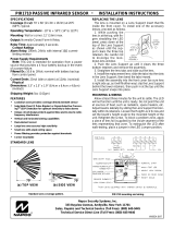
GEM-RP1CAe2 Keypad
R
ARMED
STATUS
NEXT/YES
PRIOR/NO
AREA
GEM-RP2ASe2 Keypad
R
ARMED
STATUS
NEXT/YES
PRIOR/NO
AREA

NAPCO Security Systems, Inc.
333 Bayview Avenue, Amityville, New York 11701
For Sales and Repairs, call toll free: (800) 645-9445
For direct line to Technical Service, call toll free: (800) 645-9440
Internet: http://www.napcosecurity.com

NAPCO Security Systems GEM-P816 Installation Instructions
WI994A 10/99
Page 3
Refer to accompanying GEM-P816 Programming Instructions (WI995) for programming information.
NOTE: THESE INSTALLATION INSTRUCTIONS ARE INTENDED AND WRITTEN FOR THE PROFESSIONAL INSTALLER HAVING SUITABLE
EXPERIENCE AND INSTALLATION EQUIPMENT. THE UNIT IS DESIGNED TO BE PROGRAMMED USING AN IBM-COMPATIBLE COMPUTER
WITH NAPCO PCD3000 SOFTWARE. AFTER PROGRAMMING, BE SURE TO RUN THE PCD3000 ERROR-CHECK UTILITY TO GUARD
AGAINST PROGRAMMING CONFLICTS FOR THE TYPE OF SERVICE SELECTED FOR THE INSTALLATION.
INTRODUCTION........................................................................................................................................................................................4
General Description..............................................................................................................................................................................4
Features................................................................................................................................................................................................4
Specifications........................................................................................................................................................................................6
Ordering Information.............................................................................................................................................................................7
Summary of UL Requirements..............................................................................................................................................................8
INSTALLATION .........................................................................................................................................................................................9
Mounting...............................................................................................................................................................................................9
Wiring....................................................................................................................................................................................................10
Wireless Systems.................................................................................................................................................................................10
Typical Residential Fire Installation......................................................................................................................................................10
Testing the System...............................................................................................................................................................................12
WIRING CONNECTIONS...........................................................................................................................................................................13
Battery ..................................................................................................................................................................................................13
Transformer..........................................................................................................................................................................................13
Siren/Bell Output...................................................................................................................................................................................13
Auxiliary Power.....................................................................................................................................................................................13
PGM Outputs........................................................................................................................................................................................13
Remote Bus..........................................................................................................................................................................................14
Earth Ground........................................................................................................................................................................................14
Basic Zone Configuration .....................................................................................................................................................................15
4-Wire Smoke Detectors.......................................................................................................................................................................16
2-Wire Smoke Detectors.......................................................................................................................................................................16
Telephone Lines...................................................................................................................................................................................17
KEYPAD CONFIGURATION MODE..........................................................................................................................................................18
Keypad Installation ...............................................................................................................................................................................18
Configuring the Keypads ......................................................................................................................................................................18
BASIC OPERATION ..................................................................................................................................................................................21
User Codes & Zone Descriptions .........................................................................................................................................................21
Arming and Disarming the System.......................................................................................................................................................22
Bypassing Zones..................................................................................................................................................................................24
Alarm Indication....................................................................................................................................................................................24
Function Mode......................................................................................................................................................................................25
Keypad Messages................................................................................................................................................................................26
GLOSSARY................................................................................................................................................................................................27
STANDBY-BATTERY CALCULATION WORKSHEET .............................................................................................................................43
WIRING LEGEND ......................................................................................................................................................................................44
KEYPAD PROGRAMMING MODES..........................................................................................................................................................45
WIRING DIAGRAM ....................................................................................................................................................................................49
FCC STATEMENT .....................................................................................................................................................................................51
LIMITED WARRANTY ...............................................................................................................................................................................52

GEM-P816 Installation Instructions NAPCO Security Systems
WI994A 10/99
Page 4
Napco's Gemini GEM-P816 is a state-of-the-art microcomputer-based burglary and residential fire alarm control panel of
modular design. Integrally an 8-zone panel, it will support up to 16 zones with the use of optional zone expansion modules,
wireless receiver modules and/or GEM-RP1CAe2 Keypads. Each panel includes an integral digital communicator.
Opening Suppression and Closing Suppression, available through Napco Quickloader software, suppress reporting within
programmed “windows”. Conversely, Exception Reporting can transmit a “fail to close” if the panel is not armed within
programmed intervals and, similarly, a “fail to open” if the panel is not disarmed within programmed intervals. Furthermore,
the panel can be programmed to automatically arm. A log containing up to 400 events (accessible through QuickloaderTM
software) monitors control-panel activity referenced to a precision real-time clock. A detailed event history may be
displayed at the computer, using Napco’s PCD3000 Quickloader Software.
Keypads feature a liquid-crystal display for messages. In normal use, the LCD shows zone identification and status
messages. Conventional LEDs and a sounder are also provided for annunciation.
Data may be quickly and easily downloaded to the control panel using a PC-compatible computer with Napco's PCD3000
Quickloader software and PCI2000 computer interface. Or, the panel may be programmed using the keypad in its
secondary mode of operation. In the keypad programming modes (there are two: Dealer and User), the LCD shows
memory address, data values, programming prompts, and the alphanumeric characters required for entering up to 16 user
codes and custom zone descriptions.
Control Panel Features
✔ Eight end-of-line-resistor burglary zones programmable.
✔ Supports up to 16 zones with optional zone-expansion modules, wireless receiver modules and 4-zone keypads.
✔ Supports up to 16 individually coded users, each with options.
✔ Supports three outputs (Bell, PGM1 and PGM2).
✔ Supports three keypad panics: Fire, Police & Auxiliary.
✔ Supports up to seven separate access stations (keypads) by up to 16 users.
✔ English-language prompts & system status messages.
✔ User-customized zone descriptions, re-programmable as required.
✔ Supports 2-wire and 4-wire smoke detectors.
✔ Reports alarms, restores and troubles by zone.
✔ 256 Event Log.
✔ Two programmable entry delay times.
NOTE: Failure to install and program as described in this manual for UL-listed systems voids the listing mark of
Underwriters Laboratories, Inc.
Features

NAPCO Security Systems GEM-P816 Installation Instructions
WI994A 10/99
Page 5
✔ Dynamic battery test interrupts charging and places battery under load every four hours.
✔ Chime by zone; programmable duration.
✔ Quickloader programmable.
✔ 2 PGM outputs.
✔ Supports Gemini Wireless Devices
Communicator Features
✔ Compatible with all major receiver formats, including 4/2, SIA and Point ID (except Radionics Modem II).
✔ Rotary dial and TouchToneTM with Rotary backup.
✔ Three 20-digit telephone numbers.
✔ Backup Reporting; Double Reporting; Split Reporting.
✔ 16 User Codes with Opening/Closing -Reporting by user.
✔ AC Failure Reporting with programmable report delay.
✔ Supervised Telephone Line.
✔ Pager capability.
✔ Report Alarms, Restores, Troubles and Trouble Restores by Zone.
✔ Supports Cancel Reporting.
Keypad Features
✔ English-language LCD display; LED and sounder annunciators.
✔ Supports up to seven 4-wire keypads.
✔ Provisions for fire, police and auxiliary panic alarms.
✔ Integral 4-zone EZM included in each keypad (GEM-RP1CAe2 only).
✔ Fault-Find diagnostics simplify troubleshooting.
✔ LEDs designate alarm/bypass status informatio.
✔ Sounder provides annunciation.
✔ Report alarms, restores, troubles and trouble restores by zone.
✔ Support cancel reporting.
Features

GEM-P816 Installation Instructions NAPCO Security Systems
WI994A 10/99
Page 6
GEM-P816
Operating Temperature:
0-49°C (32-120°F)
Input Power:
16.5-18.0 VAC via CLASS 2 Plug-In 20VA, 40VA or 50VA Transformer
Loop Voltage:
10-13Vdc
Loop Current:
3mA using a 2.2K Ohm end-of-line resistor (Model EOL2.2K); 5mA for 2-wire smoke-detector zones
Loop Resistance:
300 Ohm max.; 50 Ohm for 2-wire smoke-detector zones
Alarm Voltage Output: 1
Programmable Negative Outputs: 2
Auxiliary Power Output:
11.7-12.5 VDC
Remote Power Output:
12 VDC regulated (for keypads)
Combined Standby Current
(Remote Power + Aux. Power + Fire Power):
See following charts.
NOTE: (1) Alarm current can be increased by reducing standby current by the same amount.
* Not evaluated by U.L.
EZM Module:
GEM-EZM4/8: Input, 50mA
Keypad Current:
GEM-RP1CAe2: 100mA; 35mA if back lighting is disabled (cut W1, W2 & W3)
PGM Output: 5mA, 12V Special Application
Maximum Number of Keypads:
7
Maximum Wiring Length for each run (#22AWG): 1000' divided by total number of keypads and EZMs on run
Keypad Dimensions:
4” x 5” x 1” (HWD); 11.1cm x 14.9cm x 2.7cm (HWD)
RESIDENTIAL BURGLARY & COMMERCIAL BURGLARY
16.5VAC
TRANSFORMER BATTERY
(12 VDC) STANDBY
CURRENT ALARM
CURRENT STANDBY
TIME
40VA/50VA 7 AH 650 mA 2.0 A 4 Hours
20VA * 7 AH 500 mA 2.0 A 4 Hours
20VA * 7 AH 500 mA 2.0 A 6 Hours
RESIDENTIAL FIRE
16.5VAC
TRANSFORMER BATTERY
(12 VDC) STANDBY
CURRENT ALARM
CURRENT STANDBY
TIME
40VA/50VA 7 AH 120 mA 520 mA(1) 24 Hours
40VA/50VA * Two 7 AH 360 mA 280 mA(1) 24 Hours
20VA * 7 AH 120 mA 360 mA(1) 24 Hours
20VA * Two 7 AH 360 mA 120 mA(1) 24 Hours
RESIDENTIAL FIRE PROGRAMMING OPTION: Refer to GEM-P816 Programming Instructions (WI995) for program-
ming information. This option changes the operation of the power supply in alarm conditions to optimize performance. In
installations that do not monitor fire conditions (Residential and Commercial Burglary) U. L. allows the battery to be
depleted in alarm conditions when AC is present. To prevent the regulator and rectifier from exceeding 75% of their rated
temperature the regulator drops to 10V causing the battery to support the entire alarm current.In installations that do
monitor fire conditions (Residential Fire) U.L. does not allow the battery to be depleted in alarm conditions when AC is
present. Therefore when this bit is set the regulator is not dropped to 10V during alarm conditions. When this bit is set the
current specifications for Residential Fire should not be exceeded. If the specifications are exceeded when a 40VA or
50VA transformer is used the regulator may exceed 75% of its rated temperature up to 85% of its rated temperature at
which point the regulator will protect itself by current limiting. This would cause the battery to deplete, but no damage
would occur to the panel. If a 20VA transformer is used and the Residential Fire current specifications are exceeded then
the Transformer VA rating may be exceeded thereby damaging the transformer.
Specifications

NAPCO Security Systems GEM-P816 Installation Instructions
WI994A 10/99
Page 7
System Components
GEM-P816: Residential UL-Listed Burg and Fire Control
Panel.
GEM-P816M: Mercantile Burg
GEM-RP1CAe2: 32-Character LCD Burg & Fire Keypad
with 4 EOL Zones.
GEM-RP2ASe2: LCD Burg & Fire Keypad with remote
panic.
Optional Accessories and Peripherals
GEM-EZM4/8: 4-16 Zone Expansion Zone Module *
GEM-EVA 1: Electronic Voice Annunciator *
GEM-RECV8: Wireless Receiver, 8 Zones *
GEM-RECV16: Wireless Receiver, 16 Zones *
GEM-RECV96: Wireless Receiver, 96 Zones **
GEM-TRANS2: Window/Door Transmitter, 2-Point *
GEM-TRANS4: Window/Door Transmitter, 4-Point *
GEM-KEYF: Key Fob Transmitter *
GEM-SMK: Wireless Smoke Detector *
GEM-PIR: Wireless PIR *
GEM-DT: Wireless Dual-Technology Sensor *
GEM-GB: Wireless Glass-Break Detector *
M278: Line-Reversal Module
PS3002: Power-Supply Module, 13.2Vdc, 1.9A *
EOL2.2K: End-of-Line Resistor Assy., 2.2kW, for Fire
Circuit
FT2200: End-of-Line Relay/Resistor Supervisory Module *
RB1000: Relay Board *
RBATH1: Dual Battery Harness
RPB-3: Universal Junction Box
TRF11: Transformer, 16.5Vac/40VA, Class 2
TRF14: Transformer, 16.5Vac/50VA, Class 2
WL1: Wire Assembly with Lug Connector, 20”
VERI-PHONE: Two-Way Voice/Listen-In Module *
PCD3000: Downloading Software for IBM PC-Compatible
PCI2000/3000: Software with Interface for IBM PC-
Compatible Computer
PCI-MINI: Notebook Computer Interface
W834-1: Keypad Cable, plug-in (20”)
OI163: Instruction Manual, GEM-P816
OI192: Instruction Manual, GEM-RP2ASe2
OI193: Instruction Manual, GEM-RP1CAe2
WI995: GEM-P816 Programming Instructions
WIZARD IIe: Telephone Interface Module *
*Not investigated by UL.
**Limited to 16 Zones.
UL Listings
Household Burglar Alarm System Units: UL1023
Household Fire Warning System Units: UL985
Local Burglar Alarm Units and Systems: UL609 **
Central Station Burglar Alarm Units: UL1610 **
Police Station Alarm Units: UL365 **
** Pending
Ordering Information

GEM-P816 Installation Instructions NAPCO Security Systems
WI994A 10/99
Page 8
Note: * Voltage Rating: 8.5–13.3 VDC, Maximum Number of Detectors: 10
Residential
✔ Recognized Limited-Energy Cable for initiating, indicating and supplementary circuits.
✔ Initiating loops supervised if longer than 3 feet.
✔ FT2200 End-of-Line Relay for Fire (if using 4-wire smoke detectors).
✔ Minimum alarm timeout of 5 minutes.
✔ Maximum exit time: 60 seconds.
✔ Maximum entry time: 45 seconds.
✔ Do not program “Swinger Shutdown”, “Force Arming”, “Selective Bypass”, “Bypass”, or “50 ms Loop Response”.
✔ “Abort Delay” may not exceed 45 seconds.
✔ Program “Disable Callback Download”.
✔ Automatic dialer may not dial a police station number that has not been dedicated for such service.
✔ System must be tested at least weekly under AC/battery and Battery-Only conditions.
✔ Replace the rechargeable battery at least every 5 years.
✔ If the battery is heavily discharged, replace it or have it tested by a qualified technician.
✔ For silent panic, connect only to UL-listed holdup devices.
✔ All zones must be programmed for “Priority”.
✔ Do not program any zones for “Keyswitch Arming”.
✔ System must be serviced at least once every 3 years.
✔ Residential Fire and Combination Residential Fire & Burglary must program “Residential Fire”
✔ Keypad Expansion (EZM) Zones are not to be used as fire zones
✔ “Keypad Auxiliary” is not to be programmed for medical purposes.
✔ “System Trouble Audible Automatic Time-out” is not to be programmed.
✔ “Disable System Trouble Audible” is not to be programmed.
✔ “Easy programming of Auto download ID #'s and PC Preset Callback” is not to be programmed.
✔ “Sensor Watch” is not to be programmed.
UL Compatible Smoke Detectors (Providing UL Recognition or Listing)
Manufac-
turer 4-Wire
Smoke Detector 2-Wire
Smoke Detector * Smoke Detector
Base
Sentrol
System
Sensor
449AT
449C
449CRT
449CST
449CSRT
449CSRH
449CSST
449CLT
449CSLT
449CTE
741U
742U
1112
2112 2112T
2112TSRB
712U
722U
732U
711U
721U
721UT
731U
2100
2100T 1100
701U
702U
702RE
702RU
Smoke Detectors, 4-Wire:
1. ESL 445AT, 445C, 445CT, 445CR, 445CRT
2. Gentex 812, 812T, 812P, 812PT, 812PH; 8120, 8120T, 8120P, 8120PT, 8120PH
3. Hochiki America SLG-12 with YBC-RL4-RA Base
4. System Sensor 2312/24T; 1412; 1412TH; 2412TH
Subtract total smoke-detector alarm current from available standby current.
Note: Any normally-open devices that do not require power from the control panel, such as pull stations, waterflow and
thermostats may be used if acceptable to the Authority having Jurisdiction.
Summary of UL Requirements

NAPCO Security Systems GEM-P816 Installation Instructions
WI994A 10/99
Page 9
Control Panel
Choose a mounting location accessible to (a) a continuously-powered AC source, (b) system ground, a steel or copper
ground rod, ideally no further away than 10 feet, and (c) telephone lines (keep telephone wiring away from keypad wires).
Remove appropriate knockouts for cables. Place the control panel at a convenient viewing height and mark the mounting
holes. Attach the enclosure using screws suitable for the mounting surface.
Grounding
Connect the control-panel grounding screw to a long steel or copper ground rod driven deeply into the earth. Do not use
a gas pipe, plastic pipe or ac ground connections. Use at least 16-gauge wire. Make the run as short and direct as
possible, without any sharp bends in the wire.
Tamper Switches
Tamper switches may be installed to prevent opening of the control-panel door or removal of the cabinet from the wall.
Ideally, tamper switches should be connected to a zone that is active at all times, thus it may be necessary to program that
zone as a 24-Hour Zone or Day Zone. When used on a normally-open zone, normally-closed tamper switches (open
when set) should be wired in parallel. On a normally-closed zone, install Napco TPS-2 normally-open tamper switches
(closed when set) in series.
There are two places in the cabinet to mount tamper switches: (1) To prevent cabinet removal from the wall, there are
three mounting holes on the left side of the cabinet, another hole on the back that allows the switch button to contact the
wall. (2) To prevent opening the cabinet door, there are three mounting holes on the right side of the cabinet. When
mounted, the switch button should contact the inside of the door. Be sure to alert the user that opening the enclosure door
will cause a tamper alarm. Note: Each tamper switch is furnished with three machine screws for mounting, and one
self-tapping screw. The sole purpose of the self-tapping screw is to tap the holes for the machine screws; it may be
discarded after use.
Keypad
A keypad should be located near each exit/entry door. The keypad features a handy pull-up reference label. Before
mounting the keypad onto the wall, push the Sliding Label Plate (with label and felt backing affixed and handle facing
forward) down the guides at the rear of the keypad until it snaps into place. Once installed, the Sliding Label Plate cannot
be removed without first removing the keypad from the wall. Note: (1) The keypad fire and panic keys should not be
considered a substitute for a listed manual initiating device, such as a pull box. (2) Each GEM-RP1CAe2 includes
provisions for four additional zones. See ADDING EXPANSION ZONES.
If installing onto a double-gang box, insert mounting screws through the two vertical elongated holes on the left side of the
case and into the box. If the box is visible when viewed from the front, adjust the keypad vertically and tighten the screws.
Then, using hardware suitable for the mounting surface, add one or two screws at the right side of the keypad case
directly into the wall to ensure a secure installation. Note: Do not overtighten the screws! Uneven walls may cause the
keypad case to distort.
CAUTION: This equipment generates and uses radio-frequency energy. If not installed using conventional installation
practices for RF devices, it may cause interference to radio and television reception. It has been tested and found to
comply with the limits for a Class A computing device pursuant to Subpart B of Part 15 of FCC Rules, which are designed
to provide reasonable protection against such interference. However, there is no guarantee that interference will not occur
in a particular installation. If it has been found to cause interference to radio or television reception, which can be
determined by removing and reapplying AC and battery power to the equipment, the installer should try to correct the
interference by one or more of the following measures: reorient the receiving antenna; connect the power transformer to
a different outlet so that the control panel and receiver are on different branch circuits; relocate the control panel with
respect to the receiver.
Mounting

GEM-P816 Installation Instructions NAPCO Security Systems
WI994A 10/99
Page 10
Wire keypad(s), zones, expansion zone modules and output devices as shown on the Wiring Diagram. Note that the
Wiring Diagram contains important information not available elsewhere in this manual.
Adding Expansion Zones
GEM-P816 Series control panels will handle up to 8 zones as is, however this number may be increased to as many as
32 programmable zones using optional expansion zone modules (EZMs).
With the addition of at least one GEM-RECV series receiver, the GEM-P816 will support up to 16 wireless transmitters.
The panel can accommodate one or two receivers within the premises, responding to the one with the stronger transmitter
signal. If any transmitters are selected for the default program, a GEM-RECV receiver will automatically be programmed.
The keypad can display the status of any transmitter, indicating the condition of the zone (normal or open) and transmitter
troubles (low battery, tamper or supervisory failure), and signal strength of the last transmission. A receiver failure will be
indicated by “E06-NN” (“no response”, with NN representing the receiver number).
At least one smoke detector should be installed directly outside
each sleeping area. If there is more than one floor, additional
smoke detectors should be installed on each level, including the
basement. The living-area and basement smoke detectors should
be installed near the stairway of the next upper level.
For increased protection, additional detectors should be installed
in areas other than those required, such as the dining room,
bedrooms, utility room, furnace room, and hallways. Heat detec-
tors, rather than smoke detectors, are recommended in kitchens,
attics, and garages due to conditions that may result in false
alarms and improper operation. Large areas and areas with
partitions, ceiling beams, doorways, and open joists will require
additional detectors.
Refer to NFPA Standard No. 74 (National Fire Protection Associa-
tion, Batterymarch Park, Quincy, MA 02269) for additional information, including proper mounting of detectors.
CAUTION: Do not run telephone wiring near speaker wires; do not run keypad wiring with loop wiring.
Wiring

NAPCO Security Systems GEM-P816 Installation Instructions
WI994A 10/99
Page 11
THIS PAGE IS LEFT BLANK INTENTIONALLY.

GEM-P816 Installation Instructions NAPCO Security Systems
WI994A 10/99
Page 12
After installation is completed, test the system as follows.
1. Call the central station to inform them of the test.
2. Initiate an alarm, preferably on a zone that activates a steady siren, and verify proper signalling.
3. Call the central station to confirm their receipt of a good transmission.
Note: Be sure to test all enabled keypad panics.
Signal Strength Testing/Wireless Systems
To test the operation of wireless transmitters, proceed as follows. (Note: Wireless systems have not been investigated by
UL.)
1. Enter the Fault-Find Mode.
2. Fault a point of the transmitter to be tested by opening the loop. If the signal strength of the transmitter is 3 or
greater, the keypad will beep.
3. Restore the wireless point (close the loop). If the signal strength of the transmitter is 3 or greater, the keypad will
beep.
The transmitter signal strength will be displayed on a scale of 3-10 with 3 considered marginal and 10 considered
excellent. If the signal strength is less than 3, the keypad will not beep and the strength will be displayed. Except in the
Fault-Find Mode, signal strengths less than 3 will be entered into the system log.
Testing the System

NAPCO Security Systems GEM-P816 Installation Instructions
WI994A 10/99
Page 13
The RED (+) and BLACK (-) flying leads must be connected to
a 12VDC 4-7 AH Rechargeable Battery, to serve as backup
power in the event of AC Power Failure. NOTE: To calculate
the available standby time refer to the Standby-Battery Calcula-
tion Worksheet at the back of this manual.
Connect a 16.5 VAC Transformer to Terminals 1 and 2, using a wire of #18 AWG. or
less at a distance of 15 ft. or less from the control panel. NOTE: Do not connect to a
switched outlet.
Connect the alarm sounding devices (self-contained sirens,
speakers or a mechanical bells) to Terminals 3 and 4. Any
self-contained siren requiring a 12 VDC input can be connected.
When connecting a mechanical bell, it must be supervised using
a 2.2k Ohm resistor. To connect 8 Ohm Speakers use a Siren
Driver with the proper polarity observed. NOTE: Refer to the
GEM-P1632 Wiring Diagram for alarm current specification.
Connect the auxiliary devices (motion detectors, glass breaks, etc.) to Terminals 5 and 6.
Auxiliary Power provides 11.7-12.5 VDC nominal output which is used for powering auxiliary
devices. NOTE: To calculate the available standby time refer to the Standby-Battery
Calculation Worksheet at the back of this manual.
!"
PGM1 and PGM2 are negative switched pro-
grammable outputs that can be activated depending
on the programming options selected (see GEM-
P816 Programming Instructions). Connect the de-
vice controlled by the programmable output be-
tween terminal 5 (+) and the PGM output (-), either
terminal 7 or 8. As an example, the connection to
the RB1000 Relay Module is shown.
7
Wiring Connections: Battery, Transformer, Siren Power, Aux. Power & PGM Outputs

GEM-P816 Installation Instructions NAPCO Security Systems
WI994A 10/99
Page 14
ADDITIONAL
EZMs
AVAILABLE DEVICES
1. KEYPADS: GEM-RP2AS & GEM-RP1CAe2
2. X-10 INTERFACE: GEM-X10
3. WIRED ZONE EXPANDER: GEM-EZM816
4. WIRELESS RECEIVERS: GEM-RECV8, GEM-RECV16 & GEM-RECV96
5. RELAY MODULE: RM3008
6. VOICE INTERFACE: GEM-EVA
7. TELEPHONE INTERFACE: WIZARD2
(GEM-RP1CAe2)
2 LINE KEYPAD
REMOTE BUS
NOTE: Refer to the EZM Installation Instructions for specific
wiring information.
Connect the available devices as shown above to the remote bus terminals (9, 10, 11 & 12). Observe the correct color
wire connections. When connecting a keypads, first configure them accordingly (refer to the Keypad Configuration Mode
at the back of this manual). Keypads should be located near every exit/entry door. Up to seven keypads may be
connected if the longest cable run from the panel, to the farthest keypad (daisy chained or home-run) is less than 1000
feet. The maximum distance for seven keypads is 300 feet using 22 AWG. wire. NOTE: When running keypad wire, avoid
wiring parallel to other types of wiring.
NOTE: Do not use a gas pipe, plastic
pipe or AC ground connections.
Connect the control panel EARTH GROUND screw to a metal cold-water
pipe using at least a #16 AWG. wire. Do not use a gas pipe, plastic pipe or
AC ground connections. Also, connect the circuit board to the metal enclo-
sure. Connect a wire with a ground lug crimped or soldered onto one end of
the EARTH GROUND screw to the cabinet. NOTE: Grounding connections
should avoid bends in the grounding wire whenever possible.
Wiring Connections: Remote Bus & Earth Ground
R
ARMED
STATUS
NEXT/YES
PRIOR/NO
AREA
AVAILABLE DEVICES
1.
KEYPADS:
GEM-RP1CAe2, GEM-RP2ASe2 (7 maximum)
2.
WIRED ZONE EXPANDER:
GEM-EZM4/8 (16 zones maximum)
3.
WIRELESS RECEIVERS:
GEM-RECV8, GEM-RECV16
(16 zones maximum)
4.
VOICE INTERFACE:
GEM-EVA 1
5.
TELEPHONE INTERFACE:
WIZARD IIe

NAPCO Security Systems GEM-P816 Installation Instructions
WI994A 10/99
Page 15
#
The basic zone configuration for the GEM-P816 is 8 zones. Connect as shown above to terminals 13-24. Normally
Closed (N.C.) devices may be wired in series or Normally Open (N.O.) devices may be wired in parallel. Use the 2.2K
Ohm end-of-line (E.O.L.) resistor in each zone, if selected in programming (refer to the GEM-P816 Programming Instruc-
tions). Zones 1-8 can be selected for a “Fast Loop Response (50 ms)” or a “Normal Loop Response (750 ms)”. Other
zone options include Zone Type (Entry/Exit, Interior, 24 Hour Protection, Trouble and Fire), Instant, Chime, Area Selec-
tion and PGM Output selection.
(-)
Wiring Connections: Basic Zone Configuration

GEM-P816 Installation Instructions NAPCO Security Systems
WI994A 10/99
Page 16
2-WIRE SMOKE
DETECTOR WIRING
The GEM-P816 can use conventional 12 VDC 4-wire
smoke detectors. To use them, select fire zone pro-
gramming option and do not select 2-wire smoke detec-
tor programming option for the desired fire zone (refer
to the GEM-P816 Programming Instructions). Set JP3
to the position as shown, if zones 7 or 8 are to be used.
Two-wire smoke detectors can only be connected to zones 7 and 8. To use them,
select fire zone programming option and select 2-wire smoke detector program-
ming option for the desired fire zone 7 or 8 (refer to the GEM-P816 Programming
Instructions) and set JP3 to the position as shown. Connect the 2-wire smoke
detectors as shown.
If Fire Alarm Verification is desired to reset the smoke detectors, select this option
for the desired fire zone (zone 7 or 8).
$%
"%
Wiring Connections: 4-Wire Smoke Detectors & 2-Wire Smoke Detectors
4-WIRE SMOKE DETECTOR WIRING
The GEM-P816 can use conventional 12 VDC 4-wire smoke detectors. To use them,
the select fire zone programming option and do not select 2-wire smoke detector
programming option for the desired fire zone (refer to the GEM-P816 Programming
Instructions). Set JP3 to the position as shown, if zones 7 or 8 are to be used.
Four wire smoke detectors may be connected to any programmed fire zone (1-8) as
shown, within the panel. If external EZMs are used for zones 9-16, then 4-wire
smoke detectors may be connected to any programmed fire zones (9-16).
Power must be obtained from terminal 25 and 6. If Fire Alarm Verification is desired
to reset the smoke detectors, select this option for the desired fire zone.

NAPCO Security Systems GEM-P816 Installation Instructions
WI994A 10/99
Page 17
Wiring Connections: Telephone Lines
Model 368 Cord
Connect the Model 368 Cord as follows: 26 (RED = Telco Ring), 27 (GREEN = Telco Tip), 28 (GRAY = Home Ring) and
29 (BROWN = Home Tip). Insert the modular plug into an approved USOCRJ31X jack (or a CA31A jack for Canadian
installations). The Telco Line is used by the control panel to dial the central station and for downloading. This line should
not be connected to party lines or coin operated telephones. If connected to a line with call waiting, then call waiting
interrupt numbers must be programmed into the CS Telephone Numbers (refer to the GEM-P816 Programming
Instructions).
RING TIP TIPRING
TIP
RING

GEM-P816 Installation Instructions NAPCO Security Systems
WI994A 10/99
Page 18
This section will focus on configuring the GEM-RP1CAe2 and GEM-RP2ASe2 Keypads. If there is more than one keypad in the sys-
tem,
only Keypad No. 1 may be used for programming.
%
Two types of keypads may be used with the GEM-P816: the GEM-RP1CAe2 and the GEM-RP2ASe2. Each must be assigned an
address number (1–7) and each requires its own configuration procedure (see CONFIGURING THE KEYPADS, which follows, and
DIRECT ADDRESS KEYPAD AREA OPTIONS). At least 1 keypad must be used; only 1 is required for a single-area Commercial
Burglary installation.
GEM-RP1CAe2 - is a 2-line combination fire/burglary/access keypad capable of supporting 4 EZM zones and a PGM output. A
GEM-RP1CAe2 is recommended for use as Keypad #1.
GEM-RP2ASe2 - is a utility LCD keypad combining several preset LCD words with a limited message line. NOTE: Due to space con-
straints, available messages are abbreviated and will scroll automatically.
%
A total of up to 7 keypads may be connected to the panel. GEM-RP1CAe2 and GEM-RP2ASe2 keypads may be intermixed but re-
quire different configuration procedures, as described in the following paragraphs.
Configuring the GEM-RP1CAe2 Keypad
Each GEM-RP1CAe2 keypad must be configured for (a) keypad tactile beep; (b) entry sounder; (c) keypad address; (d) compatibility
number; (e) EZM address; and (f) zone response.
To enter the GEM-RP1CAe2 Confi
g
uration Mode:
1. Move jumper JP1 (located at the upper center of the control panel board) from Pins 1-2 (top two) to Pins 2-3
(bottom two). NOTE: See the Wiring Diagram.
2. After about 15 seconds, the display will read “ ”, where XX indicates the keypad address.
3. Press and proceed as follows. (Repeat the following procedure
for all keypads.)
Keypad Tactile Beep
Upon entering the Keypad Configuration Mode, “ ” will be displayed,
indicating that the tactile beep, which sounds when any button is pressed, is on. To
turn off the tactile beep, press the button (the button will toggle the tactile
beep on and off).
Press the button to continue or press the button to exit.
Entry Sounder
To turn off the keypad sounder during entry time, press the button (the but-
ton will toggle the tactile beep on and off). Press the button to continue or
press the button to exit.
Keypad Address
If more than one keypad is installed, each must be assigned a unique keypad ad-
dress (that is, no two keypads may be numbered alike):
keypads must be numbered consecutively (missing numbers are not permitted)
only Keypad No. 1 may be used for programming.
To assign the keypad number, proceed as follows:
1. Enter the assigned keypad number 01–07, then press the button to save. A valid number will be acknowledged by a short
beep; an invalid number will be rejected by a long beep.
2. Press the button to continue or press the button to exit.
NORMAL
KEYPAD
CONFIGURE
R
ARMED
STATUS
NEXT/Y ES
PRIOR/ NO
AREA
Keypad Configuration Mode

NAPCO Security Systems GEM-P816 Installation Instructions
WI994A 10/99
Page 19
Compatibility Number (Not Applicable)
THIS FEATURE IS NOT COMPATIBLE WITH THE GEM-P816 CONTROL
PANEL.
Press the button to continue or press the button to exit.
EZM Address
The keypad's internal EZM (Expansion Zone Module) may be utilized to
provide four additional wired zones. Whether used alone or in conjunction
with optional GEM-EZM series modules or other keypad EZMs, it must be
assigned a unique address (or Group number, see Keypad Programming
Workbook) similar to its keypad address. If no other EZMs are to be used, designate the keypad as Group “01” at the “
” display. In multiple-EZM systems, enter an assigned group number “01” through “02”. (Each EZM must
have a unique assigned group number, starting with “01” and proceeding consecutively.) Press the button to
continue or press the button to exit.
Zone Response
The normal loop response of each keypad expansion zone is 750mS,
however the response time of any zone can be reduced to 50mS as follows.
1. Of the following, circle the number(s) in parentheses associated with the
zone(s) to be changed:
Zone 1=(1); Zone 2=(2); Zone 3=(4); Zone 4=(8)
2. Add up the circled numbers.
3. At the keypad, enter the sum as a two-digit number “01” through “15” on the display, then press the button.
Example.
Change Zones 2, 3 and 4 to 50mS response.
1. Circle numbers for Zones 2, 3 and 4: (2), (4) and (8).
2. Add up the circled numbers: 2 + 4 + 8 = 14.
3. Enter “14” at the keypad, then press the button.
Press the button to continue or press the button to exit.
Program Control Message (Not Applicable)
THIS FEATURE IS NOT COMPATIBLE WITH THE GEM-P816 CONTROL
PANEL.
Press the button to continue (the display will loop back through selections, for changes) or press the button
to exit the Keypad Configuration Mode (display will read “ ”). Then replace Jumper JP1 across Pins 1–2
(top two).
Keypad Configuration Mode

GEM-P816 Installation Instructions NAPCO Security Systems
WI994A 10/99
Page 20
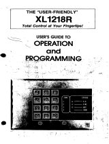
Configuring the GEM-RP2ASe2 Keypad
Up to 7 GEM-RP2ASe2 keypads may be connected to the panel (Keypads 1–7). Each must be configured for a keypad
address. In addition, the keypad may be configured to disable (a) touchpad backlight; (b) LCD backlight; and (c) entry
sounder. Keypads are configured by the proper selection of jumpers. Refer to the label on the circuit board fishpaper
(LA1390) for jumper locations and a summary of settings.
KEYPAD ADDRESS
If more than one keypad is installed:
Each must be assigned a unique address (that is, no two keypads may be
numbered alike).
Keypads must be addressed consecutively (that is, missing numbers are not
permitted).
Only Keypad No. 1 may be used for programming. (However, for ease of
programming, it is recommended that a GEM-RP1CAe2 be selected as Keypad
#1.)
Assign the keypad address number by selecting Jumpers J1–3 in accor-
dance with the table at left.
*Note: (1) Keypads are factory supplied with no jumpers installed and a as
such are automatically configured as Keypad No. 1. (2) Only one keypad in
the system may be configured as Keypad No. 1, otherwise none will func-
tion.
TOUCHPAD BACK LIGHT
Cut Jumper A to disable touch pad backlighting to conserve 11mA standby current.
LCD BACKLIGHT
Cut Jumper B to disable LCD backlighting.
DISABLE SOUNDER
Cut Jumper C to disable the sounder. (Do not disable in UL applications.)
KEYPAD
NUMBER
1
2
3
4
5
6
7
123
OFF or
ON* OFF OFF
OFF ON OFF
ON ON OFF
OFF OFF ON
ON OFF ON
OFF ON ON
ON ON ON
KEYPAD NUMBER
PARK
STORE SPARE
JUMPER AT THIS
POSITION
Keypad Configuration Mode
NAPCO Security Systems, Inc.
333 Bayview Avenue, Amityville, New York 11701
For Sales and Repairs, call toll free: (800) 645-9445
For direct line to Technical Service, call toll free: (800) 645-9440
Internet: http://www.napcosecurity.com
Page is loading ...
Page is loading ...
Page is loading ...
Page is loading ...
Page is loading ...
Page is loading ...
Page is loading ...
Page is loading ...
Page is loading ...
Page is loading ...
Page is loading ...
Page is loading ...
Page is loading ...
Page is loading ...
Page is loading ...
Page is loading ...
Page is loading ...
Page is loading ...
Page is loading ...
Page is loading ...
Page is loading ...
Page is loading ...
Page is loading ...
Page is loading ...
Page is loading ...
Page is loading ...
Page is loading ...
Page is loading ...
Page is loading ...
Page is loading ...
Page is loading ...
Page is loading ...
-
 1
1
-
 2
2
-
 3
3
-
 4
4
-
 5
5
-
 6
6
-
 7
7
-
 8
8
-
 9
9
-
 10
10
-
 11
11
-
 12
12
-
 13
13
-
 14
14
-
 15
15
-
 16
16
-
 17
17
-
 18
18
-
 19
19
-
 20
20
-
 21
21
-
 22
22
-
 23
23
-
 24
24
-
 25
25
-
 26
26
-
 27
27
-
 28
28
-
 29
29
-
 30
30
-
 31
31
-
 32
32
-
 33
33
-
 34
34
-
 35
35
-
 36
36
-
 37
37
-
 38
38
-
 39
39
-
 40
40
-
 41
41
-
 42
42
-
 43
43
-
 44
44
-
 45
45
-
 46
46
-
 47
47
-
 48
48
-
 49
49
-
 50
50
-
 51
51
-
 52
52


NAPCO Gemini GEM-RP1CAe2 Installation Instructions Manual
- Category
- Fire protection
- Type
- Installation Instructions Manual
- This manual is also suitable for
Ask a question and I''ll find the answer in the document
Finding information in a document is now easier with AI
Related papers
-
 NAPCO EXPRESS XP-600 User manual
-
 NAPCO EXPRESS XP-600 User manual
-
 NAPCO XP-400 Using Instruction
-
 NAPCO SECURITY COMMAND CENTER Operating instructions
-
NAPCO ISECHUB User manual
-
 NAPCO PIR1710 Installation guide
-
 NAPCO LIBRA LIB-P432EXT-230 Installation Instructions Manual
-
 NAPCO Gemini GEM-K2AS Installation Instructions Manual
-
 Napco Security Technologies GEM-P816 User manual
-
 NAPCO SLE-WIFI-MODULE Installation guide


Other documents
-
Honeywell LYNX Touch SIA User manual
-
Gemini GEM-RP8 Operating instructions
-
 Napco Security Technologies Gemini GEM-P1664 User manual
-
Pima Hunter-Pro 832 Programming Steps
-
 FBI XL1218R User manual
-
Visonic CL-80 Installation guide
-
Climax PB-23 User manual
-
FBII XL-20 Hookup And Installation Instructions
-
 Napco Security Technologies WI1501A User manual
-
 JR Security Systems centrum KD2 VR User manual


