Page is loading ...

IDC 255 Progate Drive Thru Installation Manual
INSTALLATION MANUAL
IDC 255 PROGATE DRIVE THRU UNIT
Release Date: December 31, 2008 www.cornelius.com Revision: B

IDC 255 Progate Drive Thru Installation Manual
Publication Number: 621057419INS - 2 - © 2006, IMI Cornelius Inc.

IDC 255 Progate Drive Thru Installation Manual
Safety Instructions. . . . . . . . . . . . . . . . . . . . . . . . . . . . . . . . . . . . . . . . . . . . . . . . . . . . . . . . . . . . . . . . 1
Read and Follow all Safety Instructions. . . . . . . . . . . . . . . . . . . . . . . . . . . . . . . . . . . . . . . . . . . . . . 1
Recognize Safety Alerts. . . . . . . . . . . . . . . . . . . . . . . . . . . . . . . . . . . . . . . . . . . . . . . . . . . . . . . 1
Different Types of Alerts. . . . . . . . . . . . . . . . . . . . . . . . . . . . . . . . . . . . . . . . . . . . . . . . . . . . . . . 1
Safety Tips. . . . . . . . . . . . . . . . . . . . . . . . . . . . . . . . . . . . . . . . . . . . . . . . . . . . . . . . . . . . . . . . . 1
Qualified Service Personnel. . . . . . . . . . . . . . . . . . . . . . . . . . . . . . . . . . . . . . . . . . . . . . . . . . . . 1
CO2 (Carbon Dioxide) Warning. . . . . . . . . . . . . . . . . . . . . . . . . . . . . . . . . . . . . . . . . . . . . . . . . 1
Shipping And Storage . . . . . . . . . . . . . . . . . . . . . . . . . . . . . . . . . . . . . . . . . . . . . . . . . . . . . . . . 1
Unit Specification. . . . . . . . . . . . . . . . . . . . . . . . . . . . . . . . . . . . . . . . . . . . . . . . . . . . . . . . . . . . . . . . . 2
Description. . . . . . . . . . . . . . . . . . . . . . . . . . . . . . . . . . . . . . . . . . . . . . . . . . . . . . . . . . . . . . . . . . . . 2
Valve Configurations . . . . . . . . . . . . . . . . . . . . . . . . . . . . . . . . . . . . . . . . . . . . . . . . . . . . . . . . . . . . 2
Specification. . . . . . . . . . . . . . . . . . . . . . . . . . . . . . . . . . . . . . . . . . . . . . . . . . . . . . . . . . . . . . . . . . . 2
Progate 2 Features . . . . . . . . . . . . . . . . . . . . . . . . . . . . . . . . . . . . . . . . . . . . . . . . . . . . . . . . . . 3
Progate Portion Ice Control Features. . . . . . . . . . . . . . . . . . . . . . . . . . . . . . . . . . . . . . . . . . . . . . . . . 3
Lid Dispenser. . . . . . . . . . . . . . . . . . . . . . . . . . . . . . . . . . . . . . . . . . . . . . . . . . . . . . . . . . . . . . . . . . . 3
Straw Holder . . . . . . . . . . . . . . . . . . . . . . . . . . . . . . . . . . . . . . . . . . . . . . . . . . . . . . . . . . . . . . . . . . . 3
Installation . . . . . . . . . . . . . . . . . . . . . . . . . . . . . . . . . . . . . . . . . . . . . . . . . . . . . . . . . . . . . . . . . . . . . . 4
Mounting and Placement. . . . . . . . . . . . . . . . . . . . . . . . . . . . . . . . . . . . . . . . . . . . . . . . . . . . . . . . . 4
Adjust Carbonator CO2 Regulator and Turn Water Inlet Supply Line ON. . . . . . . . . . . . . . . . . . . . 6
CO2 Installation . . . . . . . . . . . . . . . . . . . . . . . . . . . . . . . . . . . . . . . . . . . . . . . . . . . . . . . . . . . . . . . . 7
Power Installation. . . . . . . . . . . . . . . . . . . . . . . . . . . . . . . . . . . . . . . . . . . . . . . . . . . . . . . . . . . . . . . 7
Water Installation. . . . . . . . . . . . . . . . . . . . . . . . . . . . . . . . . . . . . . . . . . . . . . . . . . . . . . . . . . . . . . . 8
To access cold plate water inlets. . . . . . . . . . . . . . . . . . . . . . . . . . . . . . . . . . . . . . . . . . . . . . . . 8
Operation Instructions . . . . . . . . . . . . . . . . . . . . . . . . . . . . . . . . . . . . . . . . . . . . . . . . . . . . . . . . . . . . 9
Lid Dispenser Operation . . . . . . . . . . . . . . . . . . . . . . . . . . . . . . . . . . . . . . . . . . . . . . . . . . . . . . . . . 9
Unit Operation . . . . . . . . . . . . . . . . . . . . . . . . . . . . . . . . . . . . . . . . . . . . . . . . . . . . . . . . . . . . . . . . . 9
Loading of Lid Dispenser. . . . . . . . . . . . . . . . . . . . . . . . . . . . . . . . . . . . . . . . . . . . . . . . . . . . . . . . 10
Plastic Wrapped lids. . . . . . . . . . . . . . . . . . . . . . . . . . . . . . . . . . . . . . . . . . . . . . . . . . . . . . . . . 10
Individual lids . . . . . . . . . . . . . . . . . . . . . . . . . . . . . . . . . . . . . . . . . . . . . . . . . . . . . . . . . . . . . . 11
Lid Dispenser Operation . . . . . . . . . . . . . . . . . . . . . . . . . . . . . . . . . . . . . . . . . . . . . . . . . . . . . . . . 12
Lid Dispenser Maintenance . . . . . . . . . . . . . . . . . . . . . . . . . . . . . . . . . . . . . . . . . . . . . . . . . . . . . . 12
Progate 2 Control Box Operation. . . . . . . . . . . . . . . . . . . . . . . . . . . . . . . . . . . . . . . . . . . . . . . . . . 12
Portion Control Box Functions . . . . . . . . . . . . . . . . . . . . . . . . . . . . . . . . . . . . . . . . . . . . . . . . . 12
Programming (Changing) the Ice Portion . . . . . . . . . . . . . . . . . . . . . . . . . . . . . . . . . . . . . . . . 13
Agitation Time . . . . . . . . . . . . . . . . . . . . . . . . . . . . . . . . . . . . . . . . . . . . . . . . . . . . . . . . . . . . . 14
Programming (Changing) the Agitation Time. . . . . . . . . . . . . . . . . . . . . . . . . . . . . . . . . . . . . . 15
Ice Portion Bar . . . . . . . . . . . . . . . . . . . . . . . . . . . . . . . . . . . . . . . . . . . . . . . . . . . . . . . . . . . . . 16
Diagrams. . . . . . . . . . . . . . . . . . . . . . . . . . . . . . . . . . . . . . . . . . . . . . . . . . . . . . . . . . . . . . . . . . . . . . . 17
Cold Plate . . . . . . . . . . . . . . . . . . . . . . . . . . . . . . . . . . . . . . . . . . . . . . . . . . . . . . . . . . . . . . . . . . . 17
7 Intelli Valves and 1 Variety Valve . . . . . . . . . . . . . . . . . . . . . . . . . . . . . . . . . . . . . . . . . . . . . 17
5 Intelli Valves and 3 Variety Valves . . . . . . . . . . . . . . . . . . . . . . . . . . . . . . . . . . . . . . . . . . . . 18
8 Intelli Valves or 8 UFB-1 Valves . . . . . . . . . . . . . . . . . . . . . . . . . . . . . . . . . . . . . . . . . . . . . . 19
E – Board Off Cycle Agitation Adjustments . . . . . . . . . . . . . . . . . . . . . . . . . . . . . . . . . . . . . . . . . . 20
Electrical Schematic. . . . . . . . . . . . . . . . . . . . . . . . . . . . . . . . . . . . . . . . . . . . . . . . . . . . . . . . . . . . 21
Main Electrical Box Assembly . . . . . . . . . . . . . . . . . . . . . . . . . . . . . . . . . . . . . . . . . . . . . . . . . . . . 22
Interconnect Schematic . . . . . . . . . . . . . . . . . . . . . . . . . . . . . . . . . . . . . . . . . . . . . . . . . . . . . . . . . 23
Troubleshooting. . . . . . . . . . . . . . . . . . . . . . . . . . . . . . . . . . . . . . . . . . . . . . . . . . . . . . . . . . . . . . . . . 24
Power Light Off . . . . . . . . . . . . . . . . . . . . . . . . . . . . . . . . . . . . . . . . . . . . . . . . . . . . . . . . . . . . . . . 24
No Ice Dispense in Manual Mode . . . . . . . . . . . . . . . . . . . . . . . . . . . . . . . . . . . . . . . . . . . . . . . . . 25
No Ice Dispense in Automatic Mode . . . . . . . . . . . . . . . . . . . . . . . . . . . . . . . . . . . . . . . . . . . . . . . 26
Beverage Not Dispensing . . . . . . . . . . . . . . . . . . . . . . . . . . . . . . . . . . . . . . . . . . . . . . . . . . . . . . . 27
Flat Drinks . . . . . . . . . . . . . . . . . . . . . . . . . . . . . . . . . . . . . . . . . . . . . . . . . . . . . . . . . . . . . . . . . . . 28
No Carbonated Water . . . . . . . . . . . . . . . . . . . . . . . . . . . . . . . . . . . . . . . . . . . . . . . . . . . . . . . . . . 29

IDC 255 Progate Drive Thru Installation Manual

IDC 255 Progate Drive Thru Installation Manual
© 2006, IMI Cornelius Inc. - 1 - Publication Number: 621057419INS
SAFETY INSTRUCTIONS
READ AND FOLLOW ALL SAFETY INSTRUCTIONS
Read and follow all safety instructions in this manual and on the machine (decals, labels, and laminated
cards). Read and understand all applicable OSHA (Occupation Safety and Health Administration) safety
regulations before operating the machine.
Different Types of Alerts
There are 3 types of safety alerts:
DANGER — Indicates an immediate hazardous situation which if not avoided WILL result in
serious injury, death, or equipment damage.
WARNING — Indicates a potentially hazardous situation which, if not avoided, COULD result in
serious injury, death, or equipment damage.
CAUTION — Indicates a potentially hazardous situation which, if not avoided, MAY result in
minor or moderate injury or equipment damage.
Safety Tips
• Carefully read all safety messages in this manual and safety signs on the machine.
• Keep safety signs in good condition and replace missing or damaged safety signs.
• Learn how to operate the machine and how to use the controls properly.
• Do not let anyone operate the machine without proper training. This appliance is not intended for use
by very young children or infirm persons without supervision. Young children should be supervised to
ensure that they do not play with the appliance.
• Keep your machine in proper working condition and do not allow unauthorized modifications to the
machine.
Qualified Service Personnel
CAUTION — Only trained and certified electrical, plumbing and refrigeration technicians should
service this unit. ALL WIRING AND PLUMBING MUST CONFORM TO NATIONAL AND LOCAL
CODES.
CO
2
(Carbon Dioxide) Warning
WARNING — CO
2
Displaces Oxygen. Strict Attention must be observed in the prevention of
CO
2
gas leaks in the entire CO
2
and soft drink system. If a CO
2
gas leak is suspected, particularly
in a small area, immediately ventilate the contaminated area before attempting to repair the leak.
Personnel exposed to high concentration of CO
2
gas will experience tremors which are followed
rapidly by loss of consciousness.
Shipping And Storage
CAUTION — Before shipping, storing, or relocating the Unit, syrup systems must be sanitized
and all sanitizing solution must be purged from the syrup systems. All liquids, after sanitizing, must
be purged from the unit. A freezing ambient environment will cause residual sanitizing solution or
water remaining inside the Unit to freeze resulting in damage to the internal components.
Recognize Safety Alerts
This is the safety alert symbol. When you see it in this manual or on the machine be
alert to the potential of personal injury or damage to the machine.
Release Date: December 31, 2008 www.cornelius.com Revision: B

IDC 255 Progate Drive Thru Installation Manual
Publication Number: 621057419INS - 2 - © 2006, IMI Cornelius Inc.
UNIT SPECIFICATION
DESCRIPTION
The Ice Drink Cornelius (IDC) series of dispensers solves your ice and beverage service needs in a
sanitary, space saving, economical way. Designed to be manually filled with ice from any remote ice–
making source, these dispensers will dispense cubes (up to 1–1/4 inch in size), cubelets, and
compressed (not flaked). In addition, the units include beverage faucets, a cold plate, an internal
carbonator tank and an external pump for the carbonator, and are designed to be supplied direct from
syrup tanks with no additional cooling required.
VALVE CONFIGURATIONS
• IDC 255 Progate Drive Thru Unit with 7 Intelli Valves and 1 Variety Valve
• IDC 255 Progate Drive Thru Unit with 5 Intelli Valves and 3 Variety Valves
• IDC 255 Progate Drive Thru Unit with 8 Intelli Valves
• IDC 255 Progate Drive Thru Unit with 8 UFB-1 Valves
SPECIFICATION
Model Descriptions IDC 255
B=Beverage
C=Coldplate
H=Internal Carb
P=Progate
Z=No Drip Tray
Unit Weight 368 Pounds
Ice Storage 255 Pounds
Maximum Number of Faucets 10
Built in Cold Plate Yes
Electrical 120/1/60
9.3 Amps of Total Unit Draw
OR
220/1/50
4.7 Amps of Total Unit Draw
Dimensions Width 29.90 inch (.76 m)
Height 39.75 inch (1.0 m)
Depth 36.90 inch (.94 m)
CO2 Operating Pressure 75-psig (max)
Water 100 psi (7 bar) maximum static pressure.
40 psi (2.8 bar) minimum dynamic pressure.
3/8” minimum water line recommended.

IDC 255 Progate Drive Thru Installation Manual
© 2006, IMI Cornelius Inc. - 3 - Publication Number: 621057419INS
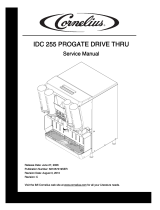
FIGURE 1
Electrical Connections: 6 ft long power cord with 3-prong plug attached to dispenser.
Power Requirements: 9.3 amps at 120 volts dedicated power supply.
Water Supply Requirements: 100 psi (7 bar) maximum static pressure 40 psi (28 bar) minimum
dynamic pressure. 3/8” minimum water line recommended.
CO2 Requirements: 100 psi max to unit regulated to 35 psi (2.4 bar) to Progate 2 ice gate system, 75
psi (5.2 bar) carbonator.
Progate 2 Features
Progate Portion Ice Control Features
• 4 Programmable ice dispense sizes
• Automatic/Manual Ice Dispense Modes
• Unit Power On/Off Switch
• Programmable Agitation Time
Lid Dispenser
• 4 lid dispenser locations on the unit
• 3 Separate removable lid dispensers for small/medium, large, and extra large lids
Straw Holder
• Holds up to 140 regular sleeved straws
20.756
39.750
36.901
30.000
PCX
OUT OF RATIO
LABEL
CORNELIUS
LOGO
UNIT
SERIAL NUMBER

IDC 255 Progate Drive Thru Installation Manual
Publication Number: 621057419INS - 4 - © 2006, IMI Cornelius Inc.
INSTALLATION
MOUNTING AND PLACEMENT
IMPORTANT: TO THE INSTALLER.
It is the responsibility of the Installer to ensure that the water supply to the dispensing equipment
is provided with protection against backflow by an air gap as defined in ANSI/ASME A112. 1.2–
1979; or an approved vacuum breaker or other such method as proved effective by test.
Water pipe connections and fixtures directly connected to a potable water supply shall be sized, installed,
and maintained according to Federal, State, and Local laws.
1. Locate the dispenser indoors on a level counter top.
A. LEG OPTION
Unpack the four (4) legs and install them into the threaded holes provided in the bottom of the
unit. The installer must provide flexibility in the product and utility supply to permit shifting the
position of the dispenser sufficiently to clean the area beneath it.
COUNTER MOUNTING
The ice drink dispenser must be sealed to the counter. The template drawing indicates where openings
can be cut in the counter. Locate the desired position for the dispenser, then mark the outline dimensions
on the counter using the template drawings. Cut openings in counter.
FIGURE 2
30
26 3/81 13/16
15/16
18 5/8
12
9
31/2
91/2
11
23
21 1/4
30
31 1/2
REMOVA BLE SINK
RECOMMENDED COUNTER OPENING SIZE
9 X 12 FOR UTILITIES AND BEVERAGE
TUBING. OPENING CAN BE L OCATED
ANYWHERE WITHIN SHADED AREA .
7/16 DIA.
23 1/16
ZStyle

IDC 255 Progate Drive Thru Installation Manual
© 2006, IMI Cornelius Inc. - 5 - Publication Number: 621057419INS
Apply a continuous bead of NSF International (NSF) silastic sealant (Dow 732 or equal) approximately
1/4-inch inside of the unit outline dimensions and around all openings. Then, position the unit on the
counter within the outline dimensions. All excess sealant must be wiped away immediately.
2. The beverage tubes, drain tube and power cord are routed through the large opening in the bottom
of the unit. See the MOUNTING TEMPLATE for locating the required clearance opening in the
counter for these utility lines.
DRIP TRAY DRAIN ASSEMBLY: Route the drain tube to an open drain with the end of the tube above
the “flood” level of the drain. Use the tubing, fittings, clamps, and insulation provided with the Dispenser
to assemble the drain. The completed drain line must pitch continuously downward and contain no
“traps” or improper drainage will result.
FIGURE 3
NOTE: IMI Cornelius Inc. recommends that a water shutoff valve and water filter be installed in
the plain water inlet supply line. A Cornelius Water Filter (P/N 313860000) and QUICK
DISCONNECT SET (P/N 313867000) are recommended.
CAUTION: Check the minimum flow rate and the maximum pressure of the plain water inlet supply
line. MINIMUM FLOW RATE MUST BE AT LEAST 125-GALLONS PER HOUR. If flow rate is less
than 125-gallons per hour, starving of the carbonator water pump will occur. Starving will overheat
the carbonator’s water pump, causing the safety thermostat on the pump outlet to stop the water
pump motor. Overheating could occur if the plain water supply line flow rate drops below 125-
gallons per hour. INCOMING PLAIN WATER INLET SUPPLY LINE WATER TO PUMP PRESSURE
MUST REMAIN A MINIMUM OF 10 psi BELOW THE CARBONATED CO
2
OPERATING
PRESSURE. (Example: Carbonator CO
2
operating pressure is 75 psi and the maximum water
pressure can be no more than 65 psi, etc.). Static water pressure higher then the static CO
2
pressure can cause carbonator flooding, malfunction, and leakage through the carbonator relief
valve. If water is exceeding maximum pressure specifications, a Water Pressure Regulator Kit must
be installed in the plain water inlet supply line.
3. Cut power to the carbonator by turning off its power switch, the switch is located on the junction box
of the pump and motor assembly. Locate the carbonator pump assembly and connect to power cord
from the Ice/Drink Unit to the pump. The cord is connected to the unit’s electrical box and has an
electrical connector on the end that plugs into a receptacle in the junction box at the carbonator
pump assembly. Connect inlet water to pump and pump outlet to Ice/Drink Unit using 3/8-inch food-
grade tubing.
DRAIN LINE
1" I.D. PLASTIC TUBING
(6') WITH INSULATION
HOSE CLAMP

IDC 255 Progate Drive Thru Installation Manual
Publication Number: 621057419INS - 6 - © 2006, IMI Cornelius Inc.
4. Connect the beverage system product tubes as indicated in applicable Flow Diagram in this manual
or on the back of the splash panel. This work should be done by a qualified service person.
NOTE: See applicable Flow Diagram or Decal on the lower front of the unit for the location of
syrup and water connections.
5. Clean the hopper interior.
6. Connect the unit power cord to a 120 volt, 60 cycle, 3–wire grounded receptacle. For 220-240 Volt
International Units, a 3-wire power cord is provided. An adapter plug for the particular country will
need to be provided by the Installer.
ADJUST CARBONATOR CO
2
REGULATOR AND TURN WATER INLET SUPPLY
L
INE ON
1. Open (counterclockwise) CO
2
cylinder valve slightly to allow lines to slowly fill with gas, then open
the valve fully to back-seat the valve. (Back-seating the valve prevents leakage around the valve
shaft).
2. The carbonator CO
2
regulator is fixed at a nominal 75 psi.
3. Open one of the post-mix dispensing valves to exhaust trapped air inside the carbonator tank.
4. Open the water inlet supply line shutoff valve.

IDC 255 Progate Drive Thru Installation Manual
© 2006, IMI Cornelius Inc. - 7 - Publication Number: 621057419INS
CO2 INSTALLATION
WARNING: Machine is designed to work only with CO2. Store air supplied from a compressed air system
could contain moisture and oils that could damage and/or cause the Ice Gate to loose performance or
malfunction.
1. Use 1/4” tubing capable of handling a minimum of 120 psi.
2. Guide CO2 lines from back of machine to front.
3. Locate CO2 line and connect to the barb fitting.
4. Use Oetiker clamps to secure all lines to barbed fittings.
5. Replace lower splash panel to frame.
FIGURE 4
POWER INSTALLATION
The machine is equipped with a 3 Prong plug (hot, neutral, ground) and is plugged into any standard wall
outlet capable of handling 9.3 amps at 120 volts. Cord may be wrapped and stored under machine for
shipment.
PROGATE CO SHUTOFF
2
CARBONATOR FEED
CO INPUT
2

IDC 255 Progate Drive Thru Installation Manual
Publication Number: 621057419INS - 8 - © 2006, IMI Cornelius Inc.
WATER INSTALLATION
To access cold plate water inlets
1. Remove screws holding attaching lower splash panel to frame and slide panel away from machine.
2. Use Oetker clamps to secure lines to barbed fittings.
FIGURE 5
FIGURE 6
3. Use 3/8” tubing capable of handling a
minimum of 120 psi. Approved for food
applications.
4. Guide water lines from back of machine to
left front and attach to cold plate lines W1
(carbonator water line) and W2 (plain
water or mains water line).
NOTE: W4 is the re-circulation line which is
connected to a remote tower (A&W remote
tower).
5. Turn on pressure and check for leaks.
FIGURE 7
FIGURE 8 [Note: Shown without TotalFlex 1 (TF 1)]
W1
W2
W4
DETAIL A SCALE 1.500
SEE DETAIL A

IDC 255 Progate Drive Thru Installation Manual
© 2006, IMI Cornelius Inc. - 9 - Publication Number: 621057419INS
OPERATION INSTRUCTIONS
LID DISPENSER OPERATION
The lid holder assembly is designed to help with lid storage and dispensing in a crew serve environment.
The holder comes in several sizes to accommodate different size lids.
• Small/Medium holder accommodates both small and medium size lids.
• Large holder accommodates only large lids.
• Extra large holder accommodates only extra large lids.
The lid dispensers are designed to be removed from the front of the merchandiser to make loading the
dispensers simpler and allow for cleaning of the merchandiser and lid dispensers. The dispensers can be
arraigned in any configuration with room for four on the merchandiser face.
UNIT OPERATION
WARNING: The unit must be electrically grounded to avoid possible fatal electrical shock or serious
injury to the operator. The unit power cord is equipped with a three-prong plug. If a three-hole
(grounded) electrical outlet is not available, use an approved method to ground the unit.
CAUTION: Never operate the carbonator pump with the water inlet supply line shutoff valve
closed. “Dry running” the water pump will burn out the pump. A pump damaged in this manner is
not covered by warranty.
1. Connect electrical power to the Unit.
2. Locate the switch on the junction box of the carbonator pump, and turn it ON. The water pump will
start and fill the carbonator tank with carbonated water. The water pump will stop when the
carbonator tank is full.
3. Check for water and CO
2
leaks, and tighten any loose connections
4. Dispense several drinks until the carbonator pump cycles on. The refill time should be about 5-7
seconds.
5. If the carbonator pump appears to be short-cycling, meaning a refill time of 1-2 seconds, refer to the
Troubleshooting section in the back of this manual.

IDC 255 Progate Drive Thru Installation Manual
Publication Number: 621057419INS - 10 - © 2006, IMI Cornelius Inc.
LOADING OF LID DISPENSER
IMPORTANT: To assure best operation lids should be replaced when the last lid is below the
black plastic bottom.
Plastic Wrapped lids
1. To remove grab the lid dispenser lifting and pulling away from merchandiser.
FIGURE 9
FIGURE 10
2. Get fresh sleeve of lids and position so
that lid bottom is up.
3. Remove lid dispenser top if present.
4. Tear open bag.
FIGURE 11
5. Slide sleeve into tube Pull plastic from stack replace top and place lid dispenser back in position on
the merchandiser.
FIGURE 12
FIGURE 13

IDC 255 Progate Drive Thru Installation Manual
© 2006, IMI Cornelius Inc. - 11 - Publication Number: 621057419INS
Individual lids
1. Stack lids on clean flat surface with lid top
facing down.
FIGURE 14
2. Turn dispenser upside down and trap lids
in the tube.
FIGURE 15
3. Place your hand over the top to capture
lids and turn it right side up.
FIGURE 16

IDC 255 Progate Drive Thru Installation Manual
Publication Number: 621057419INS - 12 - © 2006, IMI Cornelius Inc.
LID DISPENSER OPERATION
To dispense a lid:
1. Place hand in finger slot
2. Grab edge of lid and pull.
LID DISPENSER MAINTENANCE
The lid dispensers are manufactured out of materials that can survive chlorine-based cleaners and warm
water <100°F. Ensure that the parts are thoroughly dried before refilling with lids.
NOTE: Lid dispenser parts should not be soaked in the powersoak washing machine as this will
result in the parts getting scratched. Instead the dispenser parts should be rinsed in warm soap
water and then dried.
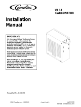
PROGATE 2 CONTROL BOX OPERATION
Portion Control Box Functions
The portion control box on the PROGATE 2 has several functions including dispensing 4 programmed ice
portions for 4 cup sizes, programming and a manual dispense mode.
1. Main Power ON OFF: Turns power to the entire machine off. Lights Orange when ON.
2. Agitator Push ON: Turns on agitator and opens ice gate allowing continuous dispense. This button
will turn green in the manual mode and be off in PROGATE automatic. This button will also agitate
in the automatic mode but not dispense ice.
3. Mode Switch Manual/Progate: Turns on agitator and opens ice gate allowing unlimited ice portion.
4. Program Button: The programming button is used with cup size button enabling the user to enter
the portion programming mode to adjust the ice portions. The programming button is used with the
directional arrow buttons to adjust the agitation time.
5. Ice Portion Dispense Buttons: Used to dispense the appropriate ice portion. Can also be used in
conjunction with the program button to program a portion size.
LID PIVOT POINT
LID SUPPORT
LID
FINGER
GUIDE
POSITION 1
POSITION 2
POSITION 3
BASE
1
2
3
6
5
7
8
4
1. MAIN POWER ON/OFF
2. AGITATOR PUSH ON
3. MODE SWITCH MANUAL/PROGATE
4. PROGRAM BUTTON
5. ICE PORTION DISPENSE BUTTONS
6. ICE PORTION BAR
7. PROGATE ON LIGHT
8. PORTION SIZE UP/DOWN KEYS

IDC 255 Progate Drive Thru Installation Manual
© 2006, IMI Cornelius Inc. - 13 - Publication Number: 621057419INS
6. Ice Size Program Bar: The program bar is only active in the program mode as a visual aid in
setting the portion size.
7. Light: On start up of the unit or during a mode change (Manual to Progate) this light turns orange to
inform the user that the unit is going through a self diagnostic test. On completion of this test the
light turns green to inform the user that the machine is ready to dispense. If the light remains solid
on red and the unit is not dispensing any ice when an ice portion is pressed this should generate a
service call. During ice dispense if there is insufficient ice in the ice chute then the light turns red
instantaneously to inform the user that there is insufficient ice. Once the user releases the portioned
button then the red light goes out.
8. Portion Up/Down Buttons: The program bar is only active in the program mode to change the ice
dispense program size.
Programming (Changing) the Ice Portion
To change the size of any of the four ice dispense sizes follow the steps below.
1. To enter the program mode press the Program Button and Desired Size button at
the same time and hold for 5 seconds.
2. The Ice Portion Bar will come on
3. Press the UP ARROW button to increase the amount of dispensed ice. The LED will move
towards the right indicating the Ice Portion has been increased.
4. Press the DOWN ARROW button to decrease the amount of dispensed ice. The LED will
move towards the left indicating the Ice Portion has been decreased.
5. To exit the program mode press the Desired Size button or wait 10 seconds and the control
will return to the dispense mode.
6. Place a cup under the ice chute and press the just programmed dispense size button If
amount dispense amount is not the desired amount repeat the process.

IDC 255 Progate Drive Thru Installation Manual
Publication Number: 621057419INS - 14 - © 2006, IMI Cornelius Inc.
Agitation Time
The software coding for the progate system involves a direct relationship between the dispense time and
the agitation time.
The relationship is expressed below.
Agitation Time (A
T
) = Dispense Time (D
T
) x Agitation Ratio
2
(R
A
)
Dispense Time (mS) Agitation Ratio Agitation Time (mS)
50 10 500
70 10 700
90 10 900
110 10 1100
130 10 1300
150 10 1500
170 10 1700
190 10 1900
210 10 2100
230 10 2300
Dispense Time (mS) Agitation Ratio Agitation Time (mS)
50 16 800
70 16 1120
90 16 1440
110 16 1760
130 16 2080
150 16 2400
170 16 2720
190 16 3040
210 16 3360
230 16 3680
Dispense Time (mS) Agitation Ratio Agitation Time (mS)
50 28 1400
70 28 1960
90 28 2520
110 28 3080
130 28 3640
150 28 4200
170 28 4760
190 28 5320
210 28 5880
230 28 6440

IDC 255 Progate Drive Thru Installation Manual
© 2006, IMI Cornelius Inc. - 15 - Publication Number: 621057419INS
The agitation time equals the dispense time multiplied by the agitation ratio. The user is given the
flexibility to change the agitation ratio thereby altering the agitation time in order to ensure that the ice
chute is always filled with ice for all the different ice types.
FIGURE 17
Programming (Changing) the Agitation Time
1. Simultaneously Press and hold for 3 seconds, the button and also both direction arrow
buttons to enter the programming mode.
2. The LED meter turns ON once the programming mode is entered. Visual feedback of ratio/agitation
time is obtained from the visual programming LED . The LED meter shows the
existing agitation ratio enabling the user to.
3. Vary the agitation time using the directional arrow buttons. Left to decrease and right direction
arrow button to increase.
2
10 14 16 1812
24
20 22 26 28

IDC 255 Progate Drive Thru Installation Manual
Publication Number: 621057419INS - 16 - © 2006, IMI Cornelius Inc.
Ice Portion Bar
The portion bar is used to determine the amount of time programmed for each size button. Each button
has a minimum and maximum amount of time that can be programmed. If a button cannot be adjusted to
the size desired use another button to get the desired results.
FIGURE 18
=20mS
50mS
230mS
“S” Small
80mS
260mS
“M” Medium
150mS
330mS
“L” Large
230mS
410mS
“XL” XLarge
/