Page is loading ...

IMI CORNELIUS INC.
One Cornelius Place
Anoka, MN 55303–6234
Telephone (800) 238–3600
Facsimile (612) 422–3246
BEVERAGE DISPENSING SUPPORT SYSTEM ASSEMBLY (MODEL NO.
2232MS) INSTALLATION AND SERVICE MANUAL
MANFACTURED
BY
IMI CORNELIUS INC.
ANOKA, MINNESOTA 55303–1592
BEVERAGE CONTROL PANEL ASS’Y
Manual Part No. 0713
June 5, 1991
Revised: April 23, 1992
Control Code A
THIS DOCUMENT CONTAINS IMPORTANT INFORMATION
This Manual must be read and understood before the installation and operation of this Equipment.
IMI Cornelius Inc. 1990–92 Printed in U.S.A.

1 0713
GENERAL DESCRIPTION
Warranty Registration Data
(to be filled out by customer)
Model Number;
Serial Number;
Install Date;
Local Authorized
Service Center;
GENERAL WARRANTY POLICY
IMI Cornelius Inc; warrants that all equipment and
parts are free from defects in material and
workmanship under normal use and service, AS
MORE EXPRESSLY DEFINED AND LIMITED BY
SPECIFIC WARRANTIES COVERING EACH
PRODUCT.
TERMS AND CONDITIONS
PRICES...All prices are F.O.B. factory. Taxes
imposed by any present or future federal, state or
local laws, if paid by us, will be charged to purchaser.
Title and risk of loss to equipment pass to purchaser
upon delivery to carrier.
TERMS...Terms of net thirty (30) days from date of
invoice will be gladly extended to those customers of
known and acceptable financial standing. Otherwise,
orders must be accompanied by cash. A service
charge of 11/2% per month, which is an effective
annual percentage rate of 18%, will be charged for
invoices not paid within thirty days, but in no event
will the monthly service charge exceed 1/12 of the
annual percentage rate allowable under applicable
state laws.
RETURNED GOODS...Merchandise must not be
returned without prior approval or consent, which will
be given or withheld at our sole discretion. (All
returned merchandise must be sent freight
prepaid to IMI Cornelius Inc; Anoka, Minnesota).
If the merchandise is in a new, unused condition and
is in its original carton with all the original packing
and is a configuration appearing in our current
catalog, it will be accepted back (subject to prior
approval as stated above) and a credit allowed
amounting to the original selling price or current
selling price, whichever is lower, less the restocking
charge indicated below.
If returned goods are received by Cornelius: Within
60 days of invoice date –– 10% of applicable sel-
ling price.
Within 61–120 days of invoice date –– 20% of ap-
plicable selling price.
Over 120 days of invoice date –– 30% of applicable
selling price.
Shipments of returned merchandise sent collect will
not be accepted. Used or discontinued equipment
will not be accepted for credit under any
circumstances. Item returned to IMI Cornelius Inc;
for credit or reimbursement, having a value of less
the 25.00 dollars will not receive credit.
CLAIMS...In the event of shortage, notify carrier as
well as us immediately. In the event of damage,
notify carrier. We are not responsible for damage
occurring in transit, but will gladly render assistance
necessary to pursue your claim. Merchandise must
be inspected for concealed damage within 15 days of
receipt.
ORDERING INFORMATION
Please check the part numbers carefully when
ordering. Be sure to include: Quantity, Part. No.
Description, and How to Ship––if you have specific
routing plans.
Note: quantity prices may be available on spare
parts. Save money by ordering larger quantities
or bulk packaging on specific items shipped
from Anoka.
Compare quality, performance and prices. Then
consolidate and simplify your ordering procedure by
ordering current service parts from IMI Cornelius Inc;
located nearest to your area.
To reduce processing and shipping time please
submit separate orders for service parts, rather than
combine orders with equipment.
SHIPPING INFORMATION
Unless otherwise instructed, all merchandise will be
shipped as follows:
0–150 Lbs. (0–68 KG) United Parcel Service
Over 150 Lbs. (68 KG) Truck
Cornelius shall select point of origin for shipments to
give the most efficient service. Freight charges are
from manufacturing point.

16112
COMPLETE SERVICE
Your trained Cornelius Sales Person stands ready to serve you with ordering and technical assistance.
He can also offer you success proven merchandising ideas and placement programs that will help you to
locate Cornelius beverage equipment in retail accounts. Complete repair and installation service by facto-
ry trained personnel is available at Authorized Service Centers. Addresses are available at your request.
Spare parts may also be ordered from our Authorized
Service Centers.
HOME OFFICES AND MANUFACTURING
IMI Cornelius Inc.
One Cornelius Place
Anoka, Minnesota 55303-1592
(612) 421-6120
800-238-3600
FAX (612) 422-3255
Our 800 number access’ the nearest Distribution Center for sales assistance.
DISTRIBUTION CENTERS
NORTHWEST: IMI Cornelius Inc.
One Selina Drive
Albany, New York 12205
(518) 869-6606
FAX 518-869-9038
800-238-3600
SOUTHEAST: IMI Cornelius Inc.
6150-D LaGrange Blvd.
Atlanta, Georgia 30336
(404) 349-0412
FAX 404-346-7054
800-238-3600
SOUTHWEST: IMI Cornelius Inc.
7427 Tower
Ft. Worth, Texas 76118
(817) 654-3888
FAX 817-590-9639
800-238-3600
WEST: IMI Cornelius Inc.
2089 Burroughs Avenue
San Leandro, California 94577
(510) 351-0961
FAX 510-351-2623

3 0713
TABLE 1. SPECIFICATIONS
Model Numbers (Standard Assemblies W/O Optional Kits)
Domestic Units:
Beverage Control Panel (one carbonator) Requiring Connection to one Post-Mix Dispenser 1416
Beverage Control Panel (two carbonator) Requiring Connection to Two Post-Mix Dispenser 0516
Export Units:
Beverage Control Panel (one carbonator) Requiring Connection to One Post-Mix Dispenser 1548
Beverage Control Panel (two carbonator) Requiring Connection to Two Post-Mix Dispenser 0187
Overall Dimension:
Width 50.5 inches (12.827 M)
Height 91 inches (23.114 M)
Depth 19.5 inches (495.3 MM)
Shipping Weights (approximate):
Beverage Control Panel (one carbonator) 363 Pounds (164.7 KG)
Beverage Control Panel (two carbonator) 395 Pounds (179.17 KG)
Water Pressure Requirements (see note) 45 to 75–PSI (3.10 to 5.17 BARS)
Ambient Operating Temperature 40F (4.44C) to 100F (37.8C)
Carbonators Electrical Requirements:
Domestic:
Operating Voltage 115VAC, 60HZ
Current Draw 6.8 Amps
Export:
Operating Voltage 230VAC, 50 HZ
Current Draw 3.3 Amps
Note: If plain water source pressure is above 75–PSI (5.17 Bars), optional Water Pressure Regulator Kit
must be installed and adjusted to 75–PSI (5.17 Bars). If water source pressure is consistently less than
45–PSI (3.10 Bars), the Optional Water Pressure Booster Kit must be installed in the system. The
Booster Kit will boost water pressure from 50 to 70–PSI (3.45 to 4.83 Bars).

4
0713
INSTALLATION
This manual is intended to assist the installer and
service personnel in the installation, operation, and
maintenance procedures to be performed on the
Beverage Control Panel Assembly (see Figure 1 and
applicable Figure 3, 4, 5, or 6).
The Beverage Control Panel Assembly is designed
to filter, pressure regulator, and distribute plain and
carbonated water, CO
2
gas, and syrup to the
Post–Mix Beverage Dispenser or dispensers and
various other equipment connected to the system.
NOTE: The Beverage Control Panel Assembly is
manufactured in America and has American
sizes on the hardware. All metric conversion are
approximate and vary in size.
NOTE: The Beverage Control Panel Assembly
was thoroughly inspected before leaving the
factory and the carrier has accepted and signed
for it. Any damage or irregularities should be
noted at the time of delivery (or not later than 15
days from date of deliver) and immediately
reported to the delivering carrier. Request a
written inspection report from Claims Inspector
to substantiate any necessary claim. File claim
with the delivering carrier, not with IMI Cornelius
Inc.
INSTALLING POST–MIX DISPENSER(S)
Refer to manual(s) provided with the Post–Mix
Dispenser(s) for installation instructions, then install
Dispenser(s) in operating location(s).
INSTALLING BEVERAGE CONTROL
PANEL ASSEMBLY
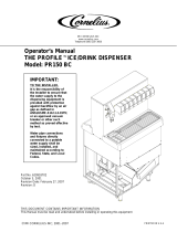
Your Beverage Control Panel Assembly may be
equipped with one or more of the optional kits as
shown in Figure 2. Figure 1 shows the standard
Beverage Control Panel Assembly with no optional
kits and Figure 2 shows the panel assembly with
optional kits installed.
NOTE: A dedicated and properly grounded
electrical outlet with proper electrical
requirements must be located close to the
Beverage Control Panel Assembly installation
location to provide electrical power to
(depending upon Beverage Control Panel Model
Number) one or two carbonators.
If your Beverage Control Panel Assembly is
equipped with either or both the optional air
compressor kit or the water pressure booster kit,
dedicated properly grounded electrical outlets with
proper electrical requirements must also be located
close to the Beverage Control Panel Assembly
installation location to provide electrical power.
No other electrical equipment should be connected to
these electrical circuits. ALL ELECTRICAL WIRING
MUST CONFORM TO NATIONAL AND LOCAL
ELECTRICAL CODES.
Table 2. Loose-Shipped Parts
Item
No. Part No. Name Qty.
1 300894–000 Water Surge Tank 1
2 300893–000 Strap, Surge Tank 1
3 300912 Tube Ass’y, .375 I.D.
By 56–in long
1
4 311304 Tapered Gasket,
Black
4
5 0590 Elbow Ass’y, Surge
Tank
1
INSTALLING WATER SURGE TANK (ITEM 1)
ON BEVERAGE CONTROL PANEL
ASSEMBLY
NOTE: It is suggested for ease of assembly, that
the loose–shipped WATER SURGE TANK (item 1)
be installed on the Beverage Control Panel
Assembly upper frame before the Panel
Assembly is set upright and fastened to the wall.
1. Install ELBOW ASS’Y SURGE TANK (item 5) in
top of WATER SURGE TANK (item 1) as shown
in Figure 17. Seal pipe thread connection with
pipe sealing compound.
2. Refer to applicable Figure 1 or 2 for water surge
tank location on Beverage Control Panel
Assembly upper frame, then remove two
self–drilling screws from frame.
3. Position water surge tank in position on
Beverage Control Panel Assembly.
4. Place STRAP, SURGE TANK (item 2) in
position around water surge tank and align
holes in strap with holes in frame where two
self–drilling screws were removed.
5. Secure strap to frame with two self–drilling
screws removed in step 2) preceding.

5
0713
6. Connect one end of TUBE ASS’Y (item 33) to
water surge tank elbow assembly 3/8–inch flare
(5/8–18) fitting as shown in applicable Figure 3,
4, 5, or 6. Seal connection with TAPERED
GASKET, BLACK (item 4).
7. Connect other end of tube assembly to water
manifold assembly 3/8–inch flare (5/8–18) fitting
on water filter assembly (see applicable Figure
3, 4, 5, or 6). Seal connection with TAPERED
GASKET, BLACK (item 4).
FASTENING BEVERAGE CONTROL
PANEL ASSEMBLY TO WALL
WARNING: The Beverage Control
Panel Assembly must be securely
fastened to the wall before
connecting the assembly into the system.
The Beverage Control Panel Assembly must
be fastened to the wall with six fasteners
provided by the Installer) and each fastener
must be capable of resisting a 200 pound
(90.7 KG) pull. Be very careful when handling
the assembly as it is very top heavy and
could fall and cause serious personal injury
and also equipment damage.
Refer to instructions in previous WARNING note and
secure Beverage Control Panel Assembly to wall as
follows:
1. Very carefully, lay panel assembly upper frame
over on its back side. Slide telescoping lower
frame up on panel assembly upper frame.
2. Very carefully, lift Beverage Control Panel
Assembly up and place in position up against
wall.
3. Using screw adjusters on bottoms of Legs,
adjust until Control Panel Assembly sits level.
4. Secure Control Panel Assembly to wall with six
fasteners provided by the installer.
5. Using .156 I.D. tubing provided in installation kit,
connect one end of tubing to vented double
check valve (see applicable Figure 3, 4, 5, or 6),
then route other end of tubing to a permanent
floor drain.
6. Fasten tubing to frame assembly with wire ties
provided in installation kit.
CONNECTING SUGAR–BASE SYRUP TANKS
CO
2
LINES TO BEVERAGE CONTROL
PANEL ASSEMBLY CO
2
MANIFOLD
(see Figure 7)
1. Using .265 I.D. tubing, fittings, gas quick
disconnects, and tubing clamps, provided in the
installation kit, make up three gas lines to be
connected between the CO
2
manifold and the
sugar–base syrup tanks.
2. Connect three gas lines swivel nut ends to CO
2
check valves on Beverage Control Panel
Assembly CO
2
manifold. Seal connections with
white tapered gaskets.
CONNECTING DIET SYRUP TANK CO
2
LINE
TO BEVERAGE CONTROL PANEL
ASSEMBLY DIET SYRUP CO
2
REGULATOR.
(see Figure 7)
3. Using .265 I.D. tubing, fittings, gas quick
disconnect, and tubing clamps, make up one
gas line to be connected between the Beverage
Control Panel Assembly diet–syrup tank.
4. Connect swivel nut end of gas line to check
valve on outlet of the diet–syrup tank CO
2
regulator. Seal connection with white tapered
gasket.
CONNECTING BEVERAGE CONTROL
PANEL ASSEMBLY TO POST–MIX
DISPENSER(S) AND OTHER EQUIPMENT TO
BE CONNECTED TO THE SYSTEM
(see Figure 7)
NOTE: The syrup, plain and carbonated water
and CO
2
lines to the Post–Mix Dispenser(s) and
various other equipment at the installation site
may be routed overhead or through a floor chase
from the Beverage Control Panel Assembly.
MAKE SURE ALL LINES ARE LABELED FOR
IDENTIFICATION.
Refer to manual(s) provided with the Post–Mix
Dispenser(s) to connect plain water, carbonated
water, and syrup lines to the Dispenser(s).
Center–Island Installation with Optional Syrup Tanks
Hookup (see Figure NO TAG)
Connect CO
2
, plain water, carbonated water, and
syrup lines between Beverage Control Panel
Assembly, the Post–Mix Dispenser, and other
equipment to be connected to the system. Optional
syrup tanks Kit (P/N 0673) is used to connect four
syrup tanks into system.
Connect insulated plain water line between plain
water line connected to Post–Mix Dispenser cold
plate and the Orange Juice Dispenser.

6
0713
Center–Island and Second Dispenser Installation
with Optional Syrup Tanks Hookup (see Figure
NO TAG)
Connect CO
2
, plain water, carbonated water, and
syrup lines between Beverage Control Panel
Assembly, the Post–Mix Dispensers, and other
equipment to be connected to the system. Optional
Syrup Tanks Kit (P/N 0673) is used to connect four
syrup tanks into the system.
Connect insulated plain water line between plain
water line connected to Post–Mix Dispenser cold
plate and the Orange Juice Dispenser.
Center–Island Installation with Bulk Syrup Tank
Hookup (see Figure NO TAG).
Connect CO
2
, plain water, carbonated water, and
syrup lines between Beverage Control Panel
Assembly, the Post–Mix Dispenser, and other
equipment to be connected to the system.
Connect insulated plain water line between plain
water line connected to Post–Mix Dispenser cold
plate and the Orange Juice Dispenser.
Center–Island and Second Dispenser Installation
with Bulk Syrup Tank Hookup (see Figure NO TAG).
Connect CO
2
, plain water, carbonated water and
syrup lines between Beverage Control Panel
Assembly, the Post–Mix Dispensers, and other
equipment to be connected to the system.
Connect insulated plain water line between plain
water line connected to Post–Mix Dispenser cold
plate and the Orange Juice Dispenser.
PREPARATION FOR OPERATION
BEVERAGE CONTROL PANEL ASSEMBLY
NOTE: The Beverage Control Panel Assembly
must be connected to a water source with water
pressure between 45 and 75–PSI (3.10 and 5.17
Bars). If water pressure is over 75–PSI (5.17
Bars), an Optional Water Pressure Regulator Kit
(P/N 300919–00) must be installed. If plain water
source is below 45–PSI (3.10 Bars), an Optional
Water Pressure Booster Kit must be installed in
the system to boost water pressure to 75–PSI
(5.17 Bars).
IMPORTANT: DO NOT operate (if applicable) the
Optional Water Pressure Booster water pump
with no water connected to the Beverage Control
Panel Assembly. Operating water pump dry will
void its factory warranty.
1. Install loose–shipped water filter cartridges on
water filter assembly.
2. Make sure all shutoff valves on water manifold
assembly and water filter assembly are in
‘‘OFF’’ position.
IMPORTANT: DO NOT operate carbonator(s)
water pump(s) or water pressure booster system
(if applicable) water pump with no water in the
system. Operating pumps dry will cause damage
to the pumps which will void their factory
warranty.
3. Connect plain water source line, meeting
requirements of preceding NOTE, to Beverage
Control Panel Assembly.
4. Open Beverage Control Panel Assembly plain
water source shutoff valve.
5. Beverage Control Panel Assembly equipped
with Everpure water filters (see applicable
Figure 3 or 5).
A. Connect length of garden hose to FILTER
‘‘ACTIVATION VALVE,’’ then route hose to
a permanent drain.
B. Open ‘‘ACTIVATION VALVE’’ and allow
approximately 28–gallons of water to flow
through the water filters, then close valve.
6. Standard Installation (see Figure 7).
WARNING: CO
2
Displaces Oxygen.
Strict Attention must be observed in
the prevention of CO
2
(carbon
dioxide) gas leaks in the entire CO
2
and soft
drink system. If a CO
2
gas leak is suspected,
particularly in a small area, immediately
ventilate the contaminated area before
attempting to repair the leak. Personnel
exposed to high concentration of CO
2
gas
will experience tremors which are followed
rapidly by loss of consciousness and
suffocation.
Connect bulk CO
2
tank CO
2
supply line to barbed
fitting on CO
2
manifold. Secure connection with
tubing clamp.
Installation employing the optional high–pressure
CO
2
Regulator Assembly Kit (P/N 0708) (see Figure
7)
WARNING: To avoid personal injury
and/or property damage, always
secure CO
2
cylinders with safety
chain to prevent them from falling over.
Should the valve become accidentally
damaged of broken off, CO
2
cylinder can
cause serious personal injury.

7
0713
A. Locate two full CO
2
cylinders in upright
positions next to the CO
2
mounting
bracket. Fasten CO
2
cylinders with safety
chain.
B. Connect two CO
2
lines from Beverage
Control Panel Assembly two primary CO
2
regulators to the CO
2
cylinders.
7. Installation employing the Optional Water
PressureBooster System Kit (see applicable
Figure 3, 4, 5, or 6)
Note service valve on bottom of the Water Pressure
Booster System Water Tank. The water tank must be
pressurized with 40 5–PSI (2.76 .34 Bars) of
commercially dry air, CO
2
, or nitrogen gas through
the water tank service valve before putting system
into operation.
8. Water Surge Tank (see applicable Figure 3, 4,
5,, or 6)
Note service valve on bottom of the water surge
tank. The water surge tank must be pressurized with
12 2–PSI (.83 .14 Bars) of commercially dry air,
CO
2
, or nitrogen gas through the water tank service
valve before putting system into operation.
9. System Connected to Bulk CO
2
Supply (see
Figure 7)
A. Open shutoff valve on bulk CO
2
tank.
B. Adjust CO
2
regulator on bulk CO
2
tank to
105–PSI (7.24 Bars). Pull up on
carbonators tanks relief valves for
approximately two seconds to bleed air
from tanks.
C. Adjust sugar–base syrup tanks CO
2
regulator with 100–PSI (6.9 Bars) gauge on
secondary CO
2
regulator assembly to
60–PSI (4.14 Bars).
D. Adjust diet syrup tank CO
2
regulator with
30–PSI (2.07 Bars) gauge on secondary
CO
2
regulator Assembly to 12–PSI (.83
Bars).
10. System connected to two fifty pound CO
2
cylinders (see Figure 7).
A. Open CO
2
cylinders valves slightly to allow
lines to slowly fill with gas, then open
valves fully to back seat valve.
Back–seating valve prevents leakage
around valve shaft.
B. Adjust two Primary CO
2
regulators to
105–PSI (7.24 Bars). Pull up on
carbonator(s) tank(s) relief valve(s) for
approximately two seconds to bleed air
from tanks.
C. Adjust secondary CO
2
regulator assembly
CO
2
regulator with 100–PSI (6.9 Bars)
gauge for sugar–base syrup tanks to
60–PSI (4.14 Bars).
D. Adjust diet syrup tank CO
2
regulator with
30–PSI (2.07 Bars) gauge on secondary
CO
2
regulator assembly to 12–PSI (.83
Bars).
11. The Post–Mix Dispenser(s) and entire syrup
systems should be sanitized as instructed in
manual(s) provided with Dispenser(s) before
syrup is connected into the systems.
IMPORTANT: Even though sanitizing procedure
has been performed on syrup systems during
initial installation a temporary new tubing plastic
off–taste of dispensed product may occur. If this
off–taste should occur, prepare a solution of
citric acid in proportion as instructed on the
citric acid packaging. Pump citric acid solution
through the syrup systems and all carbonated
and plain water tubes installed as part of the
system. Thoroughly flush syrup systems and all
carbonated and plain water tubes with plain
water to make sure all citric acid has been
removed.
12. Open all plain water shutoff valves on Beverage
Control Panel Assembly.
13. Check entire system for syrup, CO
2
gas, and
plain and carbonated water leaks. Repair if
leaks are evident.
14. Plug carbonator(s) and Water Pressure Booster
system (if applicable) power cords into electrical
outlets.
15. If Optional Air Compressor Kit is being used and
it is desired to operate with compressed air
rather than CO
2
gas pressure.
A. Plug air compressor power cord into
electrical outlet.
B. Place CO
2
/air switchover valve (see Figure
7) in air position.
16. Refer to manual(s) provided with the
Dispenser(s) to put Dispenser(s) into operation.
Operate all dispensing valves to bleed all air
from plain and carbonated water systems.
17. Standard Installation Connected to Bulk Syrup
Tanks (see Figure 7)

8
0713
A. Connect bulk syrup tank into system.
B. Connect three other flavors syrup tanks
into syrup systems.
18. Installation Using Optional Syrup Tank Kit
(P/N 0673) (see Figure 7.)
A. Connect four syrup tanks into syrup
systems.
B. Connect three other flavors syrup tanks
into syrup systems.
19. Operate all Dispenser(s) dispensing valves to
bleed all air from syrup systems.
CHECKING ENTIRE SYSTEM FOR
SYRUP, CO
2
GAS, AND PLAIN AND
CARBONATED WATER LEAKS
Check entire system for syrup, CO
2
gas, and plain
and carbonated water leaks and repair if evident.
SEALING ENDS OF FLOOR CHASE (IF
APPLICABLE)
1. Pack ends of floor chase with paper to within
approximately six–inches from the top.
2. Seal ends of floor chase with plaster of paris
which may be purchased at a local building
materials store.

07139
*BEVERAGE CONTROL PANEL MODEL 0817
AND 0516 ARE EQUIPPED WITH TWO CAR-
BONATOR ASSEMBLIES. MODEL 1416 AND
1548 ARE EQUIPPED WITH ONE CARBONA-
TOR ASSEMBLY.
SECONDARY CO
2
REGULATOR PANEL ASS’Y
CO
2
SWITCHOVER
VALVE
WATER SYSTEM
SURGE TANK
CARBONATOR
ASS’Y(2)
PLUG
FIGURE 1. STANDARD BEVERAGE CONTROL PANEL ASS’Y

10 0713
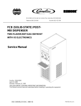
OPTIONAL WATER
PRESSURE BOOSTER
KIT
PRESSURE SWITCH
WATER PRESSURE
BOOSTER SYSTEM
WATER TANK
WATER
SURGE TANK
OPTIONAL PRIMARY
CO
2
REGULATOR
ASS’Y KIT
OPTIONAL AIR
COMPRESSOR KIT
OPTIONAL SYRUP
TANKS KIT
OPTIONAL WATER
PRESSURE
REGULATOR KIT
FIGURE 2. BEVERAGE CONTROL PANEL ASSEMBLY
(WITH ALL OPTIONAL KITS INSTALLED)

071311
OPTIONAL WATER
PRESSURE BOOSTER KIT
SHUTOFF
VALVE
WATER
TANK
PRESSURE
SWITCH
CHECK
VALVE
WATER PUMP
(90–GPH) (341–LPH)
SERVICE
VALVE
WATER
SURGE TANK
SERVICE
VALVE
TO POST–MIX
DISPENSER
CARBONATED
WATER TANK
WATER PUMP
CARBONATOR
WATER PRESSURE
REGULATOR
(12–PSI) (.8–BARS)
FILET BUN
STEAMER
TO POST–MIX
DISPENSER
DOUBLE VENTED
CHECK VALVE(2)
CAPPED
WATER PRESSURE
GAUGE
SHUTOFF
VALVE(7)
STANDARD
TUBE ASS’Y
(SEE NOTE)
WATER
PRESSURE
GAUGE
COFFEE
MACHINE/SEASONAL
DRINKS
WATER PRESSURE
REGULATOR OPTIONAL
WATER SHUTOFF
VALVE
PLAIN WATER
SOURCE
(45 TO 75– PSI)
(3.1 TO 5.1 –BARS)
ICE
MACHINE
PHOSPHATE
FEEDER (F3)
PRE
FILTER
(F1)
FINE FILTERS
(TASTE AND ODOR)
(F2)
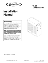
NOTE: THIS TUBE ASS’Y IS
CONNECTED WHEN OPTIONAL
WATER PRESSURE BOOSTER
KIT IS NOT USED.
LINE LEGEND
PLAIN WATER
CARBONATED WATER
FILTER
ACTIVATION
VALVE
FIGURE 3. PLAIN AND CARBONATED WATER SYSTEMS FLOW DIAGRAM
W/EVERPURE WATER FILTERS (MODELS 1416 AND 1548)

12 0713
OPTIONAL WATER
PRESSURE BOOSTER KIT
SHUTOFF
VALVE
WATER
TANK
PRESSURE
SWITCH
CHECK
VALVE
WATER PUMP
(90–GPH) (341–LPH)
SERVICE
VALVE
WATER
SURGE TANK
SERVICE
VALVE
TO POST–MIX
DISPENSER
CARBONATED
WATER TANK
WATER PUMP
CARBONATOR
WATER PRES-
SURE
REGULATOR
(12–PSI)
(.8–BARS)
FILET BUN
STEAMER
TO POST–MIX
DISPENSER
DOUBLE VENTED
CHECK VALVE(2)
CAPPED
WATER PRESSURE
GAUGE
SHUTOFF
VALVE(7)
STANDARD
TUBE ASS’Y
(SEE NOTE)
WATER
PRESSURE
GAUGE
COFFEE
MACHINE/SEASONAL
DRINKS
WATER PRESSURE
REGULATOR OPTIONAL
WATER SHUTOFF
VALVE
PLAIN WATER
SOURCE
(45 TO 75– PSI)
(3.1 TO 5.1 –BARS)
ICE
MACHINE
PRE
FILTER
(F1)
NOTE: THIS TUBE ASS’Y IS
CONNECTED WHEN OPTIONAL
WATER PRESSURE BOOSTER
KIT IS NOT USED.
LINE LEGEND
PLAIN WATER
CARBONATED WATER
FINE
FILTER
TASTE/ODOR
FILTER
ICE MAKER
FEEDER FILTER
FIGURE 4. PLAIN AND CARBONATED WATER SYSTEMS FLOW DIAGRAM
W/CUNO WATER FILTERS (MODELS 1416 AND 1548)

071313
OPTIONAL WATER
PRESSURE BOOSTER KIT
SHUTOFF
VALVE
WATER
TANK
PRESSURE
SWITCH
CHECK
VALVE
WATER PUMP
(90–GPH) (341–LPH)
SERVICE
VALVE
WATER
SURGE TANK
SERVICE
VALVE
TO POST–MIX
DISPENSER
CARBONATED
WATER TANK
WATER PUMP
WATER PRESSURE
REGULATOR
(12–PSI) (.8–BARS)
FILET BUN
STEAMER
TO POST–MIX
DISPENSER
DOUBLE VENTED
CHECK VALVE(2)
WATER PRESSURE
GAUGE
SHUTOFF
VALVE(7)
STANDARD
TUBE ASS’Y
(SEE NOTE)
WATER
PRESSURE
GAUGE
COFFEE
MACHINE/SEASONAL
DRINKS
WATER PRESSURE
REGULATOR OPTIONAL
WATER SHUTOFF
VALVE
PLAIN WATER
SOURCE
(45 TO 75– PSI)
(3.1 TO 5.1 –BARS)
ICE
MACHINE
PHOSPHATE
FEEDER (F3)
PRE
FILTER
(F1)
FINE FILTERS
(TASTE AND ODOR)
(F2)
NOTE: THIS TUBE ASS’Y IS
CONNECTED WHEN OPTIONAL
WATER PRESSURE BOOSTER
KIT IS NOT USED.
LINE LEGEND
PLAIN WATER
CARBONATED WATER
CARBONATOR
CARBONATOR
FILTER
ACTIVATION
VALVE
FIGURE 5. PLAIN AND CARBONATED WATER SYSTEMS FLOW DIAGRAM
W/EVERPURE WATER FILTERS (MODELS 0187 AND 0516)

14 0713
OPTIONAL WATER
PRESSURE BOOSTER KIT
SHUTOFF
VALVE
WATER
TANK
PRESSURE
SWITCH
CHECK
VALVE
WATER PUMP
(90–GPH) (341–LPH)
SERVICE
VALVE
WATER
SURGE TANK
SERVICE
VALVE
TO POST–MIX
DISPENSER
CARBONATED
WATER TANK
WATER PUMP
WATER PRESSURE
REGULATOR
(12–PSI) (.8–BARS)
FILET BUN
STEAMER
TO POST–MIX
DISPENSER
DOUBLE VENTED
CHECK VALVE(2)
WATER PRESSURE
GAUGE
SHUTOFF
VALVE(7)
STANDARD
TUBE ASS’Y
(SEE NOTE)
WATER
PRESSURE
GAUGE
COFFEE
MACHINE/SEASONAL
DRINKS
WATER PRESSURE
REGULATOR OPTIONAL
WATER SHUTOFF
VALVE
PLAIN WATER SOURCE
(45 TO 75– PSI)
(3.1 TO 5.1 –BARS)
ICE
MACHINE
PRE
FILTER
(F1)
NOTE: THIS TUBE ASS’Y IS
CONNECTED WHEN OPTIONAL
WATER PRESSURE BOOSTER
KIT IS NOT USED.
LINE LEGEND
PLAIN WATER
CARBONATED WATER
FINE
FILTER
TASTE/ODOR
FILTER
ICE MAKER
FEEDER FILTER
CARBONATOR
CARBONATOR
FIGURE 6. PLAIN AND CARBONATED WATER SYSTEMS FLOW DIAGRAM
W/CUNO WATER FILTERS (MODELS 0187 AND 0516)

071315
AIR COMPRESSOR KIT (OPTIONAL)
CO
2
/AIR CHANGEOVER
VALVE
SUGAR BASED SYRUP
(60–PSI) (4.14 BARS)
DIET SYRUP
(12–PSI) (.83 BARS
CO
2
CHECK VALVE
SYRUP TANK KIT (OPTIONAL)
CONNECT
TO
DISPENSING
STATIONS
FROM BULK
SYRUP TANK
(STANDARD
INSTALLATION)
ORANGE
SPRITE
DIET
TO CO
2
CYLINDER
CO
2
/AIR CHANGEOVER
VALVE
CONNECT TO CARBONATORS
CO
2
REGULATOR ASS’Y
KIT (OPTIONAL)
SHAKE
MACHINE
BULK CO
2
TANK CONNECTION
(STANDARD INSTALLATION)
CO
2
/AIR CHANGEOVER
VALVE
AIR PRESSURE
REGULATOR
AND COURSE
FILTER
FINE FILTER
TO
DISPENSERS
*THE STANDARD INSTALLATION EMPLOYS
THE USE OF A BULK SYRUP TANK WHICH
IS CONNECTED TO FOUR OF THE DISPENSERS
SYRUP INLET LINES. OPTIONAL SYRUP TANKS
KIT PROVIDES THE MEANS TO CONNECT FOUR
SYRUP TANKS INSTEAD OF THE BULK SYRUP
TANK.
LINE LEGEND
CO
2
/AIR
SYRUP
CONDENSATION
TANK
CONDENSATION
DRAIN TUBE
FIGURE 7. CO
2
/AIR AND SYRUP SYSTEMS FLOW DIAGRAM

16
0713
FIGURE 8. CONNECTION DIAGRAM
(
CENTER–ISLAND INSTALLATION WITH OPTIONAL SYRUP TANKS HOOKUP
)
1
2
3
4
5
6
7
8
9
10
11
12
13
14
15
16
17
SPRITE
DIET
ORANGE
COKE
COKE
COKE
COKE
COKE
BULK
TANK

17
0713
CONN
NBR Part No. DESCRIPTION QTY.
1
770409000 3/8 Swivel - 3/8 Barb Elbow 1
311304000 Gasket 1
309852000 170 Oeitker Clamp 2
2
770695000 1/2 x 3/8 x 3/8 Barb Tee 1
309852000 170 Oeitker Clamp 4
319681000 210 Oeitker Clamp 2
3
176206000 1/2 Nut 1
176205000 1/2 x 3/8 Stem 1
311304000 Gasket 1
309852000 170 Oeitker Clamp 4
4
770105000 1/4 Swivel Hose Stem 1
770101000 1/4 Swivel Nut 1
111353000 145 Oeitker Clamp 2
178025100 Gasket 1
5
770304000 1/4 x 3/8 Swivel Hose Stem 1
770301000 3/8 Swivel Nut 1
311304000 Gasket 1
111353000 145 Oeitker Clamp 2
6
770699000 1/2 x 1/2 x 3/8 Barb Tee 2
770423000 1/2 x 3/8 Barb Splice 1
319681000 210 Oeitker Clamp 10
309852000 170 Oeitker Clamp 6
7
770407000 3/8 x 1/4 Barb Splice 1
309852000 170 Oeitker Clamp 4
111353000 145 Oeitker Clamp 2
8
770607000 3/8 x 3/8 1/4 Barb Tee 1
309852000 170 Oeitker Clamp 4
111353000 145 Oeitker Clamp 2
CONN
NBR Part No. DESCRIPTION QTY.
9
770403000 3/8 x 3/8 Barb Splice 1
309852000 170 Oeitker Clamp 4
10
770621000 3/8 x 1/4 x 1/4 Barb Tee 1
309852000 170 Oeitker Clamp 2
111353000 145 Oeitker Clamp 4
11 Installer Supplied 1
12
770305000 3/8 Swivel Hose Barb 1
770301000 3/8 Swivel Nut 1
309852000 170 Oeitker Clamp 2
311304000 Gasket 1
13
274244000 Gas QD Slot !/4 Barb 1
111353000 145 Oeitker Clamp 2
14
274212000 Syrup QD 1/4 Flare 1
770465000 1/4 Flare x 3/8 Barb 1
309852000 170 Oeitker Clamp 2
15
770402000 1/4 x 1/4 Barb Splice 1
111353000 145 Oeitker Clamp 4
16 Installer Supplied
17
274212000 Syrup QD 1/4 Flare 1
770465000 1/4 FFL x 3/8 Barb 1
309852000 170 Oeitker Clamp 2
311035000 Strainer 1
770750010 1/4 MFL to 1/4 MPT 2
310822000 1/4 FFL to 1/4 FFl 1
178025100 Gasket 2

18
partnum
FIGURE 9. CONNECTION DIAGRAM (CENTER–ISLAND AND SECOND DISPENSER
WITH OPTIONAL SYRUP TANKS HOOKUP
1
2
3
4
5
6
7
8
9
10
11
12
13
14
15
16
17
18
19
coke
coke
coke
orange
diet
sprite
1
6
SPRITE
DIET
ORANGE
COKE
COKE
COKE
COKE
COKE
COKE
BULK
TANK

19
0713
CONN
NBR Part No. DESCRIPTION QTY.
1
770409000 3/8 Swivel -///8 Barb Elbow 1
311304000 Gasket 1
309852000 170 Oeitker Clamp 2
2
770695000 1/2 x 3/8 x 3/8 Barb Tee 1
309852000 170 Oeitker Clamp 4
319681000 210 Oeitker Clamp 2
3
176206000 1/2 Swivel Nut 1
176205000 Swivel Barb 1
311304000 Gasket 1
309852000 170 Oeitker Clamp 2
4
770104000 1/4 Swivel Hose Stem 1
176017000 1/4 Swivel Nut 1
111353000 145 Oeitker Clamp 2
178025100 Gasket 1
5
176271000 1/4 x 3/8 Swivel Hose Stem 1
311242000 3/8 Swivel Nut 1
311304000 Gasket 1
111353000 145 Oeitker Clamp 2
6
770699000 1/2 x 1/2 x 3/8 Barb Tee 2
770423000 1/2 x 3/8 Barb Splice 1
319681000 210 Oeitker Clamp 10
309852000 170 Oeitker Clamp 6
7
770407000 3/8 x 1/4 Barb Splice 1
309852000 170 Oeitker Clamp 4
111353000 145 Oeitker Clamp 2
8
770607000 3/8 x 3/8 x 1/4 Barb Tee 1
309852000 170 Oeitker Clamp 4
111353000 145 Oeitker Clamp 2
CONN
NBR Part No. DESCRIPTION QTY.
9
770403000 3/8 x 3/8 Barb Splice 1
309852000 170 Oeitker Clamp 4
10
770621000 3/8 x 1/4 x 1/4 Barb Tee 1
309852000 170 Oeitker Clamp 2
111353000 145 Oeitker Clamp 4
11 Installer Supplied 1
12
176025000 3/8 Swivel Hose Barb 1
311242000 3/8 Swivel Nut 1
309852000 170 Oeitker Clamp 2
311304000 Gasket 1
13
274244000 Gas QD Slot 1/4 Barb 1
111353000 145 Oeitker Clamp 2
14
274212000 Syrup QD 1/4 Flare 1
770465000 1/4 Flare x 3/8 Barb 1
309852000 170 Oeitker Clamp 2
15
770699000 1/2 x 1/2 x 3/8 Barb Tee 1
770423000 1/2 x 3/8 Barb Splice 1
309852000 170 Oeitker Clamp 4
319681000 210 Oeitker Clamp 6
16
770402000 1/4 x 1/4 Barb Splice 1
111353000 145 Oeitker Clamp 4
17 Installer Supplied
18
274212000 Syrup QD 1/4 Flare 1
770465000 1/4 FFL x 3/8 Barb 1
309852000 170 Oeitker Clamp 2
311035000 Strainer 1
770750010 1/4 MFL to 1/4 MPT 2
310822000 1/4 FFL to 1/4 FFL 1
178025100 Gasket 2
/