Page is loading ...

AKC 55 System Manual RC.IU.B3.22 4-1
Chapter 4 Initial Configuration of an AKC 55
AKC 55 configuration is easy using the keypad and display, and even easier using a
PC with Danfoss AKA 65 Network Interface software connected to the controller.
This chapter describes configuration from the AKC 55 keypad. You can easily adapt
these instructions for the PC keyboard and mouse after reading Chapter 7, “Using
AKA 65 Software on Your PC.”
We will address configuration of each area of a supermarket control system in this
section of the manual. Initial configuration for equipment start-up may be limited to
such items as are necessary to check out the mechanical equipment or provide basic
service. The configuration can be changed or added to at any time later.
Check battery If you did not install the AKC 55, consult Chapter 3-1 and make sure that the battery
enable jumper has been set to the “ON” position; if you do not,your configuration will
be lost whenever power to the controller is interrupted.
Authorization codes When the AKC 55 is turned on for the first time, the Main Menu will appear as at left
below:
Before you can enter configuration information, you must select Authorization and
enter a valid authorization code and account code. Using the right arrow, move the
cursor to Authorization and press ENTER. The Authorization Menu will appear as
at right above, with the cursor in the Auth field.
When you have entered the access code and account number given to you by the
system owner, you will see the words Authorization accepted appear briefly in
reverse video at the very bottom of the screen.
After initial configuration, you will be able to make changes by several different
avenues, which are discussed in Chapter 5, “Using the System.”
Using menus To select from any AKC 55 menu, first use the arrow keys to move the cursor to the
item you want, then press the ENTER key. You can use the EXIT key to retrace

4 - 2 System Manual RC.IU.B3.22 AKC 55
your steps level by level.
Selection of Units
and Language Before using the system, you may wish to change the language used on the screens,
the units used for pressure and temperature, or the date and time format. These
settings will be for the local PC only, and will not affect the display at the AKC 55s in
the system. To change the displayed units, select Store Information from the main
menu and then choose Units/Languages. In the Configuration Units/Languages
screen, select the language you want to see in the controller screens, then select
either psi or bar for pressure; either °F or °C for temperature; and either % or fc
(footcandles) for light level.

AKC 55 System Manual RC.IU.B3.22 4-3
Chapter 4 - 1 Configuring Refrigeration
There are two “routes” you may need to navigate to begin configuring refrigeration.
One begins by selecting Refrigeration from the Main menu, and the other by
selecting Configuration.
Starting with a
Partially Configured
AKC 55 If the AKC 55 you are working with was supplied with a rack, the controller may
have been partially configured by the rack manufacturer. In that case, when you
select Refrigeration from the Main Menu, the AKC 55 will display the Refrigeration
Menu (left). It lists the rack or racks that are partly configured. If you want to
change or add to the configuration of one of these racks, move the cursor to the rack
name and press ENTER. The Rack menu (right) will appear. In this example, only
one rack has been previously configured.
Select Configure Rack and the Configure Rack menu appears.
4 - 4 System Manual RC.IU.B3.22 AKC 55
Now select the type of information you want to supply. We’ll cover a typical cat-
egory right after we talk briefly about the other “route” configuration may take.
Starting with a
Completely Un-configured
AKC 55
If the AKC 55 you are working with has no refrigeration configuration at all, select
Refrigeration from the Main menu, and the Rack Configuration menu will appear
(left). The only selection which can be made from this screen is Add Rack. Select-
ing Add Rack takes you to the Configure Rack, Rack Info screen (right).
Navigation and
making changes The Configure Rack A screen shown at right above has information fields that can be
changed by any user with a proper authorization code. To make changes, use the
arrow keys to move the cursor to the field you want to change
Entering numerals To enter numerals for a field like No of suction groups, use the numeral keys on the
controller keypad., then press ENTER.
Entering labels Labels are entries that you need to spell out. The Rack label field contains a label
one character in length. The Oil type field is also a label field, but it is 9 characters
long, allowing you to spell out a word or words indicating the oil type, for example,
“Mineral.”
To enter a label, place the cursor on thefield, then press the +/- key. This action
toggles the function of the arrow keys so that the UP and DOWN arrows scroll
through thealphabet and all the other possible characters. Once the character you
want in that space appears, use the RIGHT arrow to move to the next space (when
the field has more than one space). Again, use the UP and DOWN arrows to reach
the character you want. When all the characters in the field are as you want them,
press ENTER to save the entry.
Constrained fields The Rack label field is a constrained field. It will only accept an upper case letter,
even though lower case letters appear as you scroll through the characters. The No
of suction groups field is an example of a constrained field. It will only accept a
AKC 55 System Manual RC.IU.B3.22 4-5
single numeric character from 0 to 5. The reason is that 5 is the limit of the
controller’s capacity for suction groups on a single rack. Note that in the case of this
particular field, entering a 0 (zero) will pop up a warning box letting you know that a
zero response here will eliminate the suction groups already configured and will delete
all information stored for the rack; you will be asked to confirm the entry.
Selecting from list boxes
The next pair of illustrations shows how the controller uses list boxes.
The list box appears, as shown at left above, when you move the cursor to the field
and then press the +/- key (or, at your PC, right click). Then, using the UP and
DOWN arrow keys, you can move the cursor to make a selection. In the example at
right, R404A has been chosen. The cursor actually stayed in the same position, but
the “window” moved.
When you have put the list box’s cursor on the selection you want, press ENTER to
save your selection.
Some list boxes contain only two choices (for example, Yes and No in the Monitor
phase loss field). Some may contain many choices. When that is the case, one of the
lines in the box will contain three dots. When the cursor is moved to the three dots,
additional choices appear.
Now that we understand navigation and making changes, we can go on to a discus-
sion of each of the configuration screens.
Configuring Rack Info In the rack Info screens, the following are the fields, and their possible contents:
Rack label (Upper case letters, A to Z) The “name” of the rack.
2 stage system (List box: Yes, No)
No of suction groups (0 to 5) Note that for a rack with existing configura-
tion, entering and confirming a 0 will cause deletion of
all existing rack information.
Refrig type (List box) The kind of refrigerant.
4 - 6 System Manual RC.IU.B3.22 AKC 55
Oil type (9 characters, not constrained)
Monitor phase loss (List box: Yes, No) Whether or not there will be a
digital input from a phase loss monitor.
Generate input for each [appears only after a Yes answer to the preceding
question] (List box) Whether there is a phase loss
input for each rack or each suction group.
Shutdown phase loss [appears only after a Yes answer to the Monitor phase
loss question] (List box: Yes, No)
When all of the items on the Rack Info screen have been configured, press MENU to
return to the Main Menu.
Adding a Rack There is only one way to add a rack. From the Main Menu select Configuration,
then Refrigeration, and the Rack Configuration screen appears. At the bottom left of
the screen are the words >> Add Rack<<. Move the cursor there and press
ENTER. A new Rack Info screen will appear.
Notice that the Rack Label field contains the letter B by default, since the previously
configured rack was rack A. You can change the default label if you want.
Configuring
Suction Info To configure a suction group, press MENU to return to the Main Menu, then select
Configuration, then Refrigeration. The Rack Configuration screen appears as at
left above. Select the rack and a Configure Rack menu appears (as at left below) .

AKC 55 System Manual RC.IU.B3.22 4-7
Once at suction configuration menu shown at right above, select the suction group you
want to configure and press ENTER. The Suction Info screen for that group will
appear as at left below. As you configure, questions may appear that are not included
on the default screen. The screen at left below shows all the possible lines revealed.
The fields and their contents are as follows:
Suction I.D. (2 label fields: the first is a list box: A to Z; the second
is 9 characters not constrained) This is the identifica-
tion you wish to assign to the suction group. The entry
will modify the screen title. For example, if you enter a
B in the first field and Low Temp in the second, the
right portion of the screen title for the configuration
and status screens for this group will read Low Temp
AB.
PSIG target (-50.0 to 50.0) The pressure that the controller will

4 - 8 System Manual RC.IU.B3.22 AKC 55
maintain, subject to capabilities of mechanical equip-
ment, for this suction group.
PSIG Safety cutout (-50.0 to 150.0) The gauge pressure at which the
controller will stop the compressors in this suction
group.
Adaptive suction control (List box)
None: No adaptive suction control.
AKC 55: Target pressure is adjusted based on
discharge temperature of a single fixture.
AKC 16x: Adaptive control of individual evaporators
by an AKC 164 or AKC 161 Smart Case Controller.
Sensor: Target pressure is adjusted based on any
sensor on the AKC 55 I/O network
Dynamic: The AKC 55 analyzes the performance of
every case on each individual circuit, and adjusts target
pressure intelligently by using the case sensor that
varies most from the setpoint.
Bd-Pt (For the first group, to the left of the hyphen, 01 to 99;
for the second group, to the right of the hyphen, 1 to 8).
The board and point address of the fixture sensor used
by the adaptive control algorithm. (Does not appear
when dynamic adaptive control is selected.) Note that
board and point numbers use a different format with
AK2 modules. See the AK2 I/O user manual for more
information.
Temp target (-50.0 to 100.0) The temperature that the adaptive
control algorithm will seek to maintain in the fixture.
(Does not appear when dynamic adaptive control is
selected.)
Range +/- (0.0 to 100.0) The dead band around the temperature
target. As long as the fixture temperature remains in
this range, the suction pressure target will not be
modified. (Does not appear when dynamic adaptive
control is selected.)
Maximum pressure float (0 to 99.9) The number of psig that the adaptive
algorithm will be allowed to cumulatively add or
subtract from the suction pressure target.
Post defrost delay (0 to 60) The number of minutes after termination of
defrost during which there will be no target adjustment.
(Does not appear when Sensor is selected as the type
of adaptive control.)
Allow float below target (List box: Yes, No) Determines whether or not the
adaptive algorithm will be allowed to adjust suction
pressure below the target if fixture temperature is
above target temperature + range.
Night setback (List box: Yes, No) Determines whether or not suction
pressure will be offset according to a schedule to be
specified in the following lines.
Setback from time (Time field) The start time for night setback.
Setback to time (Time field) The ending time for night setback.

AKC 55 System Manual RC.IU.B3.22 4-9
Setback days (Days selection field) The days on which night setback
will be effective.
Setback holidays (Holidays selection field) The holiday numbers on
which night setback will occur. Holiday numbers are
defined in Store Info configuration.
At the bottom right of the Suction Info screen are the words “PG DN” for more.
Use the controller’s PG DN key to reach the next screen; shown at left is the default
screen in which not all the questions and fields appear; the screen on the right shows
all the fields.
The fields and their contents are as follows:
Monitor suction temp (List box: Yes, No)
Display superheat temp (List box: Yes, No)
Monitor desuperheat temp (List box: Yes, No)
Close AKV valves
during rack shutdown (List box: Yes, No)
Only when suction is above
target by (0 to 999.9) Number of psig above target when AKV
valves will be closed during rack shutdown.
Delay time (0 to 45) Number of seconds after suction pressure
reaches target + the number specified in the preceding
field that AKV valves will be closed.
Rack on AKC 55 address (0 to 15) The address of the AKC 55 controlling the
rack that serves these AKV valves.
Press EXIT to return to the Configure Rack Menu and continue refrigeration configu-
ration.
Configuring
two-stage systems
and de-superheaters If (and only if) a rack is configured as a two-stage system, the suction configuration
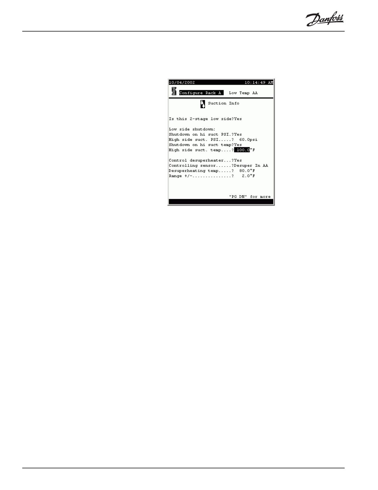
4-10 System Manual RC.IU.B3.22 AKC 55
for each suction group will include a special page for the low side. The screen looks
like this:
The fields and their contents are as follows:
Is this 2-stage low side (List box: Yes, No) Is this the low side of the two?
Low side shutdown:
Shutdown on hi suct PSI (List box: Yes, No) Whether or not to shut down the
low side compressors when high side reaches a
specified suction pressure.
High side suct. PSI (-99.0 to 200.0) The high side suction pressure at
which the low side will be shut down.
Control desuperheater (List box: Yes, No) Whether or not de-superheater
control is implemented on this rack.
Controlling sensor (List box:)
Desuper In AA: Control is based on a sensor moni-
toring the liquid in temperature at the de-superheater.
Desuper Out AA: Control is based on a sensor
monitoring the liquid out temperature at the de-super-
heater.
Suction Temp AA: Control is based on a sensor
monitoring suction temperature.
Desuperheating temp (-50.0 to 200.0)
Range +/- (1.0 TO 10.0)
Configuring
compressors To begin configuring compressors, select Compressors from the Configure Rack
menu. The first page of the screen looks like this:
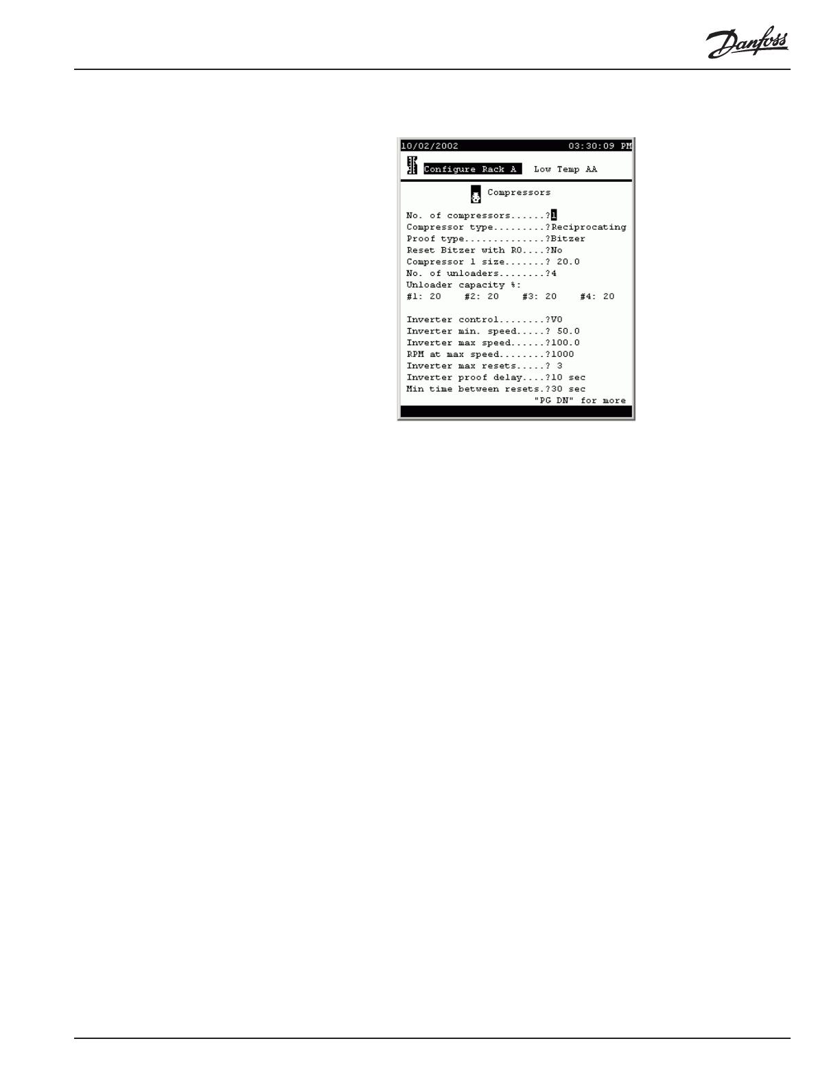
AKC 55 System Manual RC.IU.B3.22 4-11
The fields and their contents are as follows:
No. of compressors (0 to 9)
Proof type (List box:) The means by which proof of compressor
operation is monitored.
None: No proof
OI: A digital input (on-off input) is used for proof.
CT: A current transformer is used for proof.
Bitzer: Proof is obtained from a Bitzer electronic
module.
Reset Bitzer with RO (List box: Yes, No) Whether or not Bitzer compressors
are reset by a digital output (relay output).
Compressor size (1 to 500) The capacity of the compressor.
No. of unloaders (0 to 4) The number of compressor unloader stages.
Unloader capacity % (1 field per unloader: 0-99) The percent of capacity
shed by the respective unloader.
Inverter control (List box:) Type of variable speed control.
None: No inverter control
VO: An inverter is controlled by an analog output
(variable output).
VLT: A Danfoss VLT adjustable frequency drive is
used.
Inverter min. speed (1.0 to 150.0) The minimum percentage of rated speed
at which the inverter will run the compressor.
Inverter max speed (1.0 to 150.0) The maximum percentage of rated
speed at which the inverter will run the compressor.
RPM at max speed (1 to 9999) The RPM that will be displayed at maxi-
mum percentage.
Inverter max resets (0 to 10) The number of resets after which the
inverter will be put in override.
Inverter proof delay (0-99) The number of seconds without proof that must
elapse before an inverter reset occurs.
4-12 System Manual RC.IU.B3.22 AKC 55
Min time between resets (0 to 99) The number of seconds that must elapse
before second and subsequent inverter resets.
Configuring other
compressors in the
suction group Paging down, you will find a page for each compressor in the suction group. These
subsequent screens will have only questions pertaining to the individual compressors,
not the rack questions found at the top of the screen for compressor number one.
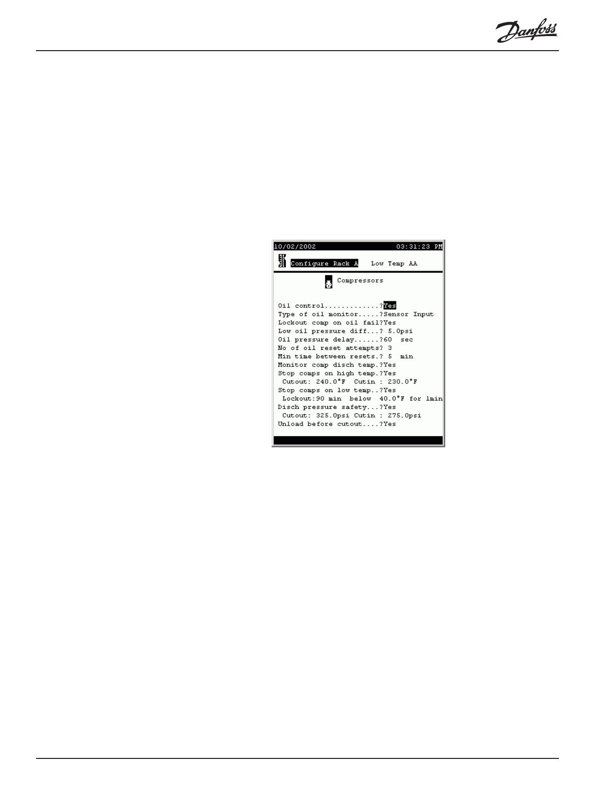
Compressor oil and
safety information After basic operating data has been entered for all compressors, paging down will
produce this screen:
The fields and their contents are as follows:
Oil control (List box: Yes, No) Whether or not oil control is
implemented.
Type of oil monitor (List box:)
Sensor Input: An analog input (sensor input) is used
to monitor oil pressure.
On/Off: A digital input (on-off input) is used to monitor
an oil pressure switch.
Copeland: A Copeland oil monitor is used.
Lockout comp on oil fail (List box: Yes, No) Whether or not compressors will
be locked out when an oil failure is detected.
Low oil pressure diff (0 to 50) The oil pressure differential, when an analog
sensor input is used, that will cause compressor
shutdown.
Oil pressure delay (0 to 255) When an analog sensor is used, the number
of seconds after oil failure is detected before compres-
sors are reset.
No of oil reset attempts (0 to 10) After oil failure is detected, the number of
reset attempts before compressors are locked out.
Min time between resets (0 to 60) After a reset (whether successful or not) the

AKC 55 System Manual RC.IU.B3.22 4-13
number of minutes that must elapse before another
reset attempt.
Monitor comp disch temp (List box: Yes, No) Whether or not compressor
discharge temperature is monitored.
Stop comps on high temp (List box: Yes, No) Whether or not compressors are to
be shut down on high discharge temperature.
Cutout (0.0 to 300.0) The discharge temperature at which
compressors are to be cut out.
Cutin (0.0 to 300.0) After a cut-out on high discharge
temperature, the discharge temperature at which
compressors are to be cut in.
Stop comps on low temp (List box: Yes, No) Whether or not comrpessors are to
be cut out on low discharge temperature.
Lockout (0 to 255) The number of minutes that must elapse
before a lockout on low discharge temperature. (See
note on next field).
below (0 to 300) The temperature that discharge must be
below for the time specified in the preceding field
before lockout on low discharge temperature occurs.
Note: If discharge temperature rises above the
setpoint, the time for lockout will restart from zero.
Disch pressure safety (List box: Yes, No) Whether or not comrpessors are to
be cut out on high discharge pressure.
Cutout (0.0 to 500.0) The discharge pressure at which com-
pressors are to be cut out.
Cutin (0.0 to 500.0) After a cut-out on high discharge
pressure, the discharge pressure at which compressors
are to be cut in.
Unload before cutout (List box: Yes, No) Whether or not comrpessors are to
be unloaded before being cut out.
Neutral Zone
control The next page of compressor configuration deals with neutral zone control. Basically,
neutral zone control acts to bring the current pressure toward target pressure more
quickly the greater the difference between the two. The screen looks like this:
4-14 System Manual RC.IU.B3.22 AKC 55
The default settings are as shown in the screen above. It is recommended that the
values not be changed without a thorough understanding of the algorithm. A thorough
explanation of neutral zone control is available as an appendix to this manual.
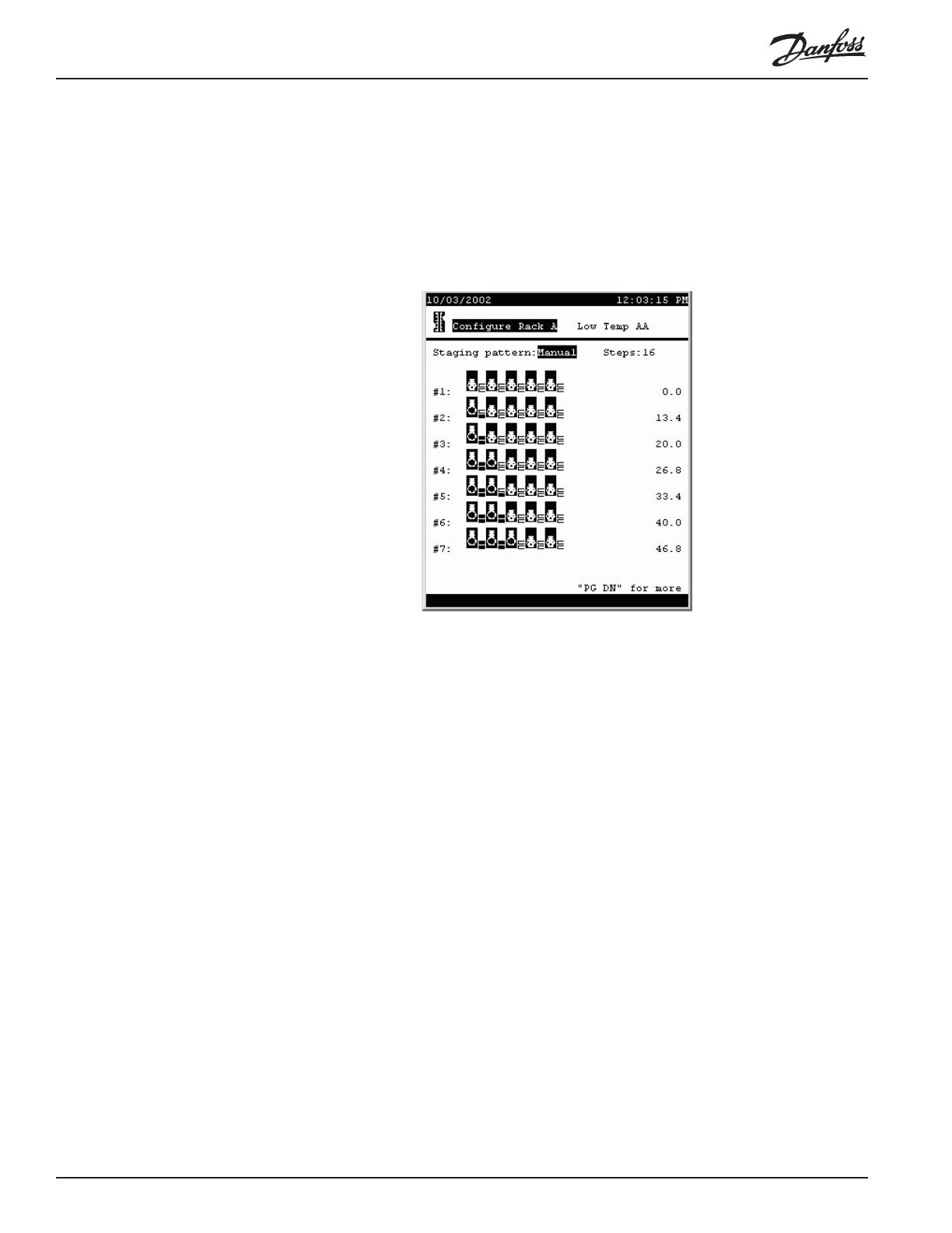
Compressor capacity
staging patterns Paging down from the neutral zone screen reveals the compressor staging pattern
screen:
In the default screen, the staging pattern is Auto, for automatic staging, and there is
no selection for Steps. The controller will stage capacity in the smallest steps avail-
able.
When there are a large number of steps, manual staging can be used to eliminate
needlessly small steps and compressor cycling.
To use manual staging, select Manual from the pattern list box, then specify the
number of steps you want. The display that results will show a row compressor icons
for each stage. A compressor’s unloaders are represented by the small rectangles to
the right of the compressor icon.
In the sample screen, compressors are all 20 HP and each has 2 unloaders. Each
unloader is 33% of compressor capacity. These settings were determined on the
configuration page for each compressor.
Stage #1 is fixed at zero capacity and cannot be changed.
To change stage #2 or any higher stage, move the cursor to a compressor icon and
press enter. You will notice that the “piston” in the icon moves. When it is up, the
compressor is on. If there are unloaders on a compressor, subsequent clicks on the
compressor icon will turn the unloader steps on, one at a time. The small rectangles
will change color to indicate that the step is on. When all steps are on for a compres-
sor, the next click on the icon will turn everything off.
AKC 55 System Manual RC.IU.B3.22 4-15
As you change a stage’s capacity, the number in the right column of the screen will
change for that stage, giving the total horsepower you have selected for that stage.
You can change the number of steps at any time.
Configuring
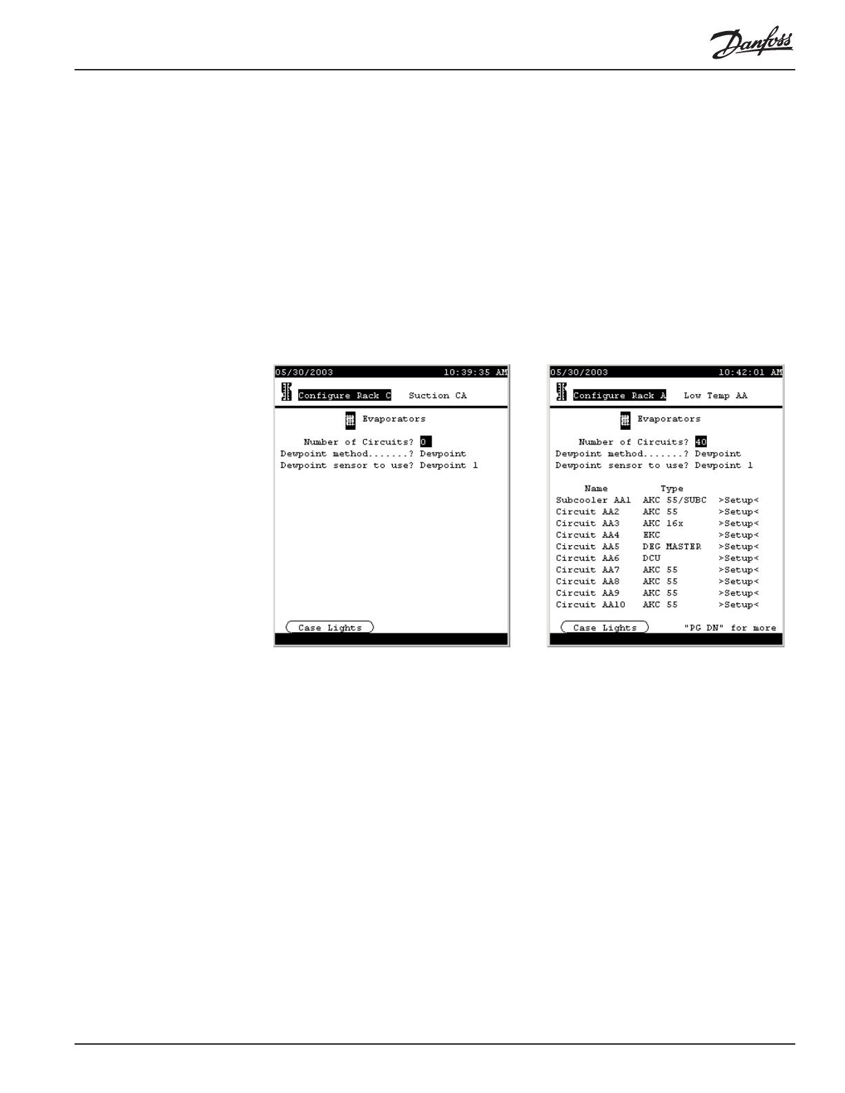
evaporators To begin configuration of evaporators, return to the Configure Rack menu and select
Evaporators. Or, from the Main Menu (which you can always reach with the
MENU key) select Configuration, Refrigeration, the particular rack, and Evaporators.
The evaporator menu will initially look like as on the left below, with no evaporators
listed, but as soon as you enter a number in answer to the top question, and select
from the Type list box for some of the evaporators, the screen will look something
like the one at right:
There are six kinds of evaporator control shown. In this manual, we will discuss the
configuration of AKC 55 circuits and AKC 16x circuits. For the other types of
evaporators, please see the manuals on the individual controllers. In the future, when
a Danfoss Case Control manual is created, we will remove the AKC 16x material
from this manual.
First, the changeable fields in the Evaporator Menu (shown above on the right) are as
follows:
Number of circuits (1 to 40) The number of circuits in the suction group.
Dewpoint method (List box:)
Dewpoint: A dewpoint sensor or sensors will be used
for anti-sweat control.
Calc Dewpoint: Dewpoint for anti-sweat control will
be calculated using the values of relative humidity and
temperature sensors.
Dewpoint sensor to use [If Dewpoint has been selected](List box:) How anti-

4-16 System Manual RC.IU.B3.22 AKC 55
sweat control dewpoint will be determined if a
dewpoint sensor is used.
Min Dewpoint: The lowest-reading of a number of
dewpoint sensors will be used.
Max Dewpoint: The highest-reading of a number of
dewpoint sensors will be used.
Average: The average of a number of dewpoint
sensors will be used.
Dewpoint 1: A single dewpoint sensor will be used for
control.
[others]: Other dewpoint sensors, if they exist, will be
listed also.
Humidity sensor to use: [If Calc Dewpoint has been selected](List box:) How
dewpoint will be determined if a humidity sensor is
used.
Min Humidity: The lowest-reading of a number of
humidity sensors will be used.
Max Humidity: The highest-reading of a number of
humidity sensors will be used.
Average: The average of a number of humidity
sensors will be used.
Inside RH 1: A single humidity sensor will be used
for control.
[others]: Other humidity sensors, if they exist, will be
listed also.
Type (List box:) [for each individual evaporator] the type of
evaporator control.
AKC 55/SUBC: A subcooler controlled as an AKC
55 circuit.
AKC 55: The circuit is controlled by the AKC 55’s
algorithms.
AKC 16x: Control is at the fixture by AKC 161 or
AKC 164 Smart Case Controllers.
EKC: Control is at the fixture by EKC 201 control-
lers.
Deg Master: Control is at the fixture by Hill/PHOE-
NIX Degree Master controllers.
DCU: Control is at the fixture by DCU case control-
lers.
Case lights button In the lower left corner of the screen body is a button, CASE LIGHTS. Selecting this
button and pressing ENTER will open the configuration screen for a case lights
override switch. The screen at left below appears (with the list box closed) when the
CASE LIGHTS button is activated. The fields on the screen and their meanings are
as follows:
Type of override switch (List box)
Disabled: There is no override switch configured.
On/Off: A two-position override switch allows the
lights to be switched on or off.
On/Auto:

AKC 55 System Manual RC.IU.B3.22 4-17
Off/Auto: Choices are OFF or automatic operation.
On/Auto/Off: All three choices are available with a
three position switch being installed.
Dewpoint for anti-sweat control will be calculated
using the values of relative humidity and temperature
sensors.
Configuring AKC 55
subcooling circuits When subcooler valves are controlled directly by the AKC 55 (that is, when an AKC
165 Subcooling Controller is not used) configuration begins by selecting AKC 55/
SUBC in the Type column for the circuit on the Evaporator Menu, then moving the
cursor to the word Setup for that evaporator and pressing ENTER. A screen like the
one at left below will appear. The same screen with all its fields revealed appears as
at right.
4-18 System Manual RC.IU.B3.22 AKC 55
The fields are as follows:
Number of valves (0 to 2) The number of valves used for subcooling.
Number of stages (1 to 3) With one valve, there can be only 1 stage of
subcooling. With two valves, there can be two stages
(one valve open or two). If there are two valves
feeding subcoolers of different capacities, then there
can be three stages (only valve 1 open, only valve 2
open, or both valves open).
Cutin setpoint (0.0 to 120.0, each stage has a separate setpoint) The
temperature at which the subcooling stage will become
active. Temperature is measured by a sensor at the
liquid outlet of the subcooler.
Cutout setpoint: (0.0 to 110.0, each stage has a separate setpoint) The
temperature at which the subcooling stage will shut
down.
Minimum ON time (0 to 255) The minimum time in minutes each stage
must remain active after being cut in.
Minimum OFF time (0 to 255) The minimum time in minutes each stage
must remain off after being cut out.
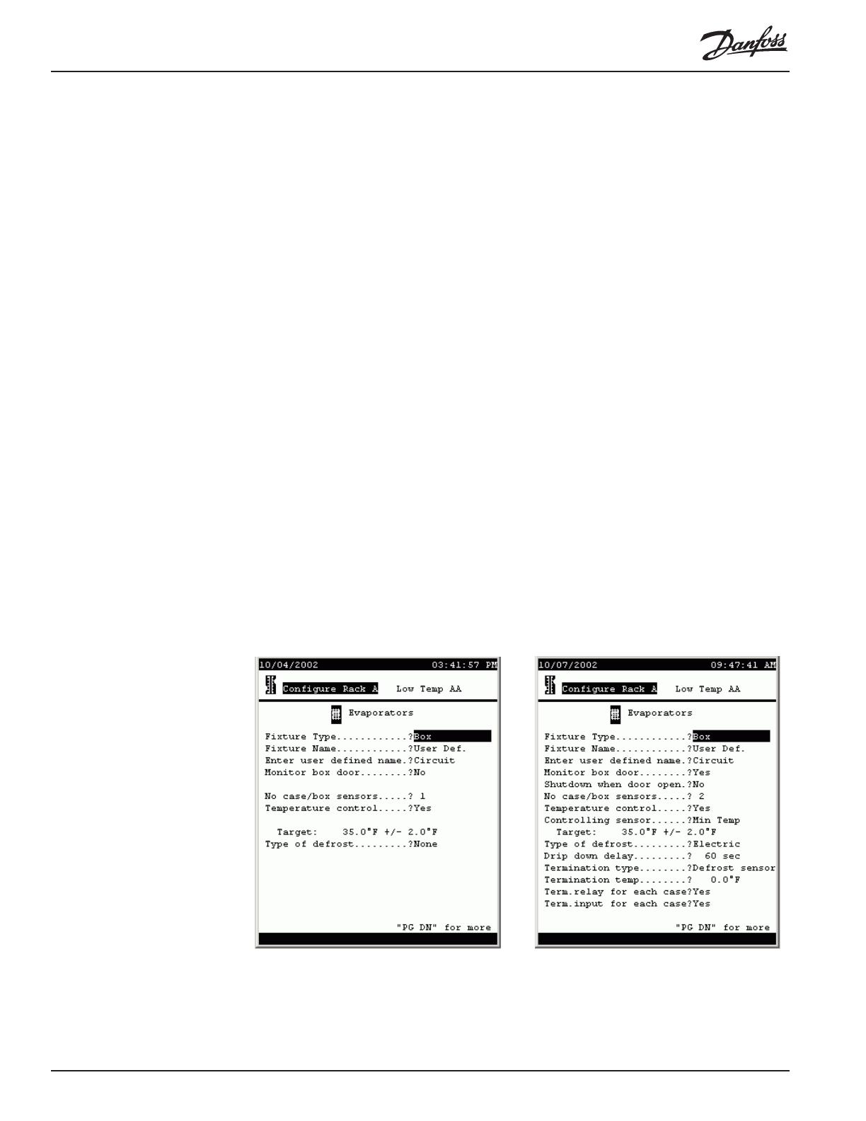
Configuring AKC 55
refrigeration circuits If there is not a distributed controller at the fixture (AKC 161, AKC 164, Degree
Master, or DCU), refrigeration can be controlled directly by the AKC 55. Configura-
tion of such circuits starts by selecting AKC 55 in the Type column for the circuit on
the Evaporator menu, then moving the cursor to the word Setup for that evaporator
and pressing ENTER. A screen like the one at left below will appear. The same
screen with all its fields revealed appears as at right.
The fields are as follows:
Fixture Type (List box) Various types of fixture can be selected:

AKC 55 System Manual RC.IU.B3.22 4-19
box, multi-deck, single deck, service, etc.
Fixture Name (List box) There is a large selection of common fixture
names for each of the fixture types that can be se-
lected above, and there is a selection User Def. After
making that selection, you will be able to spell out your
own name on the following line.
Enter user defined name (Label) The name of a user-defined fixture. Any of
the characters in the AKC 55 character set can be
used, including upper and lower case letters and
symbols.
Monitor box door (List box: Yes, No) Whether or not a box door switch
will be monitored (appears for boxes only).
Shutdown when door open (List box: Yes, No) Whether or not to shut down
refrigeration when the box door is open.
No case/box sensors (0 to 15) The number of sensors in this fixture or
circuit.
Temperature control (List box: Yes, No) Whether or not temperature contol
will be used.
Controlling sensor (List box:)
Min Temp The lowest of the sensors in the fixture or
on the circuit will be used for temperature control.
Max Temp The highest of the sensors in the fixture
or on the circuit will be used for temperature control.
Average The average of all the sensors in the fixture
or on the circuit will be used for temperature control.
[circuit names] The name of each sensor will be
listed, and any can be selected. That sensor, then, will
be used for temperature control.
Target: (-99.0 to 150.0 [target] 1.0 to 20.0 [range] The target
temperature and the range about the target, used in
temperature control. The range is the amount above or
below target that the actual sensor temperature is
allowed to change before a control action is taken.
Type of defrost (List box) Various types of defrost can be chosen:
None, Hot Gas, Time Off, Air, or Electric.
Drip down delay (1 to 600) The number of seconds that refrigeration
will remain off after termination of defrost.
Termination type [Defrost time settings made on the pages that follow
must also be considered. If a minimum defrost time
is used, that time must elapse regardless of the
settings made on this page. If a defrost duration is
specified, either that time must elapse OR the
requirements set on this page must be satisfied for
defrost to terminate.]
(List box) Various termination strategies are listed.
Defrost sensor There is a dedicated defrost tem-
perature sensor that will be used to terminate defrost.
Disch air snsr The fixture discharge air sensor will
be used to terminate defrost at a set temperature.
On/Off Input An electrical switch (such as a Klixon
®

4-20 System Manual RC.IU.B3.22 AKC 55
is wired to a digital input (on-off input) and will be used
to terminate defrost.
None: Defrost is terminated strictly on time.
Hot gas return: Hot gas defrost is terminated when a
return air sensor reaches a setpoint.
Termination temp (-99.0 to 200.0) The defrost temperature sensor value
at which defrost will terminate.
Term.relay for each case (List box: Yes, No) Whether or not there is a termina-
tion relay for each case.
Term.relay for each case (List box: Yes, No) Whether or not there is a termina-
tion input each case.
Paging down produces the next page:
[Defrost time settings made on this and the following pages work with the
termination settings on the preceding page. If a minimum defrost time is used,
that time must elapse AND the settings for defrost termination temperature or
switch must be satisfied. If a defrost duration is specified, either that time must
elapse OR the requirements set on this page must be satisfied for defrost to
terminate.]
The fields are as follows:
Use min defrost time (List box: Yes, No) Whether or not minimum defrost
time will be used.
Minimum defrost time (1 to 180) The number of minutes defrost must be on
before termination.
Antisweat control (List box: Yes, No) Whether or not anti-sweat heaters
will be controlled by the AKC 55. When you configure
an evaporator and answer Yes to the anti-sweat control
question, a relay output is created which is then wired
to a relay controlling the anti-sweat heaters. The name
/